Page 1436 of 4087
(b) Remove any oil or water on the crankshaft pulley, oil pumppulley, water pump pulley, No.1 idler pulley and No.2 idler
pulley, and keep them clean.
(c) Align the installation mark on the timing belt with the dot mark
of the crankshaft timing pulley.
(d) Install the timing belt on the crankshaft timing pulley. No.1 idler pulley and No.2 idler pulley.
5. INSTALL TIMING BELT GUIDE (CRANKSHAFT ANGLE SENSOR PLATE)
Install the belt guide, facing the cup side outward.
6. INSTALL TIMING BELT COVER SPACER
(a) Install the gasket to the cover spacer.
(b) Install the cover spacer.
7. INSTALL NO.1 TIMING BELT COVER
(a) Install the gasket to the timing belt cover.
(b) Install the timing belt cover with the 4 bolts.
EG±60
±
1UZ±FE ENGINE ENGINE MECHANICAL
WhereEverybodyKnowsYourName
Page 1437 of 4087

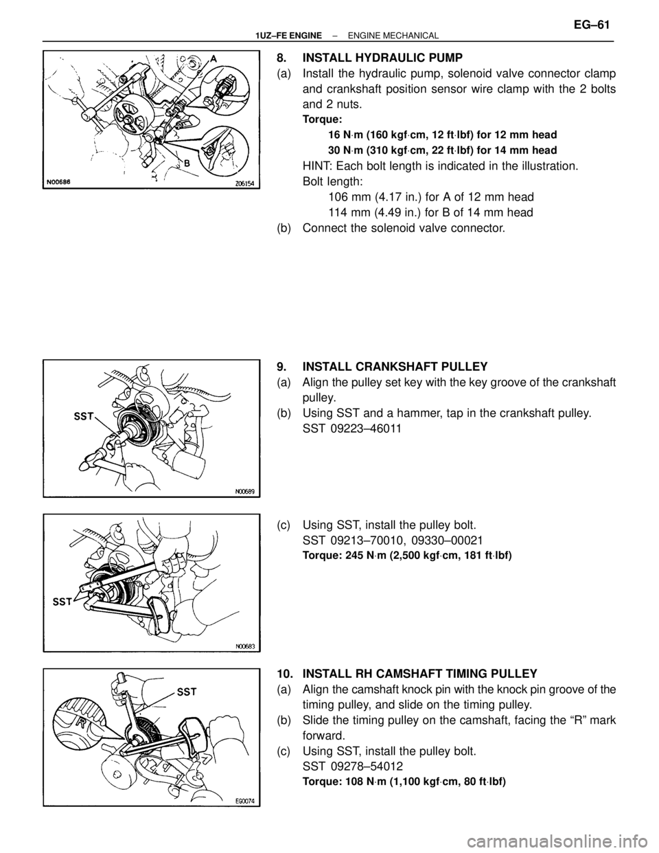
8. INSTALL HYDRAULIC PUMP
(a) Install the hydraulic pump, solenoid valve connector clampand crankshaft position sensor wire clamp with the 2 bolts
and 2 nuts.
Torque:
16 NVm (160 kgf Vcm, 12 ft Vlbf) for 12 mm head
30 N Vm (310 kgf Vcm, 22 ft Vlbf) for 14 mm head
HINT: Each bolt length is indicated in the illustration.
Bolt length:
106 mm (4.17 in.) for A of 12 mm head
114 mm (4.49 in.) for B of 14 mm head
(b) Connect the solenoid valve connector.
9. INSTALL CRANKSHAFT PULLEY
(a) Align the pulley set key with the key groove of the crankshaft pulley.
(b) Using SST and a hammer, tap in the crankshaft pulley. SST 09223±46011
(c) Using SST, install the pulley bolt. SST 09213±70010, 09330±00021
Torque: 245 N Vm (2,500 kgf Vcm, 181 ft Vlbf)
10. INSTALL RH CAMSHAFT TIMING PULLEY
(a) Align the camshaft knock pin with the knock pin groove of the
timing pulley, and slide on the timing pulley.
(b) Slide the timing pulley on the camshaft, facing the ªRº mark forward.
(c) Using SST, install the pulley bolt. SST 09278±54012
Torque: 108 N Vm (1,100 kgf Vcm, 80 ft Vlbf)
±
1UZ±FE ENGINE ENGINE MECHANICALEG±61
WhereEverybodyKnowsYourName
Page 1442 of 4087

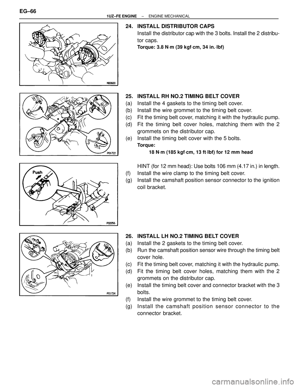
24. INSTALL DISTRIBUTOR CAPSInstall the distributor cap with the 3 bolts. Install the 2 distribu-
tor caps.
Torque: 3.8 N Vm (39 kgf Vcm, 34 in. Vlbf)
25. INSTALL RH NO.2 TIMING BELT COVER
(a) Install the 4 gaskets to the timing belt cover.
(b) Install the wire grommet to the timing belt cover.
(c) Fit the timing belt cover, matching it with the hydraulic pump.
(d) Fit the timing belt cover holes, matching them with the 2
grommets on the distributor cap.
(e) Install the timing belt cover with the 5 bolts.
Torque:
18 NVm (185 kgf Vcm, 13 ft Vlbf) for 12 mm head
HINT (for 12 mm head): Use bolts 106 mm (4.17 in.) in length.
(f) Install the wire clamp to the timing belt cover.
(g) Install the camshaft position sensor connector to the ignition coil bracket.
26. INSTALL LH NO.2 TIMING BELT COVER
(a) Install the 2 gaskets to the timing belt cover.
(b) Run the camshaft position sensor wire through the timing belt
cover hole.
(c) Fit the timing belt cover, matching it with the hydraulic pump.
(d) Fit the timing belt cover holes, matching them with the 2 grommets on the distributor cap.
(e) Install the timing belt cover and connector bracket with the 3 bolts.
(f) Install the wire grommet to the timing belt cover.
(g) In sta ll th e ca msh a ft po sitio n se n so r c onnector to the
connector bracket.
EG±66
±
1UZ±FE ENGINE ENGINE MECHANICAL
WhereEverybodyKnowsYourName
Page 1447 of 4087
(e) Connect the following hoses:(1) 2 oil cooler hoses (for cooling fan) to pipes
(2) 2 radiator hoses
(3) 2 oil cooler hoses (for transmission) to radiator
(4) Suction hose to hydraulic pump
(5) Pressure hose to hydraulic pump
(f) Connect the ECT sensor connector (for cooling fan).
(g) Install the ECT sensor wire clamp to the radiator fan shroud.
±
1UZ±FE ENGINE ENGINE MECHANICALEG±71
WhereEverybodyKnowsYourName
Page 1448 of 4087
39. INSTALL RADIATOR RESERVOIR TANK
(a) Install the reservoir tank to the reservoir tank bracket.
(b) Install the reservoir tank with the bracket and 3 bolts.
Torque: 4.9 NVm (50 kgf Vcm, 43 in. Vlbf)
(c) Connect the following hoses:
(1) Reservoir hose to water inlet housing
(2) Reservoir hose to radiator
(d) Connect the coolant level sensor connector.
40. INSTALL DRIVE BELT Install the drive belt by turning the drive belt tensioner coun-
terclockwise.
HINT: The pulley bolt for the dive belt tensioner has a left
hand thread.
41. INSTALL BATTERY
42. FILL WITH ENGINE COOLANT
43. START ENGINE AND CHECK FOR LEAKS
44. CHECK TRANSMISSION FLUID LEVEL
45. INSTALL ENGINE UNDER COVER
EG±72
±
1UZ±FE ENGINE ENGINE MECHANICAL
WhereEverybodyKnowsYourName
Page 1455 of 4087
(c) Remove the bolt, 2 nuts, the EGR valve, vacuum modulatorassembly and gasket.
14. REMOVE EGR VALVE ADAPTOR
(a) Disconnect the EGR gas temperature sensor connector.
(b) Disconnect the PCV hose from the cylinder head.
(c) Remove the 2 bolts, 2 nuts, EGR adaptor and gasket.
15. REMOVE IAC VALVE
(a) Disconnect the IAC valve connector.
(b) Disconnect the water bypass hose from the IAC valve.
(c) Remove the 2 nuts, IAC valve and gasket.
±
1UZ±FE ENGINE ENGINE MECHANICALEG±79
WhereEverybodyKnowsYourName
Page 1456 of 4087
16. REMOVE HEATER WATER VALVE FROM BODY
(a) Disconnect the VSV connector.
(b) Disconnect the bolt holding the engine wire clamp to thewater valve bracket.
(c) Remove the 2 bolts, and disconnect the water valve and bracket assembly.
17. REMOVE THROTTLE BODY
(a) Disconnect the following connectors: (1) Throttle position sensor connector
(2) w/ TRAC:
Sub±throttle position sensor connector
(3) w/ TRAC: Sub±throttle actuator connector
(b) Remove the 2 bolts and 2 nuts, and disconnect the throttle body from the air intake chamber.
(c) Disconnect the following hoses, and remove the throttle body:
(1) PCV hose from throttle body
(2) Water bypass hose from throttle body
(d) Remove the throttle body gasket.
18. REMOVE AIR INTAKE CHAMBER
(a) Disconnect the following hoses: (1) Brake booster vacuum hose from union on air intake
chamber
(2) Vacuum hose (from VSV for heater water valve) from air
intake chamber
EG±80
±
1UZ±FE ENGINE ENGINE MECHANICAL
WhereEverybodyKnowsYourName
Page 1460 of 4087
(d) Pull out the 8 injectors from the delivery pipes.
(e) Remove the O±ring and grommet from each injector.
27. REMOVE INTAKE MANIFOLDRemove the 6 bolts, 4 nuts, intake manifold and 2 gaskets.
28. REMOVE FRONT WATER BYPASS JOINT
(a) Disconnect the following connectors: (1) ECT sensor connector
(2) Cold start injector time switch connector
(3) ECT sender gauge connector
(b) Remove the bolt, and disconnect the engine wire protector from the water bypass joint.
(c) Remove the 4 nuts, water bypass joint and 2 gaskets.
29. REMOVE REAR WATER BYPASS JOINT
(a) Remove the bolt holding the water bypass pipe to the LH rear
engine hanger.
(b) Remove the 4 nuts, water bypass joint and 2 gasket.
EG±84
±
1UZ±FE ENGINE ENGINE MECHANICAL
WhereEverybodyKnowsYourName