Page 1422 of 4087

EG21P±02
TIMING BELT REMOVAL
(See Components for Removal and Installation)
1. REMOVE BATTERY CAUTION: Work must be started after 90 seconds from
the time the ignition switch is turned to the ªLOCKº posi-
tion and the negative (±) terminal cable is disconnected
from the battery.
2. REMOVE ENGINE UNDER COVER
3. DRAIN ENGINE COOLANT
4. REMOVE DRIVE BELT
Loosen the drive belt tension by turning the drive belt tension-
er counterclockwise, and remove the drive belt.
HINT: The pulley bolt for the drive belt tensioner has a left±
hand thread.
5. REMOVE RADIATOR RESERVOIR TANK
(a) Disconnect the coolant level sensor connector.
(b) Disconnect the following hoses: (1) Reservoir hose from water inlet housing
(2) Reservoir hose from radiator
(c) Remove the 2 bolts and reservoir tank bracket.
(d) Remove the bolt holding the reservoir tank to the radiator.
(e) Disconnect the reservoir tank from the reservoir tank bracket,
and remove the reservoir tank.
6. REMOVE RADIATOR ASSEMBLY
(a) Disconnect the ECT sensor connector (for cooling fan).
(b) Disconnect the ECT sensor wire clamp from the radiator fan shroud.
EG±46
±
1UZ±FE ENGINE ENGINE MECHANICAL
WhereEverybodyKnowsYourName
Page 1448 of 4087
39. INSTALL RADIATOR RESERVOIR TANK
(a) Install the reservoir tank to the reservoir tank bracket.
(b) Install the reservoir tank with the bracket and 3 bolts.
Torque: 4.9 NVm (50 kgf Vcm, 43 in. Vlbf)
(c) Connect the following hoses:
(1) Reservoir hose to water inlet housing
(2) Reservoir hose to radiator
(d) Connect the coolant level sensor connector.
40. INSTALL DRIVE BELT Install the drive belt by turning the drive belt tensioner coun-
terclockwise.
HINT: The pulley bolt for the dive belt tensioner has a left
hand thread.
41. INSTALL BATTERY
42. FILL WITH ENGINE COOLANT
43. START ENGINE AND CHECK FOR LEAKS
44. CHECK TRANSMISSION FLUID LEVEL
45. INSTALL ENGINE UNDER COVER
EG±72
±
1UZ±FE ENGINE ENGINE MECHANICAL
WhereEverybodyKnowsYourName
Page 1517 of 4087
12. REMOVE RADIATOR RESERVOIR TANK
(a) Disconnect the coolant level sensor connector.
(b) Disconnect the following hoses:(1) Reservoir hose from water inlet housing
(2) Reservoir hose from radiator
(c) Remove the 2 bolts and reservoir tank bracket.
(d) Remove the bolt holding the reservoir tank to the radiator.
(e) Disconnect the reservoir tank from the reservoir tank bracket,
and remove the reservoir tank.
13. REMOVE RADIATOR ASSEMBLY
(a) Disconnect the ECT sensor connector (for cooling fan).
(b) Disconnect the ECT sensor wire clamp from the radiator fan shroud.
(c) Disconnect the following hoses: (1) 2 oil cooler hoses (for cooling fan) from pipes
(2) 2 radiator hoses
±
1UZ±FE ENGINE ENGINE MECHANICALEG±141
WhereEverybodyKnowsYourName
Page 1577 of 4087
(f) Connect the ECT sensor connector (for cooling fan).
(g) Install the ECT sensor wire clamp to the radiator fan shroud.
26. INSTALL RADIATOR RESERVOIR TANK
(a) Install the reservoir tank to the reservoir tank bracket.
(b) Install the reservoir tank with the bracket and 3 bolts.
Torque: 4.9 N.m (50 kgfVcm, 43 in. Vlbf)
(c) Connect the following hoses:
(1) Reservoir hose to water inlet housing
(2) Reservoir hose to radiator
(d) Connect the coolant level sensor connector.
27. INSTALL INTAKE AIR CONNECTOR
(a) Connect the intake air connector to the throttle body.
(b) Install the hose clamp and bolt.
(c) Connect the following hoses to the intake air connector: (1) Air hose (from IAC valve)
(2) Air hose (from air control valve on PS pump)
28. CONNECT VACUUM HOSE (A) (FROM PS AIR CONTROL VALVE) TO AIR INTAKE CHAMBER
±
1UZ±FE ENGINE ENGINE MECHANICALEG±201
WhereEverybodyKnowsYourName
Page 1585 of 4087
12. REMOVE RADIATOR RESERVOIR TANK(a) Disconnect the coolant level sensor connector.
(b) Disconnect the following hoses:(1) Reservoir hose to water inlet housing
(2) Reservoir hose to radiator
(c) Remove the two bolts and reservoir tank bracket.
(d) Disconnect the reservoir tank from the reservoir tank bracket, and remove the reservoir tank.
13. REMOVE RADIATOR (a) Disconnect the water temperature sensor connector.
(b) Disc onnect the wire clamp (for water temperature
sensor) from the radiator fan shrould.
(c) Disconnect the following hoses: (1) Two oil cooler hoses (for cooling fan) from pipes
(2) Two radiator hoses
EM±120
±
ENGINE MECHANICAL Cylinder Block
WhereEverybodyKnowsYourName
Page 1641 of 4087

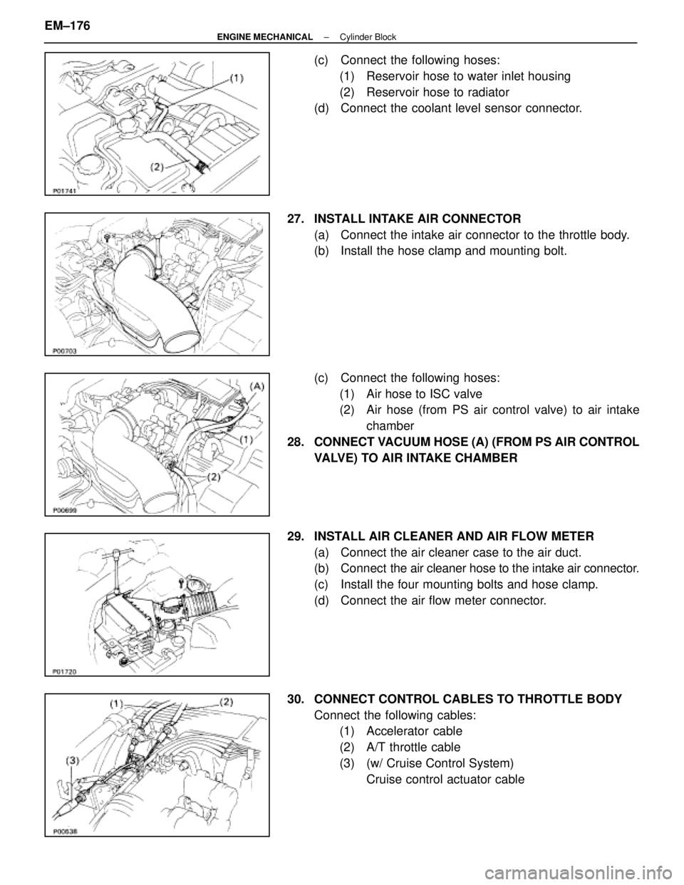
(c) Connect the following hoses:(1) Reservoir hose to water inlet housing
(2) Reservoir hose to radiator
(d) Connect the coolant level sensor connector.
27. INSTALL INTAKE AIR CONNECTOR (a) Connect the intake air connector to the throttle body.
(b) Install the hose clamp and mounting bolt.
(c) Connect the following hoses:(1) Air hose to ISC valve
(2) Air hose (from PS air control valve) to air intake chamber
28. CONNECT VACUUM HOSE (A) (FROM PS AIR CONTROL VALVE) TO AIR INTAKE CHAMBER
29. INSTALL AIR CLEANER AND AIR FLOW METER (a) Connect the air cleaner case to the air duct.
(b) Connect the air cleaner hose to the intake air connector.
(c) Install the four mounting bolts and hose clamp.
(d) Connect the air flow meter connector.
30. CONNECT CONTROL CABLES TO THROTTLE BODY Connect the following cables:(1) Accelerator cable
(2) A/T throttle cable
(3) (w/ Cruise Control System)
Cruise control actuator cable
EM±176
±
ENGINE MECHANICAL Cylinder Block
WhereEverybodyKnowsYourName
Page 1642 of 4087

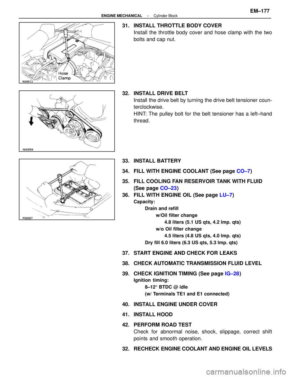
31. INSTALL THROTTLE BODY COVERInstall the throttle body cover and hose clamp with the two
bolts and cap nut.
32. INSTALL DRIVE BELT Install the drive belt by turning the drive belt tensioner coun-
terclockwise.
HINT: The pulley bolt for the belt tensioner has a left±hand
thread.
33. INSTALL BATTERY
34. FILL WITH ENGINE COOLANT (See page CO±7)
35. FILL COOLING FAN RESERVOIR TANK WITH FLUID (See page CO±23)
36. FILL WITH ENGINE OIL (See page LU±7)
Capacity:
Drain and refill
w/Oil filter change4.8 liters (5.1 US qts, 4.2 lmp. qts)
w/o Oil filter change 4.5 liters (4.8 US qts, 4.0 lmp. qts)
Dry fill 6.0 liters (6.3 US qts, 5.3 lmp. qts)
37. START ENGINE AND CHECK FOR LEAKS
38. CHECK AUTOMATIC TRANSMISSION FLUID LEVEL
39. CHECK IGNITION TIMING (See page IG±28)
Ignition timing:
8±125 BTDC @ idle
(w/ Terminals TE1 and E1 connected)
40. INSTALL ENGINE UNDER COVER
41. INSTALL HOOD
42. PERFORM ROAD TEST Check for abnormal noise, shock, slippage, correct shift
points and smooth operation.
32. RECHECK ENGINE COOLANT AND ENGINE OIL LEVELS
±
ENGINE MECHANICAL Cylinder BlockEM±177
WhereEverybodyKnowsYourName
Page 1647 of 4087

The 1 UZ±FE engine has 8±cylinders in a V±arrangement at a bank an\
gle of 905. From the front of the RH
bank cylinders are numbered 2±4±6±8, and from the front of the LH b\
ank cylinders are numbered 1 ±3±5±7.
The crankshaft is supported by 5 bearings specified by the inside of the cr\
ankcase. These bearings are made
of a copper and lead alloy. The crankshaft is integrated with 8 weights which are cast along with it\
for balancing. Oil holes are built
into the center of the crankshaft for supplying oil to the connecting ro\
ds, pistons and other components. The ignition order is 1±8±4±3±6±5±7±2. The cylinder\
head is made of aluminum alloy, with a cross flow
type intake and exhaust layout and with pent±roof type combustion chambers. The spark plugs are loca\
ted in
the center of the combustion chambers.
At the front and rear of the intake manifold, a water passage has been p\
rovided which connects the RH
and LH cylinder heads. Exhaust and intake valves are equipped with irregular pitch springs made\
of special valve spring carbon
steel which are capable of following no matter what the engine speed.
The RH and LH intake camshafts are driven by a single timing belt, and a ge\
ar on the intake camshaft en-
gages with a gear on the exhaust camshaft to drive it. The camshaft jour\
nal is supported at 5 (intake) or 4 (ex-
haust) places between the valve lifters of each cylinder and on the front end of the cylinder \
head. Lubrication
of the cam journal gear is accomplished by oil being supplied through the \
oiler port in the center of the camshaft. Adjustment of the valve clearance is done by means of an outer shim type\
system, in which valve adjusting
shims are located above the valve lifters. This permits replacement of the sh\
ims without removal of the cam-
shafts. Pistons are made of high temperature±resistant aluminum alloy, and a depression is built into the piston
head to prevent interference with valves.
Piston pins are the full±floating type, with the pins fastened to neither the piston boss nor the connecting
rods. Instead, snap rings are fitted on both ends of the pins, preventing the\
pins from falling out. The No.1 compression ring is made of steel and the No.2 compression ring\
is made of cast iron. The oil
ring is m ade of a combination of steel and stainless steel. The outer diameter of\
each piston ring is slightly larger
than the diameter of the piston and the flexibility of the rings allows them\
to hug the cylinder walls when they
are mounted on the piston. Compression rings No.1 and No.2 work to prevent \
the leakage of gas from the cylin-
der and the oil ring works to scrape oil off the cylinder walls to prevent it from entering the combustion chamber. The cylinder block is made of aluminum alloy with a bank angle of 90 5. Cast iron cylinders are installed
inside the cylinder block. It has 8 cylinders which are approximately twice the length of th\
e piston stroke. The
top of each cylinder is closed off by the cylinder heads and the lower end of the cylinders becomes the crank-
case, in which the crankshaft is installed. In addition, the cylinder bl\
ock contains a water jacket, through which
coolant is pumped to cool the cylinders. The No.1 and No.2 oil pans are bolted onto the bottom of the cylinder block\
. The No.1 oil pan is made of
aluminum alloy. The No.2 oil pan is an oil reservoir made of pressed steel sheet. An o\
il level sensor is installed
in the No.1 oil pan (If the oil level drops below a set level, a warnin\
g light lights up.). A oil pan baffle plate keeps
sufficient oil in the bottom of the No.2 oil pan even when the vehicle is tilted. \
This dividing plate also prevents
the oil from making waves when the vehicle is stopped suddenly and the oil \
shifts away from the oil pump suction
pipe. Plastic region tightening bolts are used for the cylinder head, main bearing ca\
p and connecting rod.
EM±4
±
ENGINE MECHANICAL Operation
WhereEverybodyKnowsYourName