Page 661 of 4087
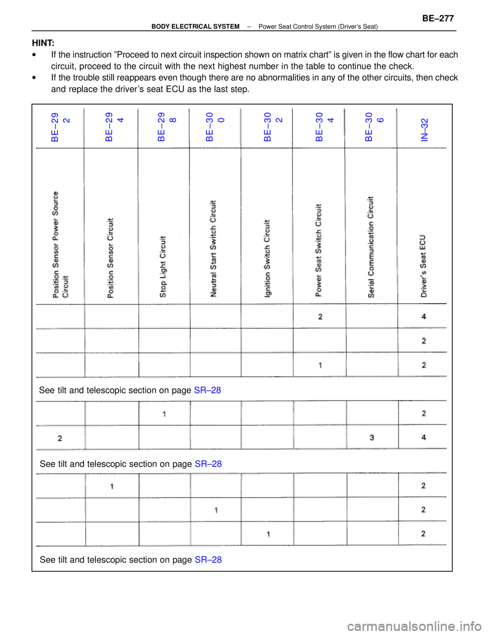
BE±292
BE±29 4
BE±29 8
BE±30 0
BE±30 2
BE±30 4
BE±30 6
IN±32
See tilt and telescopic section on page SR±28
See tilt and telescopic section on page SR±28
See tilt and telescopic section on page SR±28
HINT:
w
If the instruction ºProceed to next circuit inspection shown on matrix \
chartº is given in the flow chart for each
circuit, proceed to the circuit with the next highest number in the table to con\
tinue the check.
w If the trouble still reappears even though there are no abnormalities in a\
ny of the other circuits, then check
and replace the driver's seat ECU as the last step.
±
BODY ELECTRICAL SYSTEM Power Seat Control System (Driver's Seat)BE±277
WhereEverybodyKnowsYourName
Page 746 of 4087
OKNG
NGOK
*1: The power source is supplied to the actuator (doorlock motor, luggage compartment door opener mo-
tor) through the theft deterrent and door lock ECU.
Accordingly, if a short circuit of the W/H or actuator
occurs in the actuator circuit, the DOOR fusible link
may become OPEN, so also inspect the actuator
(door lock motor circuit on page BE±380, and the
luggage compartment door opener motor circuit on
page BE±382 ).
INSPECTION PROCEDURE
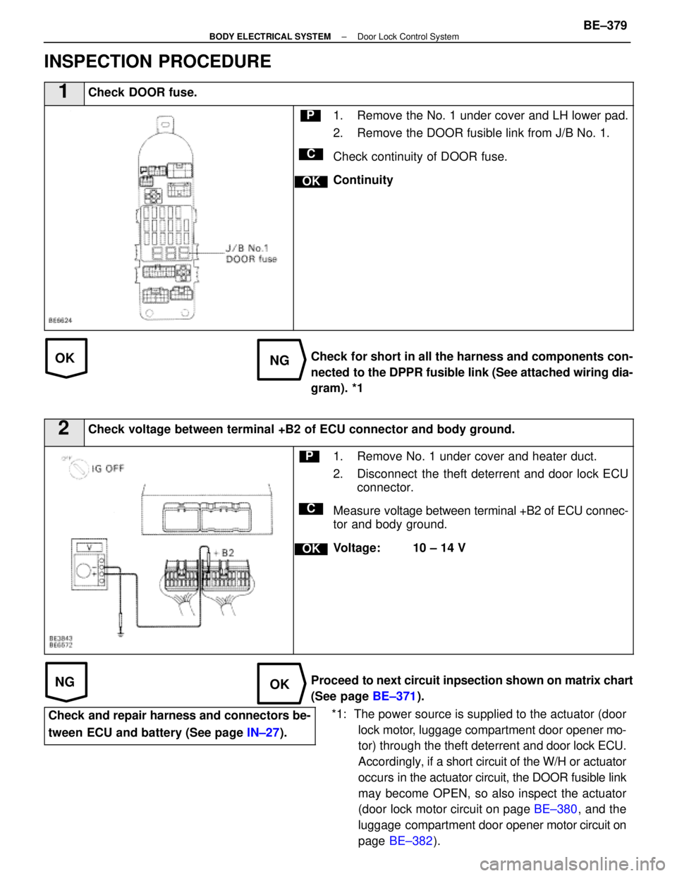
1Check DOOR fuse.
C
OK
P1. Remove the No. 1 under cover and LH lower pad.
2. Remove the DOOR fusible link from J/B No. 1.
Check continuity of DOOR fuse.
Continuity
Check for short in all the harness and components con-
nected to the DPPR fusible link (See attached wiring dia-
gram). *1
2Check voltage between terminal +B2 of ECU connector and body ground.
C
OK
P1. Remove No. 1 under cover and heater duct.
2. Disconnect the theft deterrent and door lock ECU connector.
Measure voltage between terminal +B2 of ECU connec-
tor and body ground.
Voltage: 10 ± 14 V
Proceed to next circuit inpsection shown on matrix chart
(See page BE±371).
Check and repair harness and connectors be-
tween ECU and battery (See page IN±27).
±
BODY ELECTRICAL SYSTEM Door Lock Control SystemBE±379
WhereEverybodyKnowsYourName
Page 750 of 4087
OKNG
OKNG
INSPECTION PROCEDURE
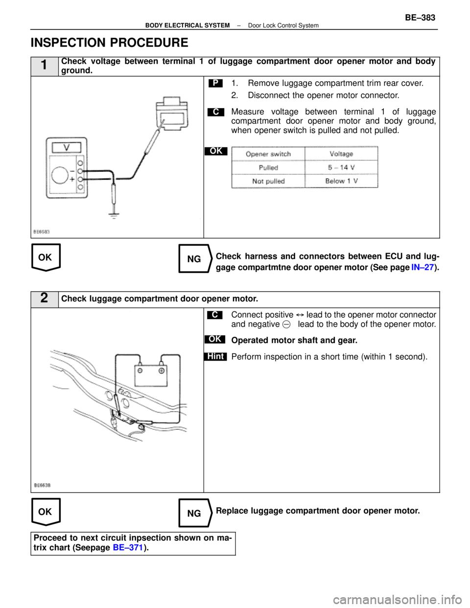
1Check voltage between terminal 1 of luggage compartment door opener motor and body
ground.
C
OK
P1. Remove luggage compartment trim rear cover.
2. Disconnect the opener motor connector.
Measure voltage between terminal 1 of luggage
compartment door opener motor and body ground,
when opener switch is pulled and not pulled.
Check harness and connectors between ECU and lug-
gage compartmtne door opener motor (See page IN±27).
2Check luggage compartment door opener motor.
C
OK
Hint
Connect positive � lead to the opener motor connector
and negative �lead to the body of the opener motor.
Operated motor shaft and gear.
Perform inspection in a short time (within 1 second).
Replace luggage compartment door opener motor.
Proceed to next circuit inpsection shown on ma-
trix chart (Seepage BE±371).
±
BODY ELECTRICAL SYSTEM Door Lock Control SystemBE±383
WhereEverybodyKnowsYourName
Page 769 of 4087

PRECHECK TYPE I
In cases where the wireless door lock control system fails to operate only\
at a specific locality, perform this check
at that locality.
Open the driver's door
(Other doors remain closed).Using the door lock control switch, perform
ªlock, unlockº
*1 operation 10 times within 30
seconds.
How many times in 10 seconds is ªlock, un-
lockº
*1 operation performed automatically by
the ECU?
Noise is being produced at that locality.
*3
Vehicle is now receiving signals from a
transmitter of another vehicle (during
transmission from transmitter of another
vehicle).
Malfunction on vehicle side
(Proceed to Matrix Chart of Problem
Symptom on page
BE±454).
Does not
operate
2 times
3 times
Normal
*2
*1: Performing lock and unlock once counts as one time.
*2: If noise is not constantly produced at the locality being used and inspect\
ion is performed on an occasion when there is no noise, then it may happen that the system is judged normal.\
*3: If the conclusion is that noise is produced in the locality the vehicle is\
used, then transmitter use is limited in that locality. Limitations on usage are described below.
HINT:
Because the transmitter uses weak electromagnetic waves, it is easily affected by noise, so remote control with-
in the normal range becomes difficult.
To reduce the influence of noise, bring the transmitter as close as possib\
le to the back window glass (antenna
section), or touch (ground) the grooved key tip of the transmitter to\
the door key cylinder and then operate the
transmitter switch; this should make door lock remote control operation possible.
If door lock remote control operation is still not possible, insert the \
key in the door key cylinder and press the
transmitter switch.
±
BODY ELECTRICAL SYSTEM Wireless Door Lock Control SystemBE±445
WhereEverybodyKnowsYourName
Page 770 of 4087
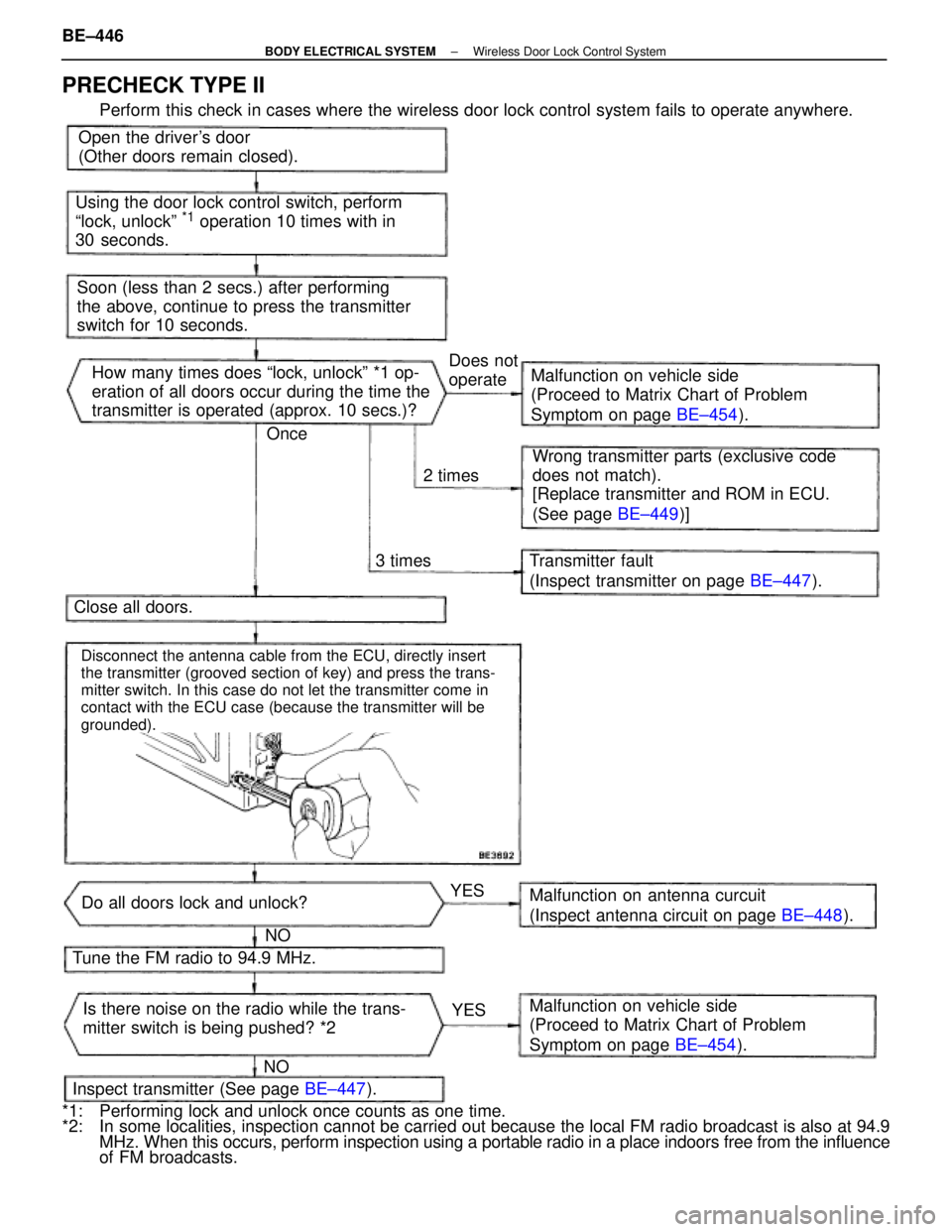
Open the driver's door
(Other doors remain closed).
Using the door lock control switch, perform
ªlock, unlockº
*1 operation 10 times with in
30 seconds.
Soon (less than 2 secs.) after performing
the above, continue to press the transmitter
switch for 10 seconds. How many times does ªlock, unlockº *1 op-
eration of all doors occur during the time the
transmitter is operated (approx. 10 secs.)? Malfunction on vehicle side
(Proceed to Matrix Chart of Problem
Symptom on page
BE±454).
Wrong transmitter parts (exclusive code
does not match).
[Replace transmitter and ROM in ECU.
(See page BE±449)]
Transmitter fault
(Inspect transmitter on page BE±447).
Close all doors.
Tune the FM radio to 94.9 MHz.
Inspect transmitter (See page BE±447).
Do all doors lock and unlock?
Is there noise on the radio while the trans-
mitter switch is being pushed? *2 Malfunction on antenna curcuit
(Inspect antenna circuit on page
BE±448).
Malfunction on vehicle side
(Proceed to Matrix Chart of Problem
Symptom on page BE±454).
3 times
2 timesDoes not
operate
YESYES
NO
NO Once
Disconnect the antenna cable from the ECU, directly insert
the transmitter (grooved section of key) and press the trans-
mitter switch. In this case do not let the transmitter come in
contact with the ECU case (because the transmitter will be
grounded).
PRECHECK TYPE II
Perform this check in cases where the wireless door lock control system fails t\
o operate anywhere.
*1: Performing lock and unlock once counts as one time.
*2: In some localities, inspection cannot be carried out because the local FM \
radio broadcast is also at 94.9 MHz. When this occurs, perform inspection using a portable radio in a place \
indoors free from the influence
of FM broadcasts.
BE±446
±
BODY ELECTRICAL SYSTEM Wireless Door Lock Control System
WhereEverybodyKnowsYourName
Page 1199 of 4087
mm in.5 0.20
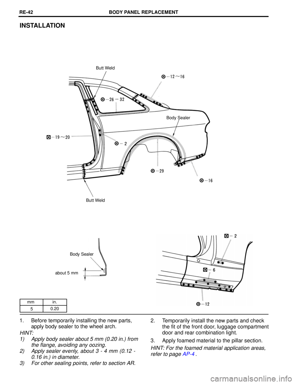
INSTALLATION
Butt Weld
Body Sealer
Butt Weld
Body Sealer
about 5 mm
1. Before temporarily installing the new parts, apply body sealer to the wheel arch.
HINT:
1) Apply body sealer about 5 mm (0.20 in.) from the flange, avoiding any oozing.
2) Apply sealer evenly, about 3 - 4 mm (0.12 - 0.16 in.) in diameter.
3) For other sealing points, refer to section AR.
2. Temporarily install the new parts and check the fit of the front door, luggage compartment
door and rear combination light.
3. Apply foamed material to the pillar section.
HINT: For the foamed material application areas, refer to page AP-4.
BODY PANEL REPLACEMENTRE-42
WhereEverybodyKnowsYourName
Page 1242 of 4087

mm in.150
200
300 5.91
7.87
11.81
Replacement parts
QUARTER PANEL
HOW TO USE THIS MANUAL
Each repair method description provided in Section RE of this manual com\
prises two pages, divided into
2 blocks (REMOVAL AND INSTALLATION) and includes illustrations to facilitate body repair.
BODY PANEL REPLACEMENT-Rear Body Components
RE-40
QUARTER PANEL (CUT)REMOVAL Cut and Join Location
200 - 300 mm
150 - 200 mm
[Cut and Join Location]
Cut and Join Location
(Cut Location for Supply Parts)
1. Cut and join the parts at the location shown above.
HINT: Make incision and bend the roof drip channel at the upper part of the cur and join location.
REPLACEMENT PARTS AND METHOD
(CUT)
Replacement method(ASSY) Assembly replacement . . . . .
(CUT) Major cutting (less than 1/2 of parts used) . . . . . .
(CUT-H) Half cutting (about 1/2 of parts used) . . . .
(CUT-P) Partial cutting (most of parts used) . . . .
PARTS LOCATION
REMOVAL DIAGRAM
Describes in detail removal of the damaged parts involving repair by cut\
ting.
REMOVAL GUIDE
Provides additional information to more efficiently help you perform the removal.
INTRODUCTIONIN-2
WhereEverybodyKnowsYourName
Page 1243 of 4087
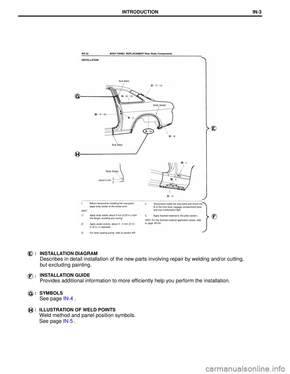
1. Before temporarily installing the new parts,apply body seater to the wheel arch.
HINT:
1) Apply body sealer about 5 mm (0.20 in.) from the flange, avoiding any oozing.
2) Apply sealer evenly, about 3 - 4 mm (0.12 - 0.16 in.) in diameter.
3) For other sealing points, refer to section AR.
RE 42 BODY PANEL REPLACEMENT-Rear Body Components
INSTALLATION
Butt Weld
Body Sealer
Butt Weld
Body Sealer
about 5 mm
2. Temporarily install the new parts and check thefit of the front door, luggage compartment door
and rear combination light.
3. Apply foamed material to the pillar section.
HINT: For the foamed material application areas, refer to page AP-00.
INSTALLATION DIAGRAM
Describes in detail installation of the new parts involving repair by we\
lding and/or cutting,
but excluding painting.
INSTALLATION GUIDE
Provides additional information to more efficiently help you perform the installation.
SYMBOLS
See page IN-4.
ILLUSTRATION OF WELD POINTS
Weld method and panel position symbols.
See page IN-5.
INTRODUCTIONIN-3
WhereEverybodyKnowsYourName