Page 1438 of 4087
 Align the camshaft knock pin with the knock pin groove of the
timing pulley, and slide on the timing pulley.
(b) Slide the timing pulley on the camshaft, f")
11. INSTALL LH CAMSHAFT TIMING PULLEY
(a) Align the camshaft knock pin with the knock pin groove of the
timing pulley, and slide on the timing pulley.
(b) Slide the timing pulley on the camshaft, facing the ªLº mark
forward.
(c) Using SST, install the pulley bolt. SST 09278±54012
Torque: 108 N Vm (1,100 kgf Vcm, 80 ft Vlbf)
12. SET NO.1 CYLINDER TO TDC/COMPRESSION
(a) Crankshaft Pulley Position:
Turn the crankshaft pulley, and align its groove with timing
mark ª0º of the No. 1 timing belt cover.
(b) (Camshaft Timing Pulley Position) Using SST, turn the camshaft timing pulley, and align the tim-
ing marks of the camshaft timing pulley and timing belt rear
plate.
SST 09278±54012
13. CONNECT TIMING BELT TO LH CAMSHAFT TIMING PULLEY
(a) Align the installation mark on the timing belt with the the end
of the hydraulic pump.
(b) Remove any oil or water on the LH camshaft timing pulley, and keep it clean.
(c) Using SST, slightly turn the LH camshaft timing pulley
clockwise. Align the installation mark on the timing belt with
the timing mark of the camshaft timing pulley, and hang the
timing belt on the LH camshaft timing pulley.
SST 09278±54012
EG±62
±
1UZ±FE ENGINE ENGINE MECHANICAL
WhereEverybodyKnowsYourName
Page 1439 of 4087
 Using SST, align the timing marks of the LH camshaft timingpulley and timing belt rear plate.
SST 09278±54012
(e) C h e c k t h a t t h e t i m i n g b e l t h a s t e n s i o n b e t w e e n")
(d) Using SST, align the timing marks of the LH camshaft timingpulley and timing belt rear plate.
SST 09278±54012
(e) C h e c k t h a t t h e t i m i n g b e l t h a s t e n s i o n b e t w e e n t h e
crankshaft timing pulley and LH camshaft timing pulley.
14. CONNECT TIMING BELT TO RH CAMSHAFT TIMING PULLEY
(a) Remove any oil or water on the RH camshaft timing pulley
and water pump pulley, and keep them clean.
(b) Using SST, slightly turn the RH camshaft timing pulley clockwise. Align the installation mark on the timing belt with
the timing mark of the camshaft timing pulley, and hang the
timing belt on the RH camshaft timing pulley.
SST 09278±54012
(c) Using SST, align the timing marks of the RH camshaft timing pulley and timing belt rear plate.
SST 09278±54012
(d) Check that the timing belt has tension between the RH camshaft timing pulley and LH camshaft timing pulley.
15. SET TIMING BELT TENSIONER
(a) Using a press, slowly press in the push rod using 981 ± 9,807
N (100 ± 1,000 kgf, 220 ± 2,205 lbf) of force.
(b) Align the holes of the push rod and housing, pass a 1.27 mm hexagon wrench through the holes to keep the setting
position of the push rod.
(c) Release the press.
(d) Install the dust boot to the belt tensioner.
±
1UZ±FE ENGINE ENGINE MECHANICALEG±63
WhereEverybodyKnowsYourName
Page 1465 of 4087
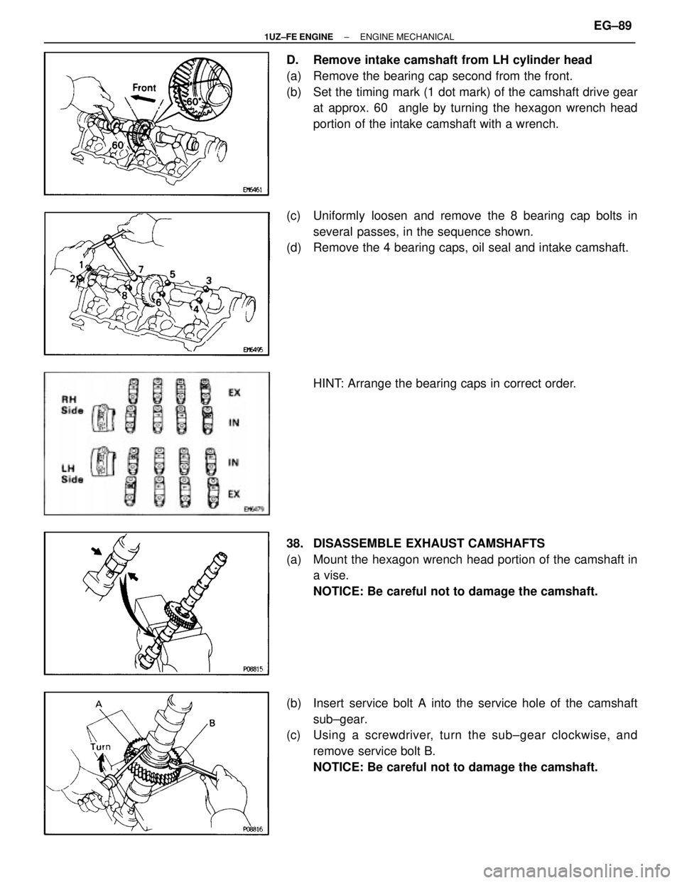
D. Remove intake camshaft from LH cylinder head
(a) Remove the bearing cap second from the front.
(b) Set the timing mark (1 dot mark) of the camshaft drive gearat approx. 60 � angle by turning the hexagon wrench head
portion of the intake camshaft with a wrench.
(c) Uniformly loosen and remove the 8 bearing cap bolts in several passes, in the sequence shown.
(d) Remove the 4 bearing caps, oil seal and intake camshaft.
HINT: Arrange the bearing caps in correct order.
38. DISASSEMBLE EXHAUST CAMSHAFTS
(a) Mount the hexagon wrench head portion of the camshaft in a vise.
NOTICE: Be careful not to damage the camshaft.
(b) Insert service bolt A into the service hole of the camshaft sub±gear.
(c) Using a screwdriver, turn the sub±gear clockwise, and
remove service bolt B.
NOTICE: Be careful not to damage the camshaft.
±
1UZ±FE ENGINE ENGINE MECHANICALEG±89
WhereEverybodyKnowsYourName
Page 1659 of 4087
 Remove the 12 bolts and four nuts.
(b) Remove the cylinder head covers and gaskets.
10. SET NO. 1 CYLINDER TO TDC/COMPRESSION (a) Turn th")
9. REMOVE NO. 3, NO. 1 AND NO. 2 CYLINDER HEADCOVERS
(a) Remove the 12 bolts and four nuts.
(b) Remove the cylinder head covers and gaskets.
10. SET NO. 1 CYLINDER TO TDC/COMPRESSION (a) Turn the crankshaft pulley and align its groove withtiming mark º0º of the No. 1 timing belt cover.
NOTICE: Always turn the crankshaft clockwise.
(b) Check that the timing marks of the camshaft timing pulleys are aligned with the timing marks of the No. 4
timing belt cover.
If not, turn the crankshaft one revolution (360 5).
11. INSPECT VALVE CLEARANCE (a) Uniformly tighten the bearing cap bolts in severalpasses.
Torque: 20 N Vm (200 kgf Vcm, 14 ft Vlbf)
(b) Check only those valves indicated in the illustration.
w Using a feeler gauge, measure the clearance
between the valve lifter and camshaft.
w Record the valve clearance measurements of
those that are out of specification. They will be used
later to determine the required replacement
adjusting shim.
Valve clearance (Cold):
Intake 0.15±0.25 mm (0.006±0.010 in.)
Exhaust 0.25±0.35 mm (0.010±0.014 in.)
EM±12±
ENGINE MECHANICAL Engine Tune±Up
WhereEverybodyKnowsYourName
Page 1691 of 4087
1. REMOVE WATER PUMP PULLEY AND RADIATOR (See steps 1 to 3, 6 and 7 on pages EM±64 and 66)
2. REMOVE NO. 3 AND NO. 2 TIMING BELT COVERS (a) R")
REMOVAL OF TIMING BELT
(See Components on page EM±23)1. REMOVE WATER PUMP PULLEY AND RADIATOR (See steps 1 to 3, 6 and 7 on pages EM±64 and 66)
2. REMOVE NO. 3 AND NO. 2 TIMING BELT COVERS (a) Remove the oil filler cap.
(b) Using a 5 mm hexagon wrench, remove the nine bolts,No. 3, No. 2 timing belt covers and gasket.
3. REMOVE DRIVE BELT TENSIONER Remove the three bolts and tensioner.
4. SET NO. 1 CYLINDER TO TDC/COMPRESSION (a) Turn the crankshaft pulley and align its groove withtiming mark º0º of the No. 1 timing belt cover.
NOTICE: Always turn the crankshaft clockwise.
(b) Check that the timing marks of the camshaft timing pulleys are aligned with the timing marks of the No. 4
timing belt cover.
If not, turn the crankshaft one revolution (360 5).
5. REMOVE TIMING BELT FROM CAMSHAFT TIMING PULLEYS
HINT: (Re±using timing belt)
Place matchmarks on the timing belt and camshaft timing
pulleys as shown in the illustration.
EM±24
±
ENGINE MECHANICAL Timing Belt
WhereEverybodyKnowsYourName
Page 1722 of 4087
 Align the knock pin on the camshaft with the knock pingroove of the timing pulley.
(b) Slide the timing pulley, facing the ºLº mark forward.
(c) Using S")
11. INSTALL LH CAMSHAFT TIMING PULLEY(a) Align the knock pin on the camshaft with the knock pingroove of the timing pulley.
(b) Slide the timing pulley, facing the ºLº mark forward.
(c) Using SST, install and torque the pulley bolt.
SST 09278±54012
Torque: 108 N Vm (1,100 kgf Vcm, 80 ft Vlbf)
12. SET NO.1 CYLINDER TO TDC/COMPRESSION
(a) (Crankshaft Pulley Position)Turn the crankshaft pulley, and align its groove with the
ºOº timing mark of the No.1 timing belt cover.
(b) (Camshaft Timing Pulley Position) Using SST, t urn the camshaft timing pulley, and align the
timing marks of the camshaft timing pulley and timing
belt rear plate.
SST 09278±54012
13. INS TALL TIMING BE LT TO LH CAMS HAFT TIMING PULLEY
(a) Align the installation mark on the timing belt with the end
of the hydraulic pump.
(b) Remove any oil or water on the LH camshaft timing pulley, and keep it clean.
(c) Using SST, slightly turn the LH camshaft timing pulley
clockwise. Align the installation mark on the timing belt
with the timing mark of the camshaft timing pulley, and
hang the timing belt on the LH camshaft timing pulley.
SST 09278±54012
±
ENGINE MECHANICAL Timing BeltEM±49
WhereEverybodyKnowsYourName
Page 1723 of 4087
 Using SST, align the timing marks of the LH camshaftpulley and timing belt rear plate.
SST 09278±54012
(e) Check that the timing belt has tension between the crankshaft timing pulley and LH c")
(d) Using SST, align the timing marks of the LH camshaftpulley and timing belt rear plate.
SST 09278±54012
(e) Check that the timing belt has tension between the crankshaft timing pulley and LH camshaft timing pulley.
14. INSTALL TIMING BELT TO RH CAMSHAFT TIMING PULLEY
(a) Remove any oil or water on the RH camshaft timing andwater pump pulley, and keep them clean.
(b) Using SST, slightly turn the RH camshaft timing pulley clockwise. Align the installation mark on the timing belt
with the timing mark of the camshaft timing pulley, and
hang the timing belt on the RH camshaft timing pulley.
SST 09278±54012
(c) Using SST, align the timing marks of the RH camshaft pulley and timing belt rear plate.
SST 09278±54012
(d) Check that the timing belt has tension between the RH
camshaft timing pulley and LH camshaft pulley.
15. SET TIMING BELT TENSIONER (a) Using a press, slowly press in the push rod using981±9,807 N (100±1,000 kgf, 220±2,205 lbf) of
pressure.
(b) Align the holes of the push rod and housing, pass a 1.27
mm hexagon wrench through the holes to keep the
setting position of the push rod.
(c) Release the press.
(d) Install the dust boot to the tensioner.
EM±50
±
ENGINE MECHANICAL Timing Belt
WhereEverybodyKnowsYourName
Page 1913 of 4087
(b) Insert a 0.40 mm (0.016 in.) feeler gauge, between thethrottle stop screw and stop lever.
(c) Connect the test probe of an ohmmeter to the terminals
IDL1 and E2 of the sensor.
(d) Gradually turn the sensor clockwise until the ohmmeter deflects, and secure it with the two set screws.
(e) Recheck the continuity between terminals IDL1 and E2.
Clearance between
lever and stop screwContinuity (IDL1±E2)
0.40 mm (0.016 in.)Continuity
0.65 mm (0.026 in.)No continuity
3. (w/ TRAC) INSPECT SUB±THROTTLE ACTUATOR, SUBTHROTTLE
VALVE AND SUB±THROTTLE POSITION SENSOR
A. Inspect sub±throttle actuator Using an ohmmeter, measure the resistance between the ter-
minals (ACM±A and �, BCM±B and B).
Resistance: 0.5±1.0 �
If the resistance is not as specified, replace the actuator
valve.
B. Inspect sub±throttle actuator Remove the three screws and sub±throttle actuator.
FI±74
EFI SYSTEM
± Air Induction System (Throttle Body)
WhereEverybodyKnowsYourName
 Insert a 0.40 mm (0.016 in.) feeler gauge, between thethrottle stop screw and stop lever.
(c) Connect the test probe of an ohmmeter to the terminals
IDL1 and E2 of the sensor.
(d) Gradually t")