Page 2981 of 4087
POWER STEERING PUMP
DISASSEMBLY
SR0G7±02
1. MOUNT POWER STEERING PUMP IN VISE
NOTICE: Do not tighten the vise too tight.
2. REMOVE PUMP PULLEY
(a) Using SST, remove the pulley set nut.SST 09278±54012
(b) Remove the pulley.
3. REMOVE SUCTION PORT UNION
(a) Remove the 2 bolts and union.
(b) Remove the O±ring from the union.
4. REMOVE PRESSURE PORT UNION, FLOW CONTROL
VALVE AND SPRING
(a) Remove the pressure port union.
(b) Remove the O±ring from the union.
(c) Remove the flow control valve and spring.
5. REMOVE SPRING SEAT
(a) Using snap ring pliers, remove the snap ring. HINT: The snap ring is easier to remove if the spring seat is
pressed down slightly.
(b) Temporarily install a bolt to the seat and pull out it. HINT: Use a bolt with diameter 6 mm (0.24 in.) and pitch 1.0
mm (0.039 in.).
(c) Remove the O±ring from the seat.
±
STEERING POWER STEERINGSR±121
WhereEverybodyKnowsYourName
Page 2984 of 4087
Maximum clearance:0.07 mm (0.0028 in.)
If more than maximum, replace the entire power steering
pump.
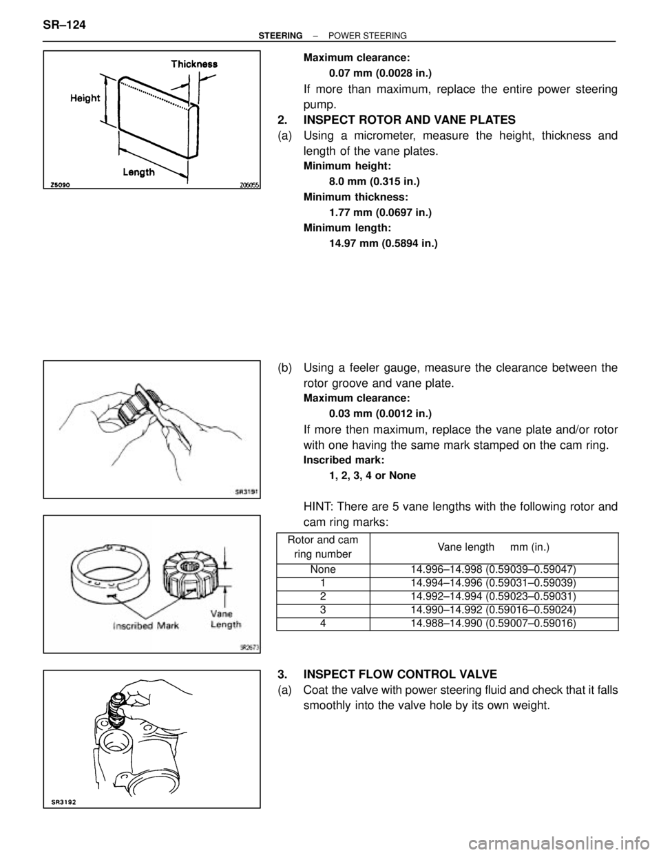
2. INSPECT ROTOR AND VANE PLATES
(a) Using a micrometer, measure the height, thickness and length of the vane plates.
Minimum height:
8.0 mm (0.315 in.)
Minimum thickness: 1.77 mm (0.0697 in.)
Minimum length:
14.97 mm (0.5894 in.)
(b) Using a feeler gauge, measure the clearance between therotor groove and vane plate.
Maximum clearance:
0.03 mm (0.0012 in.)
If more then maximum, replace the vane plate and/or rotor
with one having the same mark stamped on the cam ring.
Inscribed mark:1, 2, 3, 4 or None
HINT: There are 5 vane lengths with the following rotor and
cam ring marks:
������� �������Rotor and camring number���������������� ����������������Vane length mm (in.)
������� �������None���������������� ����������������14.996±14.998 (0.59039±0.59047)������� �������1���������������� ����������������14.994±14.996 (0.59031±0.59039)������� �������2���������������� ����������������14.992±14.994 (0.59023±0.59031)
������� �������3���������������� ����������������14.990±14.992 (0.59016±0.59024)
������� �������4���������������� ����������������14.988±14.990 (0.59007±0.59016)
3. INSPECT FLOW CONTROL VALVE
(a) Coat the valve with power steering fluid and check that it falls smoothly into the valve hole by its own weight.
SR±124
±
STEERING POWER STEERING
WhereEverybodyKnowsYourName
Page 2989 of 4087
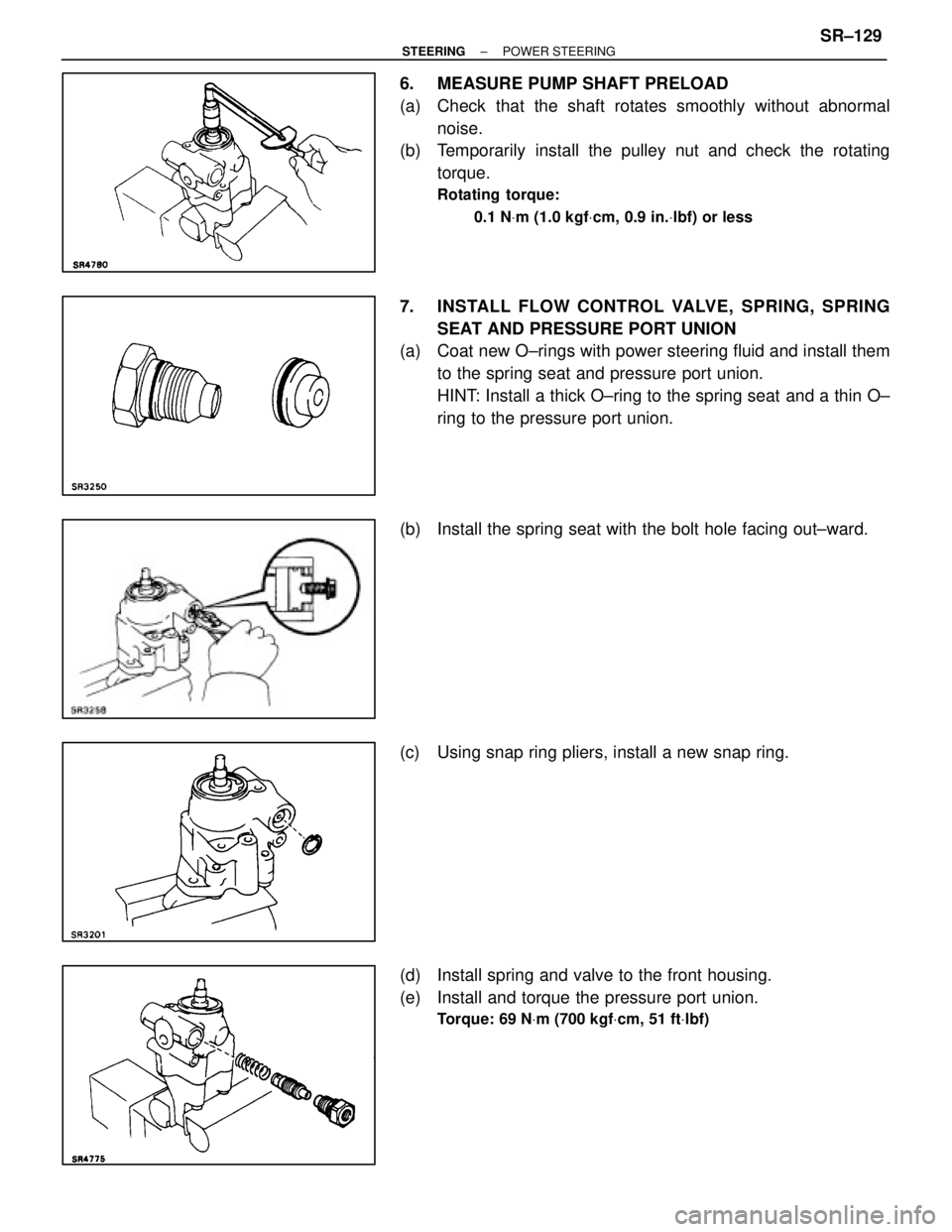
6. MEASURE PUMP SHAFT PRELOAD
(a) Check that the shaft rotates smoothly without abnormalnoise.
(b) Temporarily install the pulley nut and check the rotating
torque.
Rotating torque:
0.1 N Vm (1.0 kgf Vcm, 0.9 in. Vlbf) or less
7. INSTALL FLOW CONTROL VALVE, SPRING, SPRING
SEAT AND PRESSURE PORT UNION
(a) Coat new O±rings with power steering fluid and install them
to the spring seat and pressure port union.
HINT: Install a thick O±ring to the spring seat and a thin O±
ring to the pressure port union.
(b) Install the spring seat with the bolt hole facing out±ward.
(c) Using snap ring pliers, install a new snap ring.
(d) Install spring and valve to the front housing.
(e) Install and torque the pressure port union.
Torque: 69 N Vm (700 kgf Vcm, 51 ft Vlbf)
±
STEERING POWER STEERINGSR±129
WhereEverybodyKnowsYourName
Page 3869 of 4087

27
Position of Parts in Engine Compartment
I 1 ISC Valve S 3Speed Sensor No. 1
I 2 Igniter S 4 Speed Sensor No. 2 (for ECT)
I 4 Ignition Coil S 6 Starter
I 6 Injector No. 1 S 7 Starter
I 7 Injector No. 2 S 8 Sub Throttle Actuator
I 8 Injector No. 3 S 9 Sub Throttle Position Sensor
I 9 Injector No. 4
I 10 Injector No. 5 T 1 Theft Deterrent Horn
I 11 Injector No. 6 T 2 Throttle Position Sensor T 3 Traction Brake Actuator
K 1 Knock Sensor No. 1 (on Front Side) T 4 Traction Brake Actuator
K 2 Knock Sensor No. 2 (on Rear Side) T 5 Traction pump and Motor
N 1 Neutral Start SW, Back±Up Light SW and A/T Indicator SW V 1 VSV (for EGR) (Exc. USA Spec) (for A/T) V 2 VSV (for EVAP)
N 2 Noise Filter (for Defogger System) V 4 VSV (for Water Valve)
N 3 Noise Filter (for Ignition System) V 7 VSV (for Intake Control Valve)
O 2 Oil Pressure SW W 1 Washer Level SW
O 3 Oxygen Sensor Main No. 1 (on Front Side) W 2 Washer Motor
O 4 Oxygen Sensor Main No. 2 (on Rear Side) W 3 Water Temp. Sender W 5 Wiper Motor
P 1 PPS Solenoid
P 20 Power Steering Pressure SW
WhereEverybodyKnowsYourName