Page 2770 of 4087

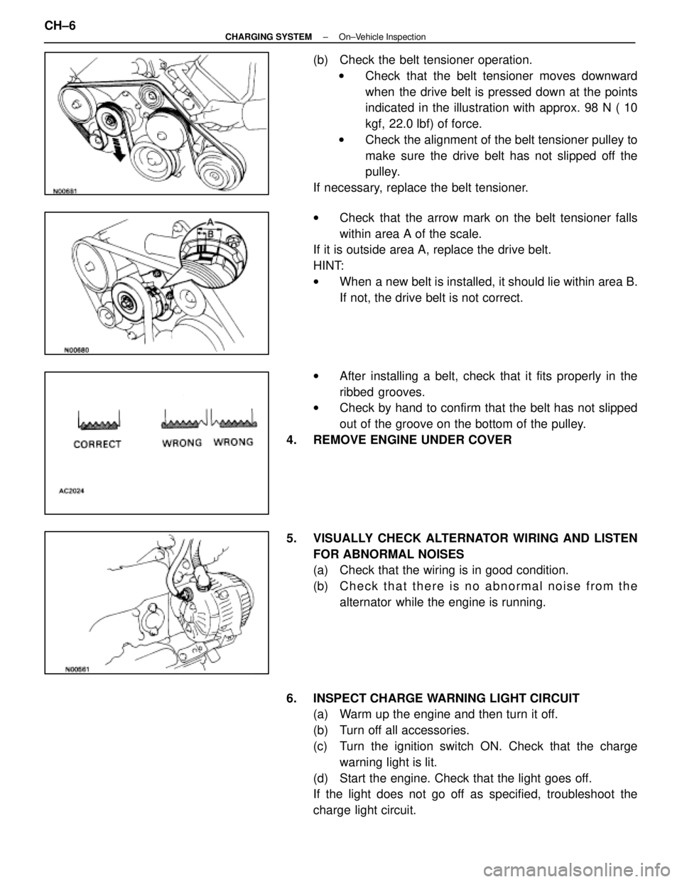
(b) Check the belt tensioner operation.w Check that the belt tensioner moves downward
when the drive belt is pressed down at the points
indicated in the illustration with approx. 98 N ( 10
kgf, 22.0 lbf) of force.
w Check the alignment of the belt tensioner pulley to
make sure the drive belt has not slipped off the
pulley.
If necessary, replace the belt tensioner.
w Check that the arrow mark on the belt tensioner falls
within area A of the scale.
If it is outside area A, replace the drive belt.
HINT:
w When a new belt is installed, it should lie within area B.
If not, the drive belt is not correct.
w After installing a belt, check that it fits properly in the
ribbed grooves.
w Check by hand to confirm that the belt has not slipped
out of the groove on the bottom of the pulley.
4. REMOVE ENGINE UNDER COVER
5. VISUALLY CHECK ALTERNATOR WIRING AND LISTEN FOR ABNORMAL NOISES
(a) Check that the wiring is in good condition.
(b) C h e c k t h a t t h e r e i s n o a bnormal noise from the
alternator while the engine is running.
6. INSPECT CHARGE WARNING LIGHT CIRCUIT (a) Warm up the engine and then turn it off.
(b) Turn off all accessories.
(c) Turn the ignition switch ON. Check that the charge
warning light is lit.
(d) Start the engine. Check that the light goes off.
If the light does not go off as specified, troubleshoot the
charge light circuit.
CH±6
±
CHARGING SYSTEM On±Vehicle Inspection
WhereEverybodyKnowsYourName
Page 2773 of 4087
ALTERNATOR
COMPONENTS FOR REMOVAL AND
INSTALLATION
REMOVAL OF ALTERNATOR
1. DISCONNECT CABLE FROM NEGATIVE TERMINAL OFBATTERY
CAUTION: Work must be started after approx. 20 se-
conds or longer from the time the ignition switch is
turned to the ºLOCKº position and the negative (±) termi-
nal cable is disconnected from the battery.
2. REMOVE ENGINE UNDER COVER
3. REMOVE DRIVE BELT
Loosen the belt tension by turning the drive belt tensioner
counterclockwise, and remove the drive belt.
HINT: The pulley bolt for the belt tensioner has a left±hand
thread.
±
CHARGING SYSTEM AlternatorCH±9
WhereEverybodyKnowsYourName
Page 2784 of 4087
INSTALLATION OF ALTERNATOR
(See Components on page CH±9)
1. INSTALL ALTERNATOR (a) Install the alternator and A/T oil cooler bracket with the
bolt and nut.
Torque: 37 N Vm (380 kgf Vcm, 27 ft Vlbf)
(b) Connect the alternator connector.
(c) Connect the alternator wire with the nut and cap.
2. INSTALL DRIVE BELT Install the drive belt by turning the drive belt tensioner coun-
terclockwise.
HINT: The pulley bolt for the belt tensioner has a left±hand
thread.
3. CONNECT CABLE TO NEGATIVE TERMINAL OF BATTERY
4. PERFORM ON±VEHICLE INSPECTION (See steps 6 to 8 on pages CH±6 to 8)
5. INSTALL ENGINE UNDER COVER
CH±20
±
CHARGING SYSTEM Alternator
WhereEverybodyKnowsYourName
Page 3961 of 4087

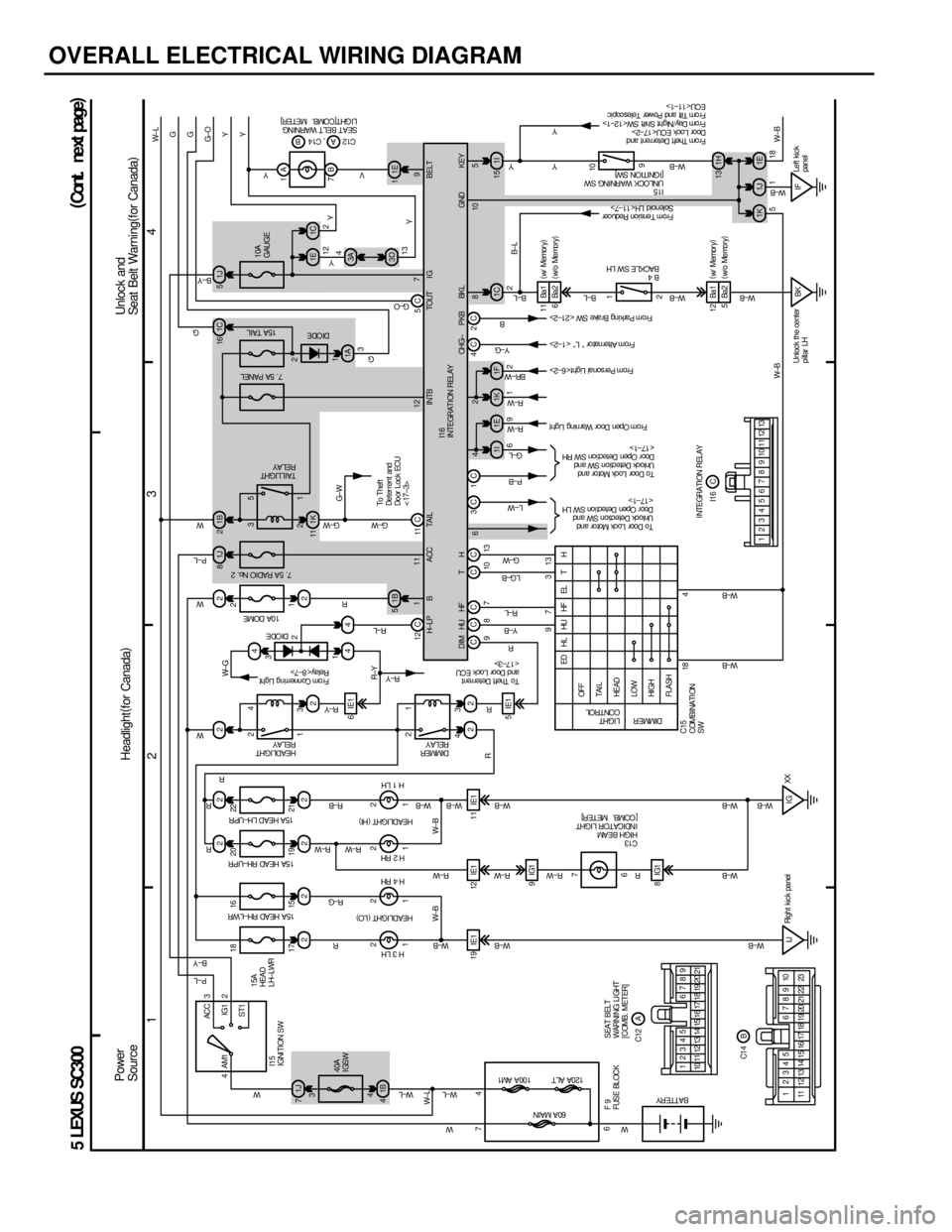
OVERALL ELECTRICAL WIRING DIAGRAM
1234
5 LEXUS SC300
1J
7 22 2 21J
81B2
4
1B
5
1B
4 1K
11
22 22
22
44
1I 1E
3 1
4 2 3
4
1 2 23
1
5
4
ACC
IG1
ST1
AM1 3
2
1 21 2 1
21
2
19 IE1 12 IE1 11 IE1 5IE1 6IE1
9IG1
4
7
6 4
15 19 21 1
3 16 20 22 2
18 497 313
6 7
IJ 8IG1 1J
5
3A 1E 1C
1A
1I
15
1C
1F
1K 3D
7B 1A
2 1 9
10
BK IF 1H
1K 1J 1E W± BY Y
G± O G
G
W± L
Y
Y
W±B
R
W±B W±B R±YW± G
G± W
W± LW± L
W± L W
W± B
R±W W± B
W± B
R
R
LG±B G±W
L±W P± B
G±L
R± W
R± W
BR± W
B±L
B± L
W± B
W± B
W±B W±B W±B W±B W±B
W± B W± B
R±W
R±W
R
W±B R±B R± W
R± W R±G
R
W
G± W
G± W R
R R
W
P±L W
G G
P±L
B±Y
W
R± Y R±L R
Y VPower
Source
F9
FUSE BL OCK60A MAIN
100A AM1
120A ALT
22W
R±Y
TH
15A
HEAD
LH±LWR
15A HEAD RH±LWR
15A HEAD RH±UPR 15 A HEA D L H± UP R
40A
IGSW
H3LH
H4 RH
H2 RH H1LH
HEADLIGHT
(
LO )
HEADLIGHT (
HI )
DIMMER
RE LA Y HEADLIGHT
RELAY
Fr om Connerring Light
Relay< 8±7> DI ODE10A DOME
7. 5A RADIO No. 2
LIGHT
CONTROL
DIMMER
OFF
TAI L
HE AD
LOW
HI GH
FLASH ED HL HU HF EL T H
C15
COMBINATI ON
SW
BATTERY
C13
HIGH BEAM
I NDI CA TOR L I GHT
[COMB. METER]
To Door Lock Mot or and
Unlock Detection SW and
Doo r Open De t ect i on S W LH
< 17±1>
To Door Lock Mot or and
Unlock Detection SW and
Doo r Open De t ect i on S W RH
< 17±1> From Open Door War ning Light
From Per sonal Light< 6±2>
B4
BACKLE SW LH
I15
UNLOCK WARNING SW
[IGNITION SW] SEAT BELT WARNI NG
LI GHT[ COMB. MET ER]
5118
TAIL LIGHT
RELAY
To Thef t
Deter rent and
Do or L oc k ECU
< 17±3>
7. 5A PANEL15A TAIL
10A
GAUGE
3 12 2
13 4Y
BELT
H± LP B A CC TA I L I NTB I G
BKL KEY
12 2
9
To Thef t Deter rent
and Door Loc k ECU
< 17±3>
I15
IGNITION SW
I16
I NTEGRAT I ON REL AY
DIM TOUT
HF
HU
Y± B
R±L
CHG± P KBY±G
B
From Alternator º Lº < 1±2>
From Park ing Br ake SW < 21±2>
1 3 2
B±Y
G± O
1C
16DI ODE
1E
1
9
C1 2 , C1 4 AB
6
From Tens ion Reducer
Solenoid LH< 11±7>
Fr om Thef t Deter rent and
Door Loc k ECU< 17±2>
Fr om Day /Night Shift SW< 12±1>
Fr om Tilt and Power Teles copic
ECU< 11±1> Y
Y
W±B
12C 11C 5C
CCC CC 4C2C 9 8 7 10 13 111 12 7
642 8 105 GND
I NTEGRATI ON REL AY
SEAT BELT
WARNING LIGHT
[COMB. METER]
10 11 12 13 17 18 19 20 21 12345 6789
14 15 16
17 18
1 2345 6789 10
23
22
21
20
19
15
14
13
12
11 16 C
A
B I16
C12
C1 4
Headlight (
for Canada ) Unlock and
Seat Belt Warning
(
for Canada )
(
Cont . ne xt pa ge )
2
1
3C 1C
13
Y
12345678910111213
18
17
IG
W±B
6Ba2Ba 1
11
5Ba2 Ba 1
12 (
w/ Memor y )
( w/o Memory )
B±L
( w/ Memor y )
( w/o Memory )
XX
Right kic k panel
Unlock the center
pillar LHLeft kic k
panel
WhereEverybodyKnowsYourName