Page 636 of 4087

21CD playerMAGAZINE IS INSERTED, BUT DISPLAY DOES
NOT INDICATE ºCDº
Is radio operating normally?
Is there battery voltage between the following
terminals with connector connected?
� Radio receiver assembly C12 ± ground
Wire harness faulty.Radio receiver assembly faulty.
Go to No. 1.
Is there battery voltage between the following
terminals with connector connected?
� Radio receiver assembly C12 ± CD auto
changer A3
Is there battery voltage between the following
terminals with connector connected?
� Radio receiver assembly C3 ± CD auto changer
B1
� Radio receiver assembly C8 ± CD auto changer
B3
� Radio receiver assembly C9 ± CD auto changer
B2
� Radio receiver assembly C10 ± CD auto changer
B10
Is there battery voltage between the following
terminals with connector disconnected?
� Radio receiver assembly C3 ± ground
� Radio receiver assembly C8 ± ground
� Radio receiver assembly C9 ± ground
� Radio receiver assembly C10 ± ground
Temporarily install another CD auto changer.
Functions OK? CD auto changer faulty. Wire harness faulty.
Wire harness faulty.
Radio receiver assembly faulty
BE±250±
BODY ELECTRICAL SYSTEM AUDIO SYSTEM
WhereEverybodyKnowsYourName
Page 637 of 4087

Is radio operating normally?Wire harness faulty.
Is there battery voltage between the following ter-
minals with connector conn")
22CD playerDISPLAY INDICATES, BUT NO SOUND IS
PRODUCED (EXCEPT WOOFER)
Is radio operating normally?Wire harness faulty.
Is there battery voltage between the following ter-
minals with connector connected?
� Power amplifier A14 ± ground
� Power amplifier A10 ± ground
Wire harness faulty.
Is there battery voltage between the following ter-
minals with connector connected?
�
Power amplifier A6 ± ground
Is there battery voltage between the following ter-
minals with connector connected?
� Power amplifier A7 ± ground Is there battery voltage between the following ter-
minals with connector disconnected?
�
Radio receiver assembly B6 ± Power switch 13.
Is there battery voltage between the following ter-
minals with connector disconnected?
�
Radio receiver assembly B1±Power switch 14
� Radio receiver assembly B3±Power switch 11
Wire harness faulty.
Power switch faulty.
Wire harness faulty.
Radio receiver assem-
bly faulty. Wire harness faulty.
Power switch faulty.
Is resistance value about 50 k � between terminals
B3±B6 of radio receiver assembly?
Temporarily install another CD auto changer.
Functions OK? CD auto changer faulty.Is there continuity between the following terminals
with connector disconnected?
�
Radio receiver assembly A1±Power amplifier A6.
When the volume switch is turned from minimum to
maximum, does resistance between terminals
B1±B3 of radio receiver assembly changer from 0
to 50 k
�� Radio receiver assembly faulty.
Radio receiver assembly faulty.
±
BODY ELECTRICAL SYSTEM AUDIO SYSTEMBE±251
WhereEverybodyKnowsYourName
Page 639 of 4087
Temporarily install another power amplifier.
Function is OK?Radio receiver assembly faulty. Power amplifier faulty.
24CD playerVOLUME FAINT (EXCEPT WOOFER)
Is radio operating normally?
When the volume switch is turned from minimum to
maximum, does resistance between terminals
B1±B3 of radio receiver assembly changer from 0
to 50 k �� Radio receiver assembly faulty.
Power switch faulty.
Wire harness faulty.
Power amplifier faulty.
Radio receiver assembly faulty.
*Is there battery voltage between the following
terminals with connector disconnected?
�
Radio receiver assembly D3 ± ground
Temporarily install another power amplifier.
Function is OK?
±
BODY ELECTRICAL SYSTEM AUDIO SYSTEMBE±253
WhereEverybodyKnowsYourName
Page 640 of 4087
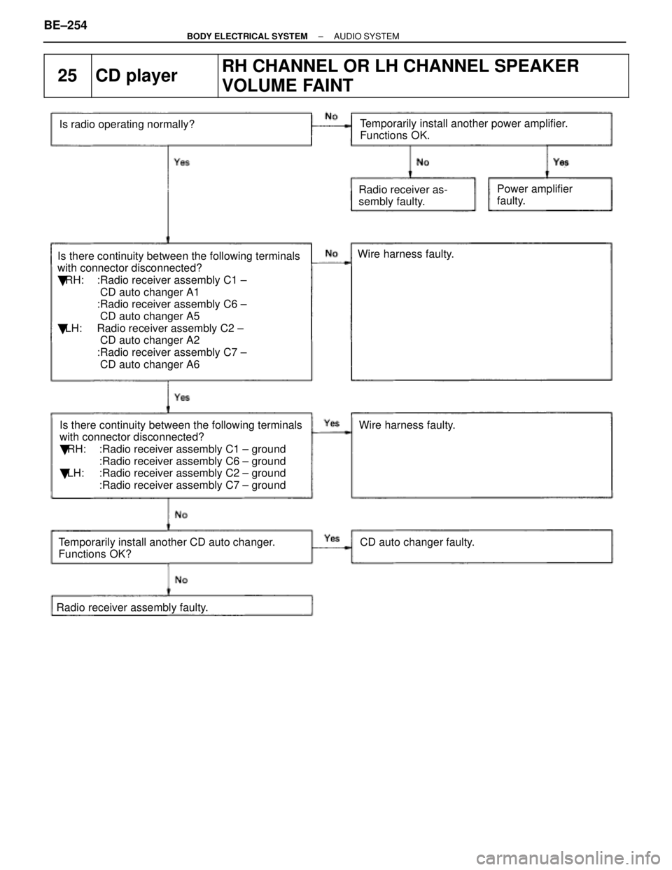
25CD playerRH CHANNEL OR LH CHANNEL SPEAKER
VOLUME FAINT
Is there continuity between the following terminals
with connector disconnected?
� RH: :Radio receiver assembly C1 ±
CD auto changer A1
:Radio receiver assembly C6 ±
CD auto changer A5
� LH: Radio receiver assembly C2 ±
CD auto changer A2
:Radio receiver assembly C7 ±
CD auto changer A6 Radio receiver as-
sembly faulty.
Is radio operating normally?
Wire harness faulty.
Wire harness faulty.
Is there continuity between the following terminals
with connector disconnected?
� RH: :Radio receiver assembly C1 ± ground
:Radio receiver assembly C6 ± ground
� LH: :Radio receiver assembly C2 ± ground
:Radio receiver assembly C7 ± ground
Temporarily install another CD auto changer.
Functions OK? CD auto changer faulty.
Radio receiver assembly faulty. Power amplifier
faulty.
Temporarily install another power amplifier.
Functions OK.
BE±254±
BODY ELECTRICAL SYSTEM AUDIO SYSTEM
WhereEverybodyKnowsYourName
Page 643 of 4087
28CD playerSOUND QUALITY POOR
Is radio operating normally?
Is speaker properly installed? Temporarily install another speaker
Functions OK? Temporarily install another CD auto changer.
Functions OK?
Temporarily install another power amplifier.
Functions OK? Radio receiver assembly faulty. Speaker faulty. Speaker installation faulty
Power amplifier faulty. Radio receiver assem-
bly faulty CD changer faulty.
29CD playerVOLUME REMAINS AT MAXIMUM LEVEL
Is radio operating normally?
Radio receiver assembly faulty.
Wire harness faulty.
Is there continuity between the following terminals
with connector disconnected?
� Radio receiver assembly B1 ± Power switch 14
� Radio receiver assembly B3 ± Power switch 11
Power switch faulty.
Radio receiver assembly faulty.
When the volume switch is turned from minimum to
maximum, does resistance between terminal 11±14
of power switch changes from 0 to 50 k
�?
±
BODY ELECTRICAL SYSTEM AUDIO SYSTEMBE±257
WhereEverybodyKnowsYourName
Page 644 of 4087
30NoiseNOISE PRODUCED BY VIBRATION OR SHOCK
WHILE DRIVING
Is radio properly installed?
Is radio receiver assembly properly installed?
*1 Is radio power amplifier properly installed?
*2 Is woofer amplifier properly installed?*1 Is CD auto changer properly installed?
With vehicle stopped, lightly tap each part.
Is noise produced? Speaker installation faulty.
Radio receiver assembly installation faulty.
Power amplifier installation faulty.
Woofer amplifier installation faulty.
CD auto changer installation faulty. Each part faulty.
Noise produced by static electricity is accululating in the vehicle body\
.
BE±258±
BODY ELECTRICAL SYSTEM AUDIO SYSTEM
WhereEverybodyKnowsYourName
Page 1249 of 4087

Power Seat ECU
(For Drivers Seat) CD Automatic Changer
Wireless Door Lock ECU
Moon Roof Control Relay
Locations of ECU")
Fuel Pump ECUAuto Antenna Motor and Relay
Power Seat ECU
(For Passenger's Seat)
Power Seat ECU
(For Driver's Seat) CD Automatic Changer
Wireless Door Lock ECU
Moon Roof Control Relay
Locations of ECUs (Cont'd)
Many ECUs are mounted in this vehicle.
Take the following precautions during body repair to prevent damage to th\
e ECUs.
�
Before starting electric welding operations, disconnect the negative (-\
) terminal cable from the battery.
When the negative (-) terminal cable is disconnected from the battery, memory of the clock and audio
systems will be cancelled. So before starting work, make a record of the\
contents memorized by each
memory system. Then when work is finished, reset the clock and audio sys\
tems as before.
When the vehicle has tilt and telescopic steering, power seat and outsid\
e rear view mirror, which are all
equipped with memory function, it is not possible to make a record of th\
e memory contents.
So when the operation is finished, it will be necessary to explain this \
fact to the customer, and request
the customer to adjust the features and reset the memory.
� Do not expose the ECUs to ambient temperatures above 80 °C (176 °F).
NOTICE: If it is possible the ambient temperature may reach 80°C (176°F) or, more, remove the ECUs
from the vehicle before starting work.
� Be careful not to drop the ECUs and not to apply physical shocks to them\
.
5. COMPONENTS ADJACENT TO THE BODY PANELS
Various types of component parts are mounted directly on or adjacently to\
the body panels.
Strictly observe the following precautions to prevent damaging these com\
ponents and the body panels
during handling.
�Before repairing the body panels, remove their adjacent components or ap\
ply protective covers over
the components.
� Before prying components off using a screwdriver or a scraper, etc., attach protective tape to the tool
tip or blade to prevent damaging the components and the body paint.
� Before removing components from the outer surface of the body, attach protective tape to the body to
ensure no damage to painted areas.
HINT: Apply touch-up paint to any damaged paint surfaces.
�Before drilling or cutting sections, make sure that there are no wires, \
hoses, etc., on the reverse side.
INTRODUCTIONIN-9
WhereEverybodyKnowsYourName
Page 1891 of 4087
 Remove the six nuts and five bolts holding the intake airconnector to the air intake chamber.
(c) Disconnect the check connector and harness protector from the air intake chamber.
(d) Remove")
(b) Remove the six nuts and five bolts holding the intake airconnector to the air intake chamber.
(c) Disconnect the check connector and harness protector from the air intake chamber.
(d) Remove the five bolts, two nuts, intake air chamber and two gaskets.
INSPECTION OF ACOUSTIC CONTROL
INDUCTION SYSTEM (ACIS)
1. INSPECT IACV (a) With 53.3 kPa (400 mmHg, 15.75 in.Hg) of vacuumapplied to the actuator, check that the actuator rod
moves.
(b) One minute after applying the vacuum in (a), check that the actuator rod does not return.
If the operation is not as specified, turn the adjusting screw.
2. INSPECT VACUUM TANK (a) Check that air flows from port A to port B.
(b) Check that air does not flow port B to port A.
(c) Plug port B with your finger, and apply 53.3 kPa (400
mmHg, 15.75 in.Hg) of vacuum to port A, and check that
there is no changer in vacuum after one minute.
If the operation is not as specified, replace the vacuum tank.
±
EFI SYSTEMFI±59Air Induction System (Acoustic Control Induction System (ACIS)
WhereEverybodyKnowsYourName

Is radio operating normally?
When the volum")