Page 966 of 4087
WIRING DIAGRAM
DTC61ABS & TRAC ECU Communication Circuit
Malfunction
CIRCUIT DESCRIPTION
DTC No.DTC Detecting ConditionTrouble Area
61Malfunction in ABS & TRAC ECU communication cir-
cuit.
Open or short in ABSO, BRC, BRP circuit
ABS & TRAC ECU
TRAC ECU
DIAGNOSTIC CHARTDIAGNOSTIC CHART
BR±220±
BRAKE SYSTEM TRACTION CONTROL SYSTEM (TRAC)
WhereEverybodyKnowsYourName
Page 967 of 4087
OKNG
NGOK
OKNG
INSPECTION PROCEDURE
1Check voltage between terminals ABSO, BRC, BRP of TRAC ECU and body ground.
C
OK
Hint
PRemove TRAC ECU with connectors still connected.
Measure voltage between terminals ABSO, BRC, BRP
of TRAC ECU and body ground when ignition switch is
turned ON.
Voltage: ABSO, BRC: 6 ± 14 VBRP: About 7 V (Pulse)\
(Reference)
Check and replace TRAC ECU.
2Check voltage between terminals ABSO, BRC, BRP or TRAC ECU and body ground wi\
th TRAC
ECU connector is disconnected.
C
OK
Hint
PDisconnect TRAC ECU connector.
Measure voltage between terminals ABSO, BRC, BRP
or TRAC ECU connector and body ground when ignition
switch is turned ON.
Voltage: See step 1.
Check and replace TRAC ECU.
3Check for open and short in harness and connector between ABS & TRAC ECU and TRAC ECU
(See page IN±33).
Repair or replace harness or connector.
Check and replace ABS & TRAC ECU.
±
BRAKE SYSTEM TRACTION CONTROL SYSTEM (TRAC)BR±221
WhereEverybodyKnowsYourName
Page 968 of 4087
TRAC OFF Indicator, TRAC Cut Switch Circuit
CIRCUIT DESCRIPTION
This is the TRAC control main switch. When the TRAC cut switch is pushed on,\
TRAC control goes off and
the TRAC OFF indicator lights up. This indicator is also used for warnings \
when the trouble occurs.
DIAGNOSTIC CHARTDIAGNOSTIC CHART
BR±222±
BRAKE SYSTEM TRACTION CONTROL SYSTEM (TRAC)
WhereEverybodyKnowsYourName
Page 969 of 4087
WIRING DIAGRAM
±
BRAKE SYSTEM TRACTION CONTROL SYSTEM (TRAC)BR±223
WhereEverybodyKnowsYourName
Page 970 of 4087

NOYES
OKNG
OKNG
OKNG
OKNG
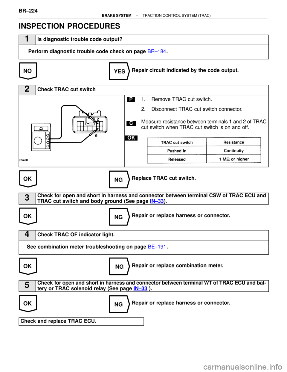
INSPECTION PROCEDURES
1Is diagnostic trouble code output?
Perform diagnostic trouble code check on page BR±184.
Repair circuit indicated by the code output.
2Check TRAC cut switch
C
OK
P1. Remove TRAC cut switch.
2. Disconnect TRAC cut switch connector.
Measure re sistance between terminals 1 and 2 of TRAC
cut switch when TRAC cut switch is on and off.
Replace TRAC cut switch.
3Check for open and short in harness and connector between terminal CSW of TRA\
C ECU and
TRAC cut switch and body ground (See page IN±33
).
Repair or replace harness or connector.
4Check TRAC OF indicator light.
See combination meter troubleshooting on page BE±191.
Repair or replace combination meter.
5Check for open and short in harness and connector between terminal WT of TRAC ECU \
and bat-
tery or TRAC solenoid relay (See page IN±33
).
Repair or replace harness or connector.
Check and replace TRAC ECU.
BR±224±
BRAKE SYSTEM TRACTION CONTROL SYSTEM (TRAC)
WhereEverybodyKnowsYourName
Page 971 of 4087
BR±150). BE±163
.
IN±33
).
WIRING DIAGRAM
TRAC Indicator Light Circuit
CIRCUIT DESCRIPTION
The TRAC indicator blinks during TRAC operation.
This indicator is also used for warnings when the trouble occurs and for disp\
laying diagnostic trouble codes.
DIAGNOSTIC CHARTDIAGNOSTIC CHART
±
BRAKE SYSTEM TRACTION CONTROL SYSTEM (TRAC)BR±225
WhereEverybodyKnowsYourName
Page 972 of 4087
BR±160).
IN±33 ).
WIRING DIAGRAM
Tc Terminal Circuit
CIRCUIT DESCRIPTION
By connecting between terminals Tc and E1 of DLC1 or DLC2, the ECU displays the diagnostic trouble
code by blinking the TRAC indicator light.
DIAGNOSTIC CHARTDIAGNOSTIC CHART
BR±226±
BRAKE SYSTEM TRACTION CONTROL SYSTEM (TRAC)
WhereEverybodyKnowsYourName
Page 973 of 4087
NGOK
OKNG
INSPECTION PROCEDURE
1Check voltage between terminals Tc and E1 of DLC 2 or DLC 1.
C
OK
PTurn ignition switch ON.
Measure voltage between terminals TC and E1 of DLC
2 or DLC 1.
Voltage: 10 ± 14 V
Proceed to next circuit inspection shown on problem
symptoms chart (See page BR±160).
2Check for open and short in harness and connector between ABS & TRAC ECU, TRAC\
ECU and
DLC 2 (or DLC 1), DLC 2 (or DLC 1) and body ground (See page IN±33).
Repair or replace harness or connector.
Check and replace TRAC ECU.
±
BRAKE SYSTEM TRACTION CONTROL SYSTEM (TRAC)BR±227
WhereEverybodyKnowsYourName