Page 1561 of 4087

POST ASSEMBLY
EG24Z±01
(See Components for Cylinder Block Prepation of
Disassembly and Post Assembly)
1. INSTALL WATER SEAL PLATE
(a) Remove any old packing (FIPG) material and be careful notto drop any oil on the contact surfaces of the seal plate and
cylinder block.
wUsing a razor blade and gasket scraper remove all the
old packing (FIPG) material from the gasket surfaces
and sealing groove.
w Thoroughly clean all components to remove all the
loose material.
w Using a non±residue solvent, clean both sealing
surfaces.
(b) Apply seal packing to the seal plate as shown in the illustration.
Seal packing:
Part No. 08826±00080 or equivalent
wInstall a nozzle that has been cut to 2 ± 3 mm (0.08±0.12
in.) opening.
w Parts must be assembled within 5 minutes of
application. Otherwise the material must be removed
and reapplied.
w Immediately remove nozzle from the tube and reinstall
cap.
(c) Install the seal plate with the 2 nuts. Alternately tighten the
nuts in several passes.
Torque: 14 N Vm (145 kgf Vcm, 10 ft Vlbf)
2. INSTALL GENERATOR BRACKET
Install the generater bracket with the bolt.
Torque: 18 N Vm (185 kgf Vcm, 13 ft Vlbf)
3. INSTALL OIL PUMP
(a) Remove any old packing (FIPG) material and be careful not
to drop any oil on the contact surfaces of the oil pump and
cylinder block.
wUsing a razor blade and gasket scraper, remove all the
old packing (FIPG) material from the gasket surfaces
and sealing groove.
w Thoroughly clean all components to remove all the
loose material.
w Using a non±residue solvent, clean both sealing
surfaces.
±
1UZ±FE ENGINE ENGINE MECHANICALEG±185
WhereEverybodyKnowsYourName
Page 1563 of 4087

4. INSTALL NO.1 AND NO.2 OIL PANS(See steps 1 to 7 on pages EG±509 to 511)
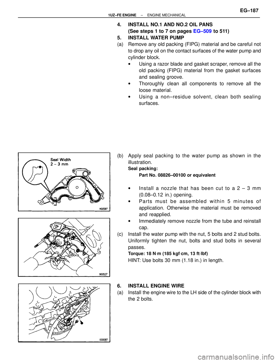
5. INSTALL WATER PUMP
(a) Remove any old packing (FIPG) material and be careful not to drop any oil on the contact surfaces of the water pump and
cylinder block.
wUsing a razor blade and gasket scraper, remove all the
old packing (FIPG) material from the gasket surfaces
and sealing groove.
w Thoroughly clean all components to remove all the
loose material.
w Using a non±residue solvent, clean both sealing
surfaces.
(b) Apply seal packing to the water pump as shown in the illustration.
Seal packing:
Part No. 08826±00100 or equivalent
wIn sta ll a no zzle th a t ha s be e n cu t to a 2 ± 3 mm
(0.08±0.12 in.) opening.
w Parts must be assembled within 5 minutes of
application. Otherwise the material must be removed
and reapplied.
w Immediately remove nozzle from the tube and reinstall
cap.
(c) Install the water pump with the nut, 5 bolts and 2 stud bolts. Uniformly tighten the nut, bolts and stud bolts in several
passes.
Torque: 18 N Vm (185 kgf Vcm, 13 ft Vlbf)
HINT: Use bolts 30 mm (1.18 in.) in length.
6. INSTALL ENGINE WIRE
(a) Install the engine wire to the LH side of the cylinder block with
the 2 bolts.
±
1UZ±FE ENGINE ENGINE MECHANICALEG±187
WhereEverybodyKnowsYourName
Page 1564 of 4087
(b) Install the engine wire cover with the 3 bolts.
(c) Connect the following connector:wCrankshaft position sensor connector
w Oil pressure switch connector
w Oil level sensor connector
7. INSTALL WATER BYPASS PIPE
(a) Install a new O±ring to the water bypass pipe.
(b) Apply soapy water to the O±ring.
(c) Push the water bypass pipe end into the pipe hole of the water pump.
(d) Install the water bypass pipe with the 2 bolts.
Torque: 18 N Vm (185 kgf Vcm, 13 ft Vlbf)
8. INSTALL KNOCK SENSORS
(a) Using SST, install the 2 knock sensors.
SST 09816±30010
Torque: 44 N Vm (450 kgf Vcm, 33 ft Vlbf)
(b) Connect the 2 knock sensor connectors.
9. INSTALL STARTER
(a) Install the engine wire clamp to the bracket on the starter.
(b) Connect the starter wire with the nut.
(c) Connect the starter connector.
(d) Install the starter with the 2 bolts.
Torque: 39 N Vm (400 kgf Vcm, 29 ft Vlbf)
EG±188±
1UZ±FE ENGINE ENGINE MECHANICAL
WhereEverybodyKnowsYourName
Page 1577 of 4087
(f) Connect the ECT sensor connector (for cooling fan).
(g) Install the ECT sensor wire clamp to the radiator fan shroud.
26. INSTALL RADIATOR RESERVOIR TANK
(a) Install the reservoir tank to the reservoir tank bracket.
(b) Install the reservoir tank with the bracket and 3 bolts.
Torque: 4.9 N.m (50 kgfVcm, 43 in. Vlbf)
(c) Connect the following hoses:
(1) Reservoir hose to water inlet housing
(2) Reservoir hose to radiator
(d) Connect the coolant level sensor connector.
27. INSTALL INTAKE AIR CONNECTOR
(a) Connect the intake air connector to the throttle body.
(b) Install the hose clamp and bolt.
(c) Connect the following hoses to the intake air connector: (1) Air hose (from IAC valve)
(2) Air hose (from air control valve on PS pump)
28. CONNECT VACUUM HOSE (A) (FROM PS AIR CONTROL VALVE) TO AIR INTAKE CHAMBER
±
1UZ±FE ENGINE ENGINE MECHANICALEG±201
WhereEverybodyKnowsYourName
Page 1588 of 4087

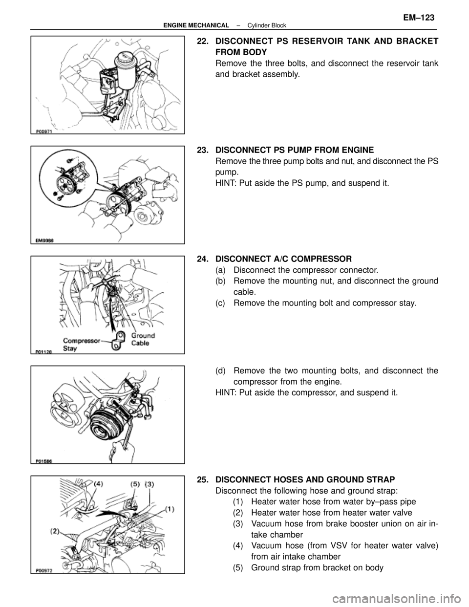
22. DISCONNECT PS RESERVOIR TANK AND BRACKET
FROM BODY
Remove the three bolts, and disconnect the reservoir tank
and bracket assembly.
23. DISCONNECT PS PUMP FROM ENGINE Remove the three pump bolts and nut, and disconnect the PS
pump.
HINT: Put aside the PS pump, and suspend it.
24. DISCONNECT A/C COMPRESSOR (a) Disconnect the compressor connector.
(b) Remove the mounting nut, and disconnect the groundcable.
(c) Remove the mounting bolt and compressor stay.
(d) Remove the two mounting bolts, and disconnect the compressor from the engine.
HINT: Put aside the compressor, and suspend it.
25. DISCONNECT HOSES AND GROUND STRAP Disconnect the following hose and ground strap:(1) Heater water hose from water by±pass pipe
(2) Heater water hose from heater water valve
(3) Vacuum hose from brake booster union on air in-
take chamber
(4) Vacuum hose (from VSV for heater water valve)
from air intake chamber
(5) Ground strap from bracket on body
±
ENGINE MECHANICAL Cylinder BlockEM±123
WhereEverybodyKnowsYourName
Page 1598 of 4087
(b) Disconnect the wire clamp from the bracket on thestarter.
(c) Remove the nut, and disconnect the wire.
(d) Disconnect the connector, and remove the starter.
8. REMOVE KNOCK SENSORS (a) Disconnect the two knock sensor connectors.
(b) Using SST, remove the two knock sensors.
SST 09816±30010
9. REMOVE WATER BY±PASS PIPE (a) Remove the two bolts.
(b) Pull out the by±pass pipe from the water pump.
(c) Remove the O±ring from the by±pass pipe.
10. REMOVE ENGINE WIRE (a) Disconnect the following connectors:(1) Oil level sensor connector
(2) Oil pressure switch connector
(b) Remove the three bolts and wire cover from the LH side
of the cylinder block.
(c) Remove the two bolts and engine wire.
±
ENGINE MECHANICAL Cylinder BlockEM±133
WhereEverybodyKnowsYourName
Page 1599 of 4087
11. REMOVE WATER PUMP(a) Remove the five mounting bolt, two mounting stud boltsand mounting nut.
(b) Remove the water pump by prying the portions between
the water pump and cylinder block with a screwdriver.
12. REMOVE NO.2 AND NO.1 OIL PANS (See steps 7 to 12 on pages LU±9 to 11)
13. REMOVE OIL PUMP (a) Remove the eight mounting bolts.
(b) Remove the oil pump by prying the portions between the
oil pump and cylinder block with a screwdriver.
(c) Remove the O±ring from the cylinder block.
14. REMOVE ALTERNATOR BRACKET Remove the bolt and bracket.
15. REMOVE WATER SEAL PLATE
Remove the two nuts and seal plate.
EM±134
±
ENGINE MECHANICAL Cylinder Block
WhereEverybodyKnowsYourName
Page 1626 of 4087

POST ASSEMBLY
(See Components on page EM±131)
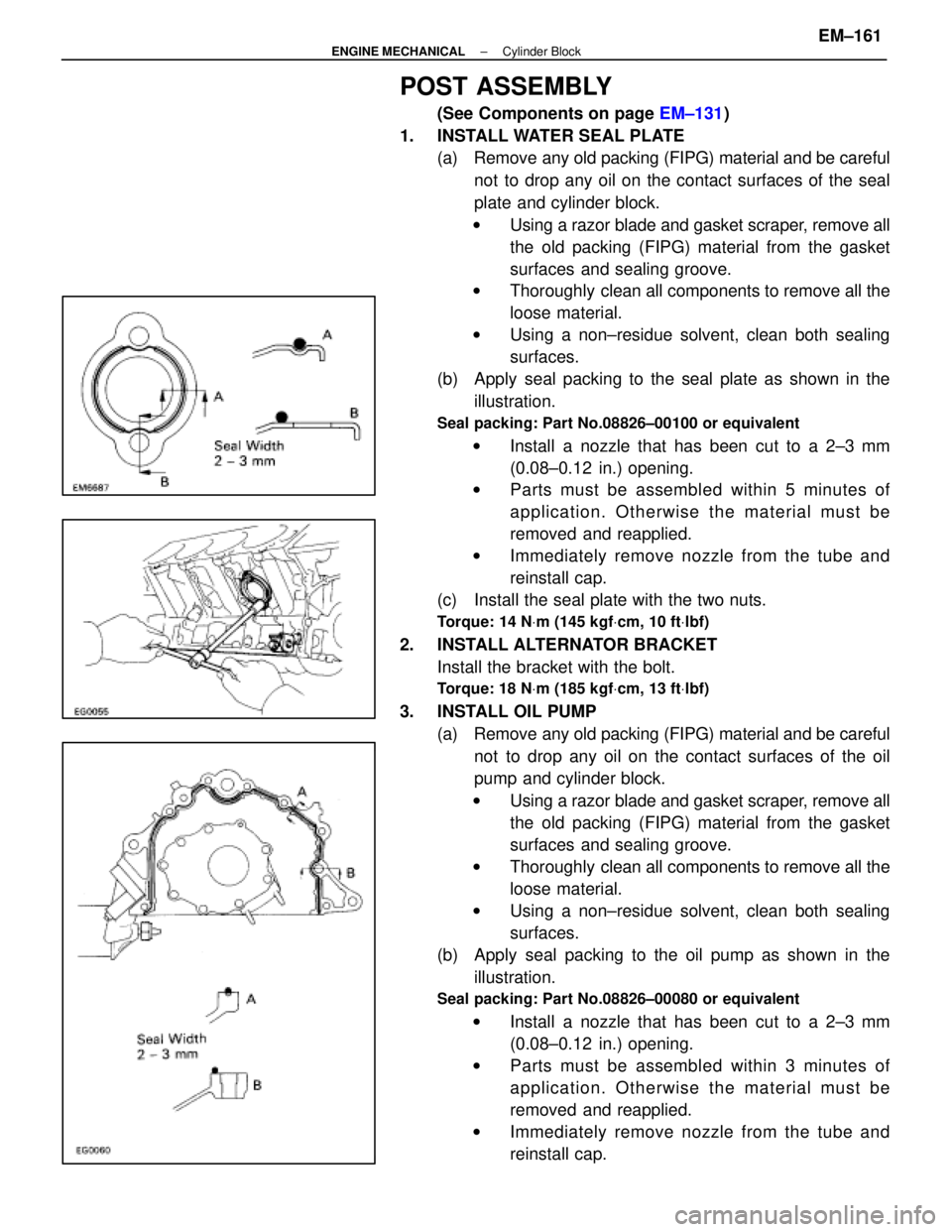
1. INSTALL WATER SEAL PLATE (a) Remove any old packing (FIPG) material and be careful
not to drop any oil on the contact surfaces of the seal
plate and cylinder block.
w Using a razor blade and gasket scraper, remove all
the old packing (FIPG) material from the gasket
surfaces and sealing groove.
w Thoroughly clean all components to remove all the
loose material.
w Using a non±residue solvent, clean both sealing
surfaces.
(b) Apply seal packing to the seal plate as shown in the
illustration.
Seal packing: Part No.08826±00100 or equivalent
w Install a nozzle that has been cut to a 2±3 mm
(0.08±0.12 in.) opening.
w Parts must be assembled within 5 minutes of
application. Otherwise the material must be
removed and reapplied.
w Immediately remove nozzle from the tube and
reinstall cap.
(c) Install the seal plate with the two nuts.
Torque: 14 N Vm (145 kgf Vcm, 10 ft Vlbf)
2. INSTALL ALTERNATOR BRACKET
Install the bracket with the bolt.
Torque: 18 N Vm (185 kgf Vcm, 13 ft Vlbf)
3. INSTALL OIL PUMP
(a) Remove any old packing (FIPG) material and be carefulnot to drop any oil on the contact surfaces of the oil
pump and cylinder block.
w Using a razor blade and gasket scraper, remove all
the old packing (FIPG) material from the gasket
surfaces and sealing groove.
w Thoroughly clean all components to remove all the
loose material.
w Using a non±residue solvent, clean both sealing
surfaces.
(b) Apply seal packing to the oil pump as shown in the
illustration.
Seal packing: Part No.08826±00080 or equivalent
w Install a nozzle that has been cut to a 2±3 mm
(0.08±0.12 in.) opening.
w Parts must be assembled within 3 minutes of
application. Otherwise the material must be
removed and reapplied.
w Immediately remove nozzle from the tube and
reinstall cap.
±
ENGINE MECHANICAL Cylinder BlockEM±161
WhereEverybodyKnowsYourName