Page 2897 of 4087
6. REMOVE UPPER HIGH±TENSION CORD COVER(a) Remove the two mounting bolts.
(b) Disconnect the front side claw groove of the cord coverfrom the claw of the lower cover, and remove the cord
cover.
7. REMOVE RH ENGINE WIRE COVER Remove the bolt and engine wire cover.
8. REMOVE LH ENGINE WIRE COVER Remove the two bolts and engine wire cover.
9. REMOVE VSV FOR EVAP SYSTEM Remove the two bolts, and disconnect the VSV from cylinder
head and timing belt cover.
10. REMOVE RH NO.3 TIMING BELT COVER Remove the three bolts and timing belt cover.
±
STARTING SYSTEM StarterST±7
WhereEverybodyKnowsYourName
Page 2898 of 4087
11. REMOVE LH NO.3 TIMING BELT COVER(a) Remove the four mounting bolts.
(b) Disconnect the cord grommet from the timing belt cover,
and remove the timing belt cover.
(c) Remove the cord grommet from the high±tension cord.
12. REMOVE LOWER HIGH±TENSION CORD COVER (a) Disconnect the high±tension cord from the RH ignitioncoil.
(b) D i s c onnect the high±tension cords from the
high±tension cord cover.
(c) Remove the bolt and cord cover.
13. REMOVE THROTTLE BODY (a) Disconnect the following connectors:(1) Throttle position sensor connector
(2) (w/ TRAC)
Sub±throttle position sensor connector
(3) (w/ TRAC) Sub±throttle actuator connector
(b) Disconnect the following hoses: (1) Heat water hose from heater water valve
ST±8
±
STARTING SYSTEM Starter
WhereEverybodyKnowsYourName
Page 2922 of 4087
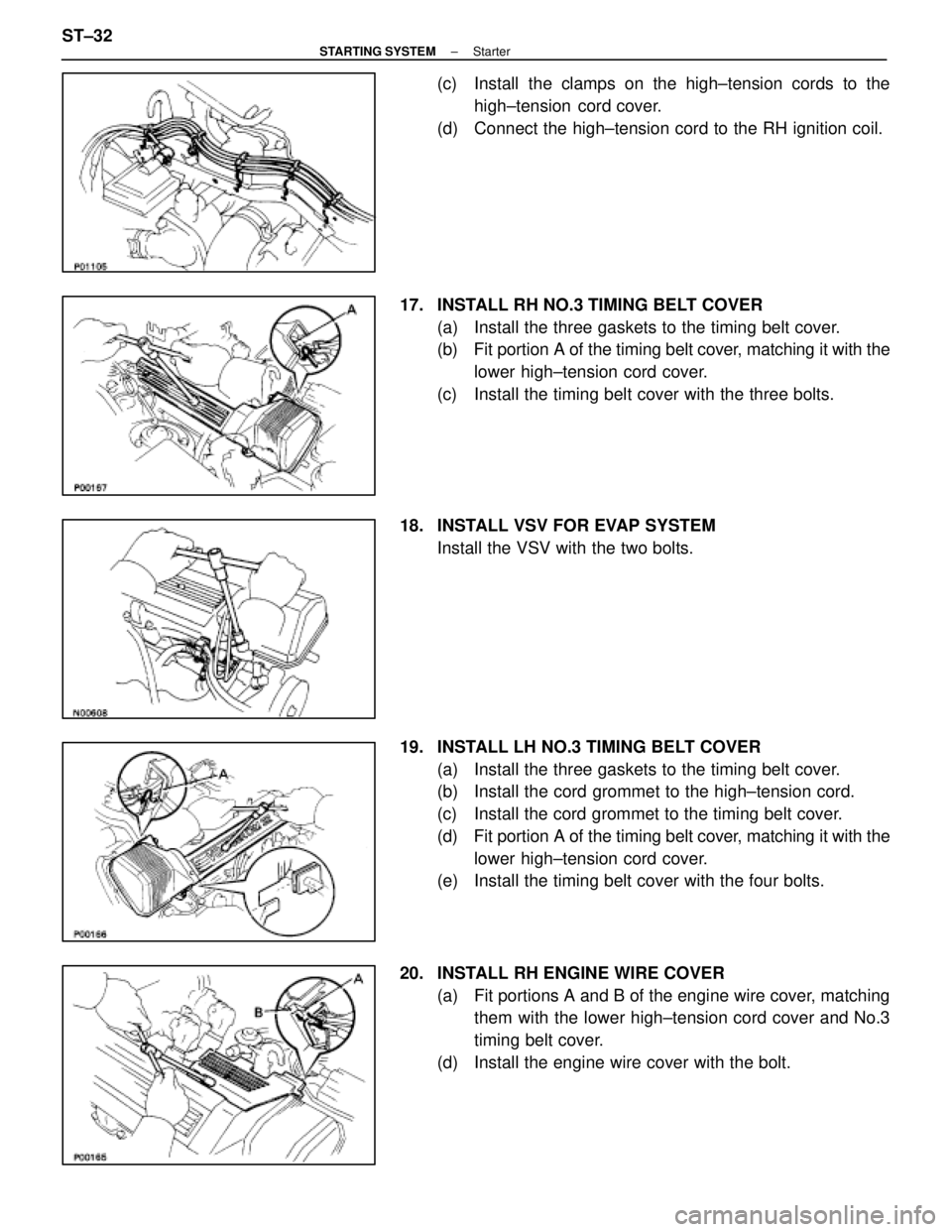
(c) Install the clamps on the high±tension cords to thehigh±tension cord cover.
(d) Connect the high±tension cord to the RH ignition coil.
17. INSTALL RH NO.3 TIMING BELT COVER (a) Install the three gaskets to the timing belt cover.
(b) Fit portion A of the timing belt cover, matching it with the
lower high±tension cord cover.
(c) Install the timing belt cover with the three bolts.
18. INSTALL VSV FOR EVAP SYSTEM Install the VSV with the two bolts.
19. INSTALL LH NO.3 TIMING BELT COVER (a) Install the three gaskets to the timing belt cover.
(b) Install the cord grommet to the high±tension cord.
(c) Install the cord grommet to the timing belt cover.
(d) Fit portion A of the timing belt cover, matching it with the
lower high±tension cord cover.
(e) Install the timing belt cover with the four bolts.
20. INSTALL RH ENGINE WIRE COVER (a) Fit portions A and B of the engine wire cover, matchingthem with the lower high±tension cord cover and No.3
timing belt cover.
(d) Install the engine wire cover with the bolt.
ST±32
±
STARTING SYSTEM Starter
WhereEverybodyKnowsYourName
Page 2923 of 4087
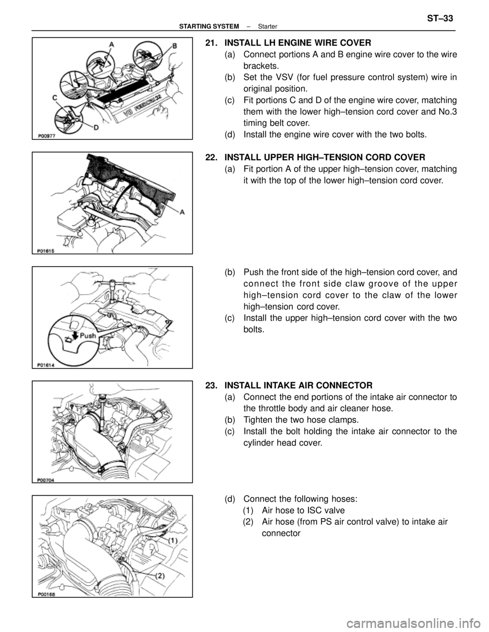
21. INSTALL LH ENGINE WIRE COVER(a) Connect portions A and B engine wire cover to the wirebrackets.
(b) Set the VSV (for fuel pressure control system) wire in
original position.
(c) Fit portions C and D of the engine wire cover, matching them with the lower high±tension cord cover and No.3
timing belt cover.
(d) Install the engine wire cover with the two bolts.
22. INSTALL UPPER HIGH±TENSION CORD COVER (a) Fit portion A of the upper high±tension cover, matchingit with the top of the lower high±tension cord cover.
(b) Push the front side of the high±tension cord cover, and connect the front side claw groove of the upper
high±tension cord cover to the claw of the lower
high±tension cord cover.
(c) Install the upper high±tension cord cover with the two
bolts.
23. INSTALL INTAKE AIR CONNECTOR (a) Connect the end portions of the intake air connector tothe throttle body and air cleaner hose.
(b) Tighten the two hose clamps.
(c) Install the bolt holding the intake air connector to the cylinder head cover.
(d) Connect the following hoses: (1) Air hose to ISC valve
(2) Air hose (from PS air control valve) to intake air connector
±
STARTING SYSTEM StarterST±33
WhereEverybodyKnowsYourName
Page 3388 of 4087
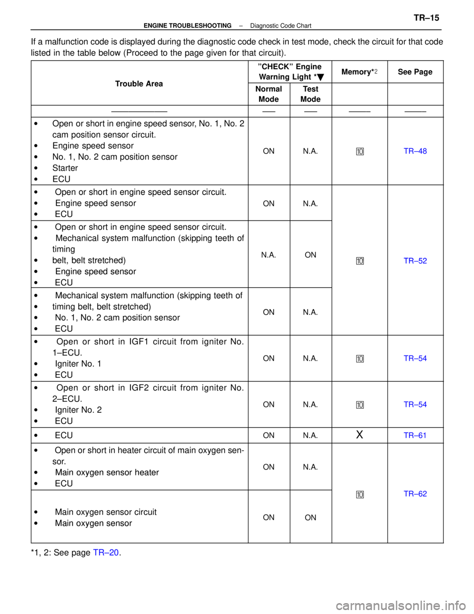
If a malfunction code is displayed during the diagnostic code check in tes\
t mode, check the circuit for that code
listed in the table below (Proceed to the page given for that circuit).
Tro ble Area
ºCHECKº EngineWarning Light * �Memory*�See Page
Trouble AreaNormal
ModeTest
Mode
±±±±±±±±±±±±±±±±±±±±±±±±±±±±±
w Open or short in engine speed sensor, No. 1, No. 2
cam position sensor circuit.
w Engine speed sensor
w No. 1, No. 2 cam position sensor
w Starter
w ECU
ONN.A.�TR±48
w Open or short in engine speed sensor circuit.w Oen or short in engine s eed sensor circuit.
w Engine speed sensor
ONN.A. Engine s eed sensor
w ECU
ONN.A.
w Open or short in engine speed sensor circuit.g
w Mechanical system malfunction (skipping teeth of
ti itiming
wbelt belt stretched)N.A.ON�TR 52wbelt, belt stretched)
wEngine speed sensor
�TR±52
w Engine s eed sensor
w ECU
w Mechanical system malfunction (skipping teeth ofw Mechanical system malfunction (ski ing teeth of
wtiming belt, belt stretched)ONNAwtiming belt, belt stretched)
w No. 1, No. 2 cam position sensorONN.A. No. 1, No. 2 cam osition sensor
w ECU
w Open or short in IGF1 circuit from igniter No.
1±ECU.
w Igniter No. 1
w ECU
ONN.A.�TR±54
w Open or short in IGF2 circuit from igniter No.
2±ECU.
w Igniter No. 2
w ECU
ONN.A.�TR±54
w ECUONN.A.XTR±61
w Open or short in heater circuit of main oxygen sen-
sor.
w Main oxygen sensor heaterONN.A.w Main oxygen sensor heater
w ECU
�TR±62
w Main oxygen sensor circuit
w
Main oxygen sensorONONw Main oxygen sensor
*1, 2: See page TR±20.
±
ENGINE TROUBLESHOOTING Diagnostic Code ChartTR±15
WhereEverybodyKnowsYourName
Page 3390 of 4087
ºCHECKº Engine
Tro ble Area
CHECK Engine
Warning Light *�Memory*�See PageTrouble AreaNormal
ModeTest
ModeMemory* �See Page
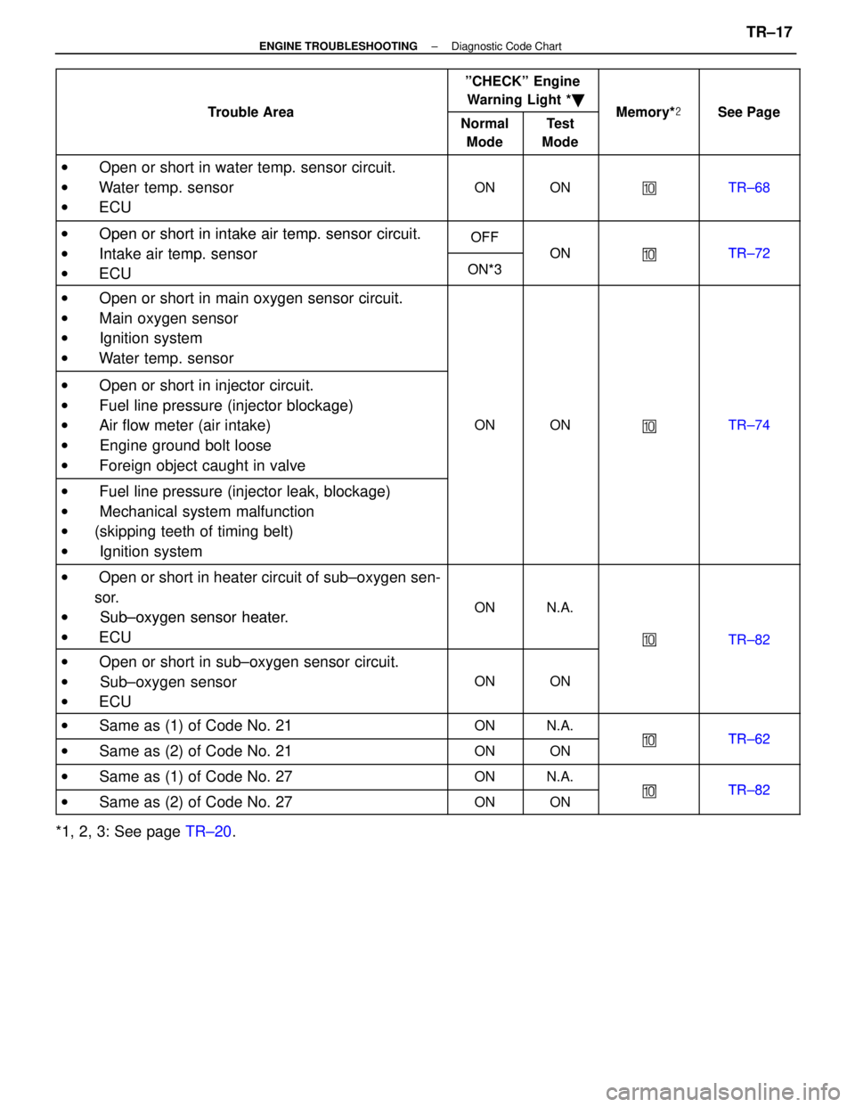
w Open or short in water temp. sensor circuit.
w Water temp. sensor
w ECU
ONON�TR±68
w Open or short in intake air tempsensor circuitOFFw Open or short in intake air temp. sensor circuit.
w Intake air tempsensor
OFF
ON�TR 72w Intake air temp. sensor
ECUON*3
ON�TR±72
w ECUON*3
w Open or short in main oxygen sensor circuit.w Oen or short in main oxygen sensor circuit.
w Main oxygen sensor
Main oxygen sensor
w Ignition systemgy
w Water temp. sensor
w Open or short in injector circuit.w Oen or short in injector circuit.
w Fuel line pressure
(injector blockage)w Fuel line ressure (injector blockage)
w Air flow meter (air intake)ONON�TR±74 Air flow meter (air intake)
w Engine ground bolt loose
�
gg
w Foreign object caught in valve
w Fuel line pressure (injector leak, blockage)w Fuel line ressure (injector leak, blockage)
w Mechanical system malfunction Mechanical system malfunction
w(skipping teeth of timing belt)(g g)
w Ignition system
w Open or short in heater circuit of sub±oxygen sen-
sor.
w Sub±oxygen sensor heaterONN.A.w Sub±oxygen sensor heater.
w ECU
�TR±82
w Open or short in sub±oxygen sensor circuit.
�TR 82
w Oen or short in sub oxygen sensor circuit.
w Sub±oxygen sensor
ONON Sub oxygen sensor
w ECU
w Same as (1) of Code No. 21ONN.A.
�TR 62w Same as (2) of Code No. 21ONON�TR±62
w Same as (1) of Code No. 27ONN.A.
�TR 82w Same as (2) of Code No. 27ONON�TR±82
*1, 2, 3: See page TR±20.
±
ENGINE TROUBLESHOOTING Diagnostic Code ChartTR±17
WhereEverybodyKnowsYourName
Page 3446 of 4087
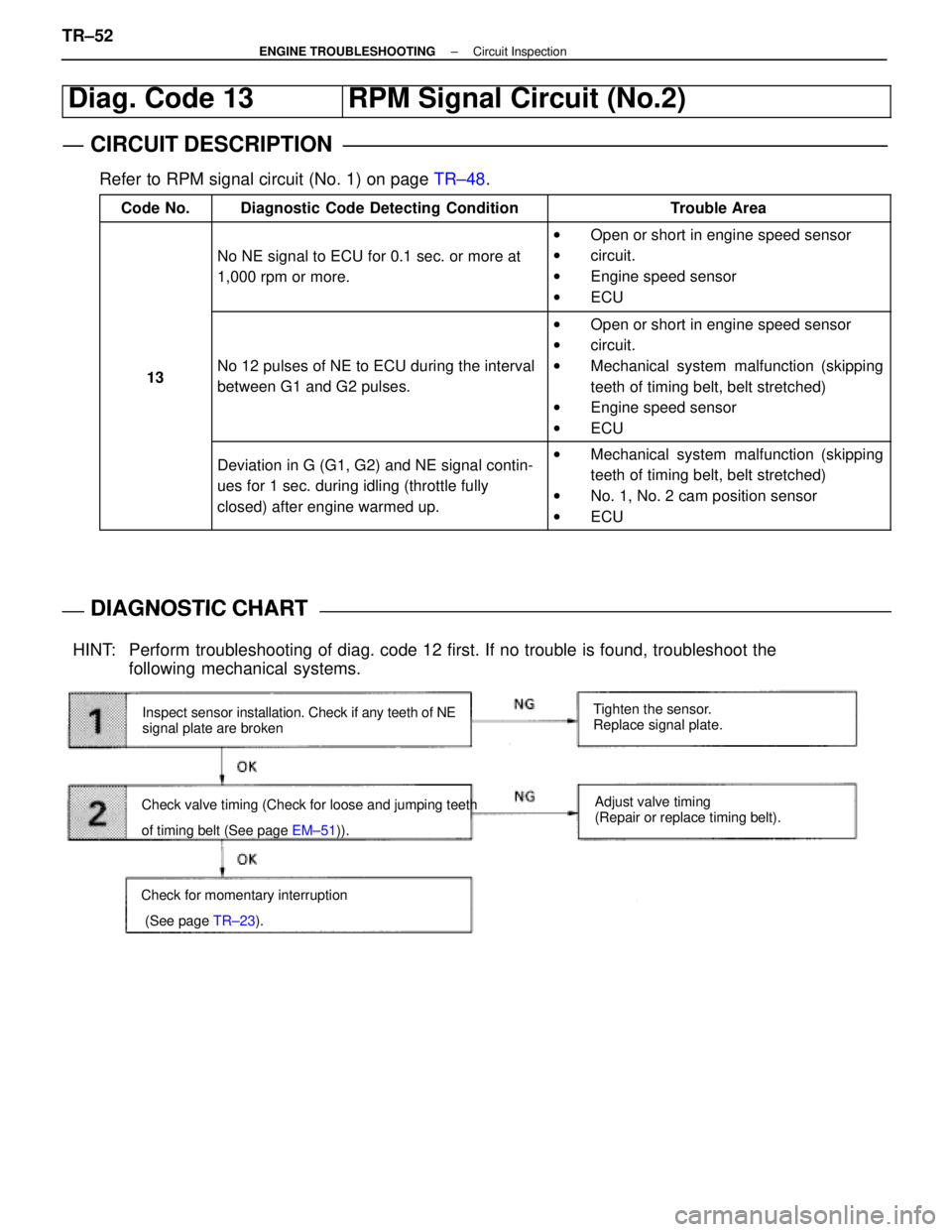
Diag. Code 13RPM Signal Circuit (No.2)
CIRCUIT DESCRIPTION
Refer to RPM signal circuit (No. 1) on page TR±48.
Code No.Diagnostic Code Detecting ConditionTrouble Area
No NE signal to ECU for 0.1 sec. or more at
1,000 rpm or more.
wOpen or short in engine speed sensor
w circuit.
w Engine speed sensor
w ECU
13No 12 pulses of NE to ECU during the interval
between G1 and G2 pulses.
wOpen or short in engine speed sensor
w circuit.
w Mechanical system malfunction (skipping
teeth of timing belt, belt stretched)
w Engine speed sensor
w ECU
Deviation in G (G1, G2) and NE signal contin-
ues for 1 sec. during idling (throttle fully
closed) after engine warmed up.wMechanical system malfunction (skipping
teeth of timing belt, belt stretched)
w No. 1, No. 2 cam position sensor
w ECU
DIAGNOSTIC CHARTDIAGNOSTIC CHART
Inspect sensor installation. Check if any teeth of NE
signal plate are broken
Check valve timing (Check for loose and jumping teeth
of timing belt (See page EM±51)). Tighten the sensor.
Replace signal plate.
Adjust valve timing
(Repair or replace timing belt).
HINT: Perform troubleshooting of diag. code 12 first. If no trouble is found, trouble\
shoot the following mechanical systems.
Check for momentary interruption
(See page TR±23).
TR±52±
ENGINE TROUBLESHOOTING Circuit Inspection
WhereEverybodyKnowsYourName
Page 3474 of 4087

Diag Code 25 26
Air±Fuel Ratio Lean Malfunction
Diag. Code 25, 26
Air±Fuel Ratio Rich Malfunction
CIRCUIT DESCRIPTION
Refer to page TR±62 for the circuit description.
Code No.
Diagnostic Code Detecting SystemTrouble Area
(1) Main oxygen sensor voltage is 0.45 V or less (lean) for 90 sec. under conditions
(a) and (b).
(2 trip detection logic)
*2
(a) Coolant temp.: 70 °C (158 °F)
or more.
(b) Engine speed: 1,500 rpm or more.
� Open or short in main oxygen sensor
circuit
� Main oxygen sensor
� Ignition system
� ECU
25
(2)*1 Difference of air±fuel ratio feedback
compensation value between front (No.
1 3 cylinders) and rear (No. 4 6
cylinders) is more than 15 percentage
for 20 sec. or more under conditions (a)
and (b).
(2 trip detection logic)
*2
(a) Engine speed: 2,000 rpm or more.
(b) Coolant temp.: Between 60 °C
(140 °F) and 95 °C (203 °F).
� Open and short in injector circuit.
� Fuel line pressure (injector leak, blockage)
� Mechanical system malfunction (skipping
teeth of timing belt)
� Ignition system
� Compression pressure (foreign object
caught in valve)
� Air flow meter (air intake)
� ECU
(3)*1 Engine speed varies by more than 15
rpm over the preceding crank angle period
during a period of 20 sec. or more under
conditions (a) and (b).
(2 trip detection logic)
*2
(a) Engine speed: Idling
(b) Coolant temp.: Between 60 °C
(140 °F) and 95 °C (203 °F).
� Open and short in injector circuit.
� Fuel line pressure (injector leak, blockage)
� Mechanical system malfunction (skipping
teeth of timing belt)
� Ignition system
� Compression pressure (foreign object
caught in valve)
� Air flow meter (air intake)
� ECU
26*1
(1) Difference of air±fuel ratio feedback
compensation value between front (No. 1
3 cylinders) and rear (No.4 6 cylinders) is
more than 15 percentage for 20 sec. or
more under conditions (a) and (b).
(2 trip detection logic)
*2
(a) Engine speed: 2,000 rpm or more.
(b) Coolant temp.: Between 60 °C
(140 °F) and 95 °C (203 °F).
� Open and short in injector circuit.
� Fuel line pressure (injector leak, blockage)
� Mechanical system malfunction (skipping
teeth of timing belt)
� Ignition system
� Compression pressure (foreign object
caught in valve)
� Air flow meter (air intake)
� ECU
261
(2) Engine speed varies by more than 15
rpm over the preceding crank angle peri-
od during a period of 20 sec. or more un-
der conditions (a) and (b).
(2 trip detection logic)
*2
(a) Engine speed: Idling
(b) Coolant temp.: Between 60 °C
(140 °F) and 95 °C (203 °F).
� Open and short in injector circuit.
� Fuel line pressure (injector leak, blockage)
� Mechanical system malfunction (skipping
teeth of timing belt)
� Ignition system
� Compression pressure (foreign object
caught in valve
� Air flow meter (air intake)
� ECU
*1: Only for USA specification vehicles.
*2: See page TR±25.
TR±70
±
ENGINE TROUBLESHOOTING Circuit Inspection
WhereEverybodyKnowsYourName