Page 804 of 4087
PREPARATION
SST (SPECIAL SERVICE TOOLS)
IllustrationPart No.Part NameNote
09213±31021
Crankshaft Pulley
Puller
For removing steering wheel
RECOMMENDED TOOLS
IllustrationPart No.Part NameNote
09082±00015TOYOTA
Electrical Tester
09041±0030Torx Driver
T30
For removing and installing steering wheel pad and
power window motor
09042±00010Torx Socket
T30For removing and installing steering wheel pad and
power window motor
EQUIPMENT
Part NameNote
Voltmeter
Ammeter
Ohmmeter
Test lead
ThermometerWater temperature sender gauge, Engine oil level, Warning switch, Seat heater
SyphonBrake fluid level warning switch
Oil bathEngine oil level warning switch
Bulb (1.4 W)Coolant level warning ECU
Bulb (3.4 W)Fuel sender, gauge, Seat belt warning relay
Bulb (21 W)Turn signal flasher relay
Dry cell batteryFuel sender gauge
Heat lightSeat heater
Hexagon wrench (6 mm)Power seat
BE±8±
BODY ELECTRICAL SYSTEM Preparation
WhereEverybodyKnowsYourName
Page 852 of 4087

Description ± Taillight System
The component parts of this system and their function are as shown in the f\
ollowing table.
�������� ��������Parts Name������������������\
��������")
(TAILLIGHT SYSTEM)
Description ± Taillight System
The component parts of this system and their function are as shown in the f\
ollowing table.
�������� ��������Parts Name������������������\
����������� ������������������\
�����������Function
�������� �
�������
��������
Light Control Switch������������������\
����������� �
������������������\
����������
������������������\
�����������
Grounds current from the taillight control relay via the integration rel\
ay, switching each relay
and supplying current to the appropriate bulbs accordance with the switc\
h position.
�������� ��������Taillight Control Relay������������������\
����������� ������������������\
�����������Turned on by signals from the light control switch and supplies current t\
o each bulb.
�������� �
�������
�
�������
��������
Integration Relay
������������������\
����������� �
������������������\
����������
�
������������������\
����������
������������������\
�����������
Carries out ºLight Auto Turn±Offº of the headlights, fog lights and taillights and cuts off cur-
rent to the light control switch in accordance with signals from the GAU\
GE fuse and door
courtesy switch.
�������� �
�������
��������
Light Failure Sensor������������������\
����������� �
������������������\
����������
������������������\
�����������
This sensor senses when a bulb in rear combination light is burnt out an\
d lights up a warning
light.
��������Integration Relay������������������\
������������������� ��������Integration Relay
(Daytime Running
������������������\
����������� ������������������\
�����������
Refer to
BE±30.�������� ��������(y g
Light Relay: CANADA)������������������\
����������� ������������������\
�����������
PARTS LOCATION ± Taillight System
±
BODY ELECTRICAL SYSTEM Lighting SystemBE±53
WhereEverybodyKnowsYourName
Page 858 of 4087
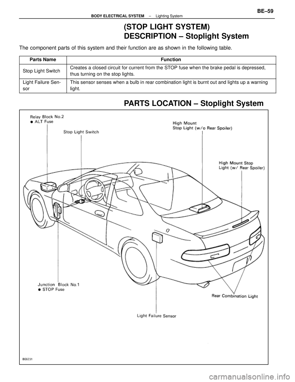
(STOP LIGHT SYSTEM)
DESCRIPTION ± Stoplight System
The component parts of this system and their function are as shown in the f\
ollowing table.
������� �������Parts Name������������������\
������������ ������������������\
������������Function
������� �
������
�������Stop Light Switch
������������������\
������������ �
������������������\
�����������
������������������\
������������
Creates a closed circuit for current from the STOP fuse when the brake pedal is depressed,
thus turning on the stop lights.
������� �
������
�������
Light Failure Sen-
sor������������������\
������������ �
������������������\
�����������
������������������\
������������
This sensor senses when a bulb in rear combination light is burnt out an\
d lights up a warning
light.
PARTS LOCATION ± Stoplight System
±
BODY ELECTRICAL SYSTEM Lighting SystemBE±59
WhereEverybodyKnowsYourName
Page 864 of 4087
(TURN SIGNAL AND HAZARD WARNING
LIGHT SYSTEM)
Description ± TURN SIGNAL AND
HAZARD WARNING LIGHT SYSTEM
The component parts of this system and their function are as shown in the f\
ollowing table.
Parts NameFunction
Turn Signal SwitchSwitches current from the turn signal flasher to the left side or right \
side.
Hazard Warning
SwitchModifies the circuit to the flasher relay and turn signal switch in acco\
rdance with the
respective switch positions.
Turn Signal FlasherReceives current from the hazard warning switch and flashes the turn sig\
nal lights by
switching the current to the lights ON and OFF.
PARTS LOCATION ± TURN SIGNAL
±
BODY ELECTRICAL SYSTEM Lighting SystemBE±65
WhereEverybodyKnowsYourName
Page 865 of 4087
WIRING AND CONNECTOR DIAGRAMS
Turn Signal and Hazard Warning Lights
BE±66±
BODY ELECTRICAL SYSTEM Lighting System
WhereEverybodyKnowsYourName
Page 867 of 4087

(Combination Switch Assembly)
(See page BE±39)
HINT: Inspect turn signal light switch.
(Turn Signal Flasher)
REMOVAL AND INSTALLATION OF TURN
SIGNAL FLASHER
(S")
Parts Inspection (Turn and Hazard)
(Combination Switch Assembly)
(See page BE±39)
HINT: Inspect turn signal light switch.
(Turn Signal Flasher)
REMOVAL AND INSTALLATION OF TURN
SIGNAL FLASHER
(See page BE±16 )
INSPECTION OF TURN SIGNAL
FLASHER
INSPECT TURN SIGNAL FLASHER
(Operation)
LHD Side
(a) Connect the positive (+) lead from the battery to terminal
1 and the negative (±) lead to 4.
(b) Connect the two turn signal light bulbs parallel to each other to terminals 3 and 4, check that bulbs flash.
RHD Side
(c) Connect the positive (+) lead from the battery to terminal
1 and the negative (±) lead to 2.
(d) Connect two turn signal light bulbs parallel to each other
to terminals 2 and 5, check that the bulbs flash.
HINT: The turn signal lights should flash 60 to 120 times per
minute.
If one of the front or rear turn signal lights has an open circuit,
the number of flashes will be more than 140 per minute.
If operation is not as specified, replace the flasher.
(Flasher Circuit)
(See page BE±23 )
(HAZARD WARNING SWITCH)
REMOVAL AND INSTALLATION OF
HAZARD WARNING SWITCH
1. REMOVE INSTRUMENT PANEL NO.2 REGISTER
ASSEMBLY
(See page BO±111 )
2. REMOVE HAZARD WARNING SWITCH Remove two screws and hazard warning switch from register.
3. INSTALL HAZARD WARNING SWITCH AND REGISTER
For installation, follow the removal procedure in reverse.
BE±68
±
BODY ELECTRICAL SYSTEM Lighting System
WhereEverybodyKnowsYourName
Page 895 of 4087

DESCRIPTION
The combination meter has various meters and gauges which show the vehicle'\
s condition, warning lights which
monitor abnormalities in the vehicle and inform the driver, indicator lights which inform the driver of the condition
of each part of vehicle, and a function for illumination and brightness ad\
justment of meters and gauges.
The component parts of this system and their functions are described in \
the following table.
Parts NameFunction
SpeedometerThe speedometer needle moves in accordance with signals from the speed s\
ensor to
indicate the vehicle's speed.
TachometerThe tachometer needle moves in accordance with signals from the igniter \
to indicate the
engine's speed.
Water Temperatrue
GaugeThe water temperature gauge's needle moves in accordance with signals from the send-
er gauge and indicates the temperature of the engine coolant.
Fuel GaugeThe fuel gauge needle moves in accordance with signals from the sender g\
auge, indicat-
ing the amount of fuel remaining in the fuel tank.
OdometerThe odometer counts the total distance traveled by the vehicle in accord\
ance with pulse
signals from the speed sensor.
Twin Trip Switch
The twin trip meter counts the distance traveled by the vehicle in accor\
dance with pulse
signals from the speed sensor. It can be reset using a switch and can be used to switch
between trip meters A and B.
Circuit Plate
This plate contains the circuitry for each meter and gauge and for each \
warning light and
indicator light, as well as an internal engine oil level warning drive c\
ircuit, drive circuits for
the odometer and trip meter and brightness adjustment circuitry for each\
indicator.
Speed SensorMounted in the transmission, this sensor outputs pulse signals to the co\
mbination meter
in accordance with the speed of the output shaft.
Twin Trip SwitchOperation of this switch switches between the A and B trip meters and se\
nds reset sig-
nals to the combination meter.
Water
Temperature Sender
GaugeThis sender converts engine coolant temperatures to a resistance value i\
n signal form to
the combination meter.
Fuel Sender GaugeThis sender converts the level of fuel remaining in fuel tank to resista\
nce value and
sends the resistance value in signal form to combination meter.
Rheostat Light
Control VolumeIn order to adjust the degree of illumination of the combination meter, the resistance val-
ue of the built±in variable resistor is sent to the combination meter\
and rheostat light
control.
Fuel Level Warning
SwitchWhen the level of fuel remaining falls below a predetermined level, cont\
inuity is estab-
lished with this switch, which is built into the fuel sender gauge, caus\
ing a warning light
to light up.
Low Oil Pressure
Warning SwitchThis switch is mounted on the engine block. Continuity is established in\
this switch when
the oil pressure is low, causing a warning light to light up.
Integration Relay (Seat
Belt Warning Relay)
This relay receives current from fuse GAUGE and DOME and is connected to\
each
buckle switch, door courtesy switch, key unlock warning switch and warni\
ng light. As
part of the seat belt warning system, it sounds a chime and lights a war\
ning light when
seat belts are unfastened. As part of the key unlock warning system, it \
sounds a chime
when the set conditions are fulfilled.
Light Failure SensorThis sensor senses when a bulb in rear combination light is burnt out an\
d lights up a
warning light.
BE±96±
BODY ELECTRICAL SYSTEM Combination Meter
WhereEverybodyKnowsYourName
Page 896 of 4087

Parts NameFunction
Coolant Level
Warning SwitchThis switch is installed in the radiator reservoir tank. It lights up a \
warning light when the
coolant level becomes low.
Engine Oil Level
Warning SwitchThis switch is mounted in the engine oil pan. It lights a warning light \
when the engine oil
level is low.
Brake Fluid Level
Warning SwitchThis switch is mounted in the brake master cylinder reservoir tank. It l\
ights up a warning
light when the brake fluid level is low.
Parking Brake SwitchThis switch is on the parking brake lever bracket. Continuity in this sw\
itch is established
when the lever is released, causing a warning light to light up.
Door Courtesy SwitchContinuity is established in this switch when a door is opened, causing \
a warning light to
light up.
Warning LightsWhen an abnormality is detected in the vehicle, current is sent to these\
lights, or they are
grounded, causing them to light up.
Indicator LightsCurrent is sent to these lights, or they are grounded, causing them to l\
ight up and indicate
the vehicle's condition to the driver.
Window Washer Level
Warning SwitchThis switch is mounted in the window washer tank. It lights a warning li\
ght when the
window washer level becomes low.
±
BODY ELECTRICAL SYSTEM Cominbation MeterBE±97
WhereEverybodyKnowsYourName

IllustrationPart No.Part NameNote
09213±31021
Crankshaft Pulley
Puller
For removing steering wheel
RECOMMENDED TOOLS
IllustrationPart No.Part NameNote
09082±")

Description ± TURN SIGNAL AND
HAZARD WARNING LIGHT SYSTEM
The component parts of this system and their function are as shown in the f\
ollowing table.
P")
