1991 FORD FESTIVA water pump
[x] Cancel search: water pumpPage 116 of 454
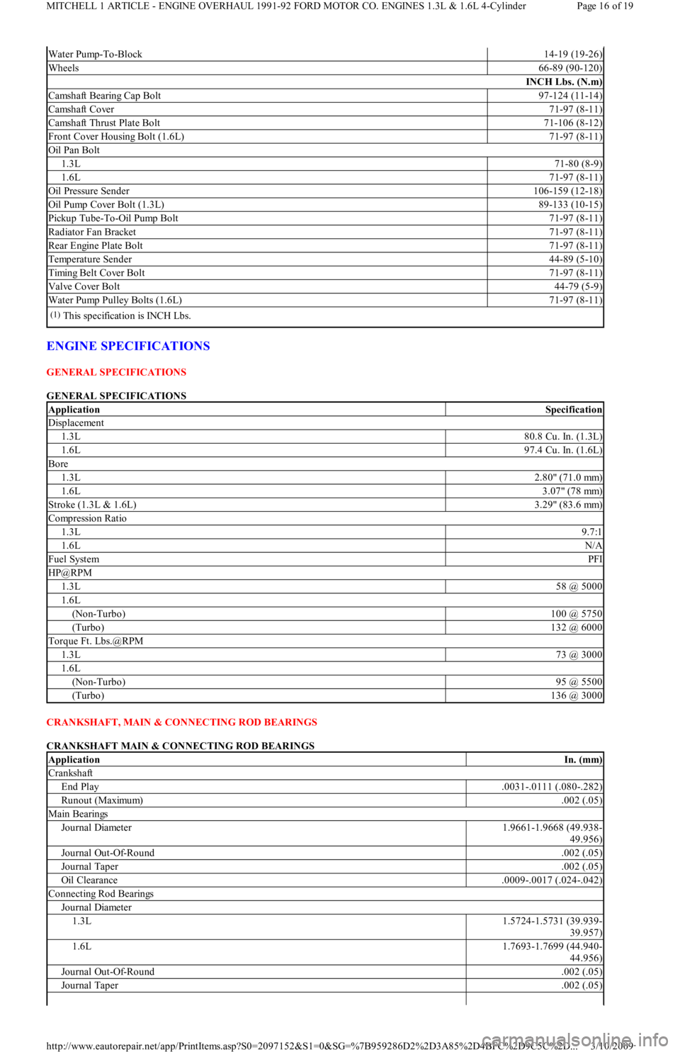
ENGINE SPECIFICATIONS
GENERAL SPECIFICATIONS
GENERAL SPECIFICATIONS
CRANKSHAFT, MAIN & CONNECTING ROD BEARINGS
CRANKSHAFT MAIN & CONNECTING ROD BEARINGS
Water Pump-To-Block14-19 (19-26)
Wheels66-89 (90-120)
INCH Lbs. (N.m)
Camshaft Bearing Cap Bolt97-124 (11-14)
Camshaft Cover71-97 (8-11)
Camshaft Thrust Plate Bolt71-106 (8-12)
Front Cover Housing Bolt (1.6L)71-97 (8-11)
Oil Pan Bolt
1.3L71-80 (8-9)
1.6L71-97 (8-11)
Oil Pressure Sender106-159 (12-18)
Oil Pump Cover Bolt (1.3L)89-133 (10-15)
Pickup Tube-To-Oil Pump Bolt71-97 (8-11)
Radiator Fan Bracket71-97 (8-11)
Rear Engine Plate Bolt71-97 (8-11)
Temperature Sender44-89 (5-10)
Timing Belt Cover Bolt71-97 (8-11)
Valve Cover Bolt44-79 (5-9)
Water Pump Pulley Bolts (1.6L)71-97 (8-11)
(1)This specification is INCH Lbs.
ApplicationSpecification
Displacement
1.3L80.8 Cu. In. (1.3L)
1.6L97.4 Cu. In. (1.6L)
Bore
1.3L2.80" (71.0 mm)
1.6L3.07" (78 mm)
Stroke (1.3L & 1.6L)3.29" (83.6 mm)
Compression Ratio
1.3L9.7:1
1.6LN/A
Fuel SystemPFI
HP@RPM
1.3L58 @ 5000
1.6L
(Non-Turbo)100 @ 5750
(Turbo)132 @ 6000
Torque Ft. Lbs.@RPM
1.3L73 @ 3000
1.6L
(Non-Turbo)95 @ 5500
(Turbo)136 @ 3000
ApplicationIn. (mm)
Crankshaft
End Play.0031-.0111 (.080-.282)
Runout (Maximum).002 (.05)
Main Bearings
Journal Diameter1.9661-1.9668 (49.938-
49.956)
Journal Out-Of-Round.002 (.05)
Journal Taper.002 (.05)
Oil Clearance.0009-.0017 (.024-.042)
Connecting Rod Bearings
Journal Diameter
1.3L1.5724-1.5731 (39.939-
39.957)
1.6L1.7693-1.7699 (44.940-
44.956)
Journal Out-Of-Round.002 (.05)
Journal Taper.002 (.05)
Page 16 of 19 MITCHELL 1 ARTICLE - ENGINE OVERHAUL 1991-92 FORD MOTOR CO. ENGINES 1.3L & 1.6L 4-Cylinder
3/10/2009 http://www.eautorepair.net/app/PrintItems.asp?S0=2097152&S1=0&SG=%7B959286D2%2D3A85%2D4BFC%2D9C5C%2D
...
Page 126 of 454
Back To Article
FORD
1.3L 4-Cylinder
MANUFACTURER'S SUGGESTED SCHEDULED MAINTENANCE
For Aspire, the manufacturer recommends the belt be replaced every 60,000 miles on Federal vehicles, and 105,000 miles on California
vehicles. For Festiva, the manufacturer recommends the belt be replaced every 60,000 miles.
REMOVAL & INSTALLATION
TIMING BELT
Removal
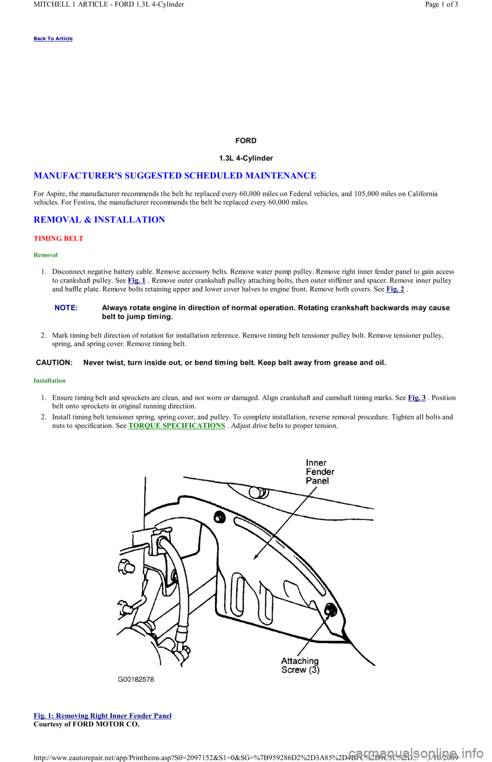
1. Disconnect negative battery cable. Remove accessory belts. Remove water pump pulley. Remove right inner fender panel to gain access
to crankshaft pulley. See Fig. 1
. Remove outer crankshaft pulley attaching bolts, then outer stiffener and spacer. Remove inner pulley
and baffle plate. Remove bolts retaining upper and lower cover halves to engine front. Remove both covers. See Fig. 2
.
2. Mark timing belt direction of rotation for installation reference. Remove timing belt tensioner pulley bolt. Remove tensioner pulley,
spring, and spring cover. Remove timing belt.
Installation
1. Ensure timing belt and sprockets are clean, and not worn or damaged. Align crankshaft and camshaft timing marks. See Fig. 3 . Position
belt onto sprockets in original running direction.
2. Install timing belt tensioner spring, spring cover, and pulley. To complete installation, reverse removal procedure. Tighten all bolts and
nuts to specification. See TORQUE SPECIFICATIONS
. Adjust drive belts to proper tension.
Fig. 1: Removing Right Inner Fender Panel
Courtesy of FORD MOTOR CO. NOTE:Always rotate engine in direction of norm al operation. Rotating crankshaft backwards m ay cause
belt to jum p tim ing.
CAUT ION: Never twist, turn inside out, or bend tim ing belt. Keep belt away from grease and oil.
Page 1 of 3 MITCHELL 1 ARTICLE - FORD 1.3L 4-Cylinder
3/10/2009 http://www.eautorepair.net/app/PrintItems.asp?S0=2097152&S1=0&SG=%7B959286D2%2D3A85%2D4BFC%2D9C5C%2D
...
Page 128 of 454
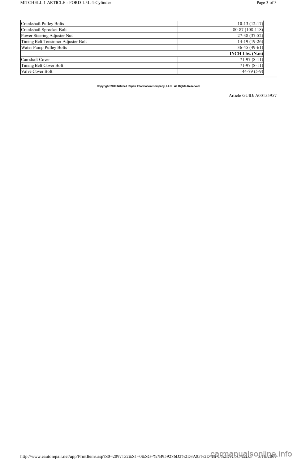
Crankshaft Pulley Bolts10-13 (12-17)
Crankshaft Sprocket Bolt80-87 (108-118)
Power Steering Adjuster Nut27-38 (37-52)
Timing Belt Tensioner Adjuster Bolt14-19 (19-26)
Water Pump Pulley Bolts36-45 (49-61)
INCH Lbs. (N.m)
Camshaft Cover71-97 (8-11)
Timing Belt Cover Bolt71-97 (8-11)
Valve Cover Bolt44-79 (5-9)
Copyr ight 2009 Mitchell Repair Information Company, LLC. All Rights Reserved.
Article GUID: A00155957
Page 3 of 3 MITCHELL 1 ARTICLE - FORD 1.3L 4-Cylinder
3/10/2009 http://www.eautorepair.net/app/PrintItems.asp?S0=2097152&S1=0&SG=%7B959286D2%2D3A85%2D4BFC%2D9C5C%2D
...
Page 148 of 454

Removal
Drain radiator and remove negative battery cable. Disconnect throttle cable. Remove air duct from throttle body. Disconnect throttle position
sensor/switch connector. Mark all coolant and vacuum hoses for reassembly reference and remove from throttle body. See Fig. 4
. Remove
intake plenum bolts and remove intake plenum and gasket.
Installation
To install, reverse removal procedure. Use NEW intake plenum-to-intake manifold gasket. Tighten bolts to specification, see TORQUE
SPECIFICATIONS at end of article.
OXYGEN (O2) SENSOR
Removal & Installation
Disconnect negative battery cable. Disconnect wire harness connector, and remove oxygen sensor. If exhaust sensor is difficult to remove, use
rust penetrant to avoid possible damage to exhaust threads. If new sensor is not pre-coated with anti-seize, apply anti-seize compound to
sensor threads. DO NOT remove anti-seize from sensor. To install, tighten sensor and attach wire harness connector.
THROTTLE BODY
Removal & Installation
Drain radiator and remove negative battery cable. Remove resonance chamber. Disconnect throttle cable. Remove air duct. Mark all coolant
and vacuum hoses for reassembly reference and remove from throttle body. Disconnect throttle position sensor/switch connector. Remove
throttle body nuts and bolts. Remove throttle body and gasket. To install, reverse removal procedure using NEW throttle body-to-intake
plenum gasket.
THROTTLE POSITION SENSOR/SWITCH
Removal & Installation
Disconnect negative battery cable. Disconnect throttle position sensor/switch connector. Remove attaching bolts. Remove sensor/switch from
throttle body. To install, reverse removal procedure.
TURBOCHARGER
Removal
1. Drain radiator and remove negative battery cable. Remove throttle body air intake tube. Disconnect intercooler hose from turbocharger
assembly. Disconnect O2 sensor. Remove lower heat shield retaining bolts and lower heat shield from turbocharger. Remove upper heat
shield retaining bolts and upper heat shield from exhaust manifold.
2. Slide O2 sensor wire and guide through upper heat shield. Remove side heat shield retaining bolts from turbocharger, and remove sid e
heat shield. Remove power steering belt. Remove power steering pump through bolt and adjuster nuts and bolts. Disconnect lower
radiator hose from water pump.
3. Pull pump from bracket, and position pump to access mounting bracket retaining nut and bolts. Remove mounting bracket-to-engine nut
and bolts and remove bracket. Remove air cleaner duct retaining screws. Loosen clamp at turbocharger and move duct tube out of way.
Disconnect coolant supply hose at turbocharger.
4. Remove bolt and sealing washers attaching oil supply line at engine block. Raise vehicle on hoist. Remove nuts and washers from
exhaust pipe flange. Remove bolts attaching exhaust hanger to engine block. Slide rubber exhaust hangers from catalytic converter. Pull
exhaust pipe downward and to left side of vehicle. Disconnect oil return hose from turbocharger. Disconnect coolant return hose fro m
turbocharger.
5. Remove turbocharger support bracket retaining bolts. Remove coolant by-pass tube outlet-to-water pump bolts. Lower vehicle. Loosen
retaining clamp bolt on coolant by-pass tube at rear of cylinder head. Remove 11 retaining nuts from exhaust manifold. Position coolant
by-pass tube out of way after pulling bracket from exhaust stud.
6. Remove exhaust manifold by pulling off studs and moving assembly towards right side of engine compartment, clearing cooling fan.
With assembly removed from vehicle, remove turbocharger-to-exhaust manifold nuts. Separate assembly and discard gasket.
Installation
1. Install NEW gasket on exhaust manifold and install turbocharger onto studs. Install turbocharger-to-exhaust manifold nuts. Remo ve o il
supply line from turbocharger. Install NEW exhaust gasket on cylinder head. Install turbocharger and exhaust manifold assembly onto
studs. Install coolant by-pass tube bracket onto exhaust stud. Install 11 retaining nuts onto exhaust manifold.
2. Securely tighten heater tube clamp bolt. Raise vehicle. Install coolant by-pass tube outlet-to-water pump bolts. Install turbocharger
support bracket retaining bolts. Connect coolant return hose to turbocharger. Connect oil return hose to turbocharger. Install exhaust
pipe onto turbocharger, and hand tighten nuts and washers. Install bolts attaching exhaust hanger to engine block.
3. Slide rubber exhaust hangers onto catalytic converter. Tighten exhaust pipe nuts and washers. Lower vehicle. Install bolt and sealing
washers attaching oil supply line at engine block. Install oil supply line onto turbocharger. To complete installation, reverse removal
procedure. Tighten bolts and nuts to specification, see TORQUE SPECIFICATIONS
at end of article. NOTE:T o prevent dust and dirt from entering intake m anifold ports, cover ports with clean cloth after
rem oving intake plenum .
WARNING:DO NOT rem ove oxygen sensor when engine is hot.
NOTE:Clean throttle body exterior before rem oval.
CAUT ION: Before installing turbocharger, put .8 oz. (25 m l) engine oil into turbocharger oil inlet.
Page 4 of 5 MITCHELL 1 ARTICLE - N - REMOVE/INSTALL/OVERHAUL 1991 ENGINE PERFORMANCE Ford/Mercury Removal, O
...
3/10/2009 http://www.eautorepair.net/app/PrintItems.asp?S0=2097152&S1=0&SG=%7B959286D2%2D3A85%2D4BFC%2D9C5C%2D
...
Page 149 of 454

VANE AIRFLOW (VAF) METER
Removal
1. Disconnect negative battery cable. On Capri, disconnect primary and secondary wires from coil. On Festiva, disconnect VAF wire
harness connector. Remove air duct.
2. On Capri, remove retaining bolt and ground wire from air cleaner cover. Remove air cleaner cover bolts and air cleaner cover. From
inside of air cleaner cover, remove VAF meter retaining nuts. On Festiva, remove attaching bolt and 4 nuts. Remove vane airflow met er.
Installation
To install, reverse removal procedure. Position new gasket over VAF mounting studs. Tighten bolts and nuts to specification, see TORQUE
SPECIFICATIONS at end of article.
TORQUE SPECIFICATIONS
TORQUE SPECIFICATIONS NOTE:For all on-vehicle adjustm ents not covered in this article, see ADJUST MENT S article in the ENGINE
PERFORMANCE Section.
ApplicationFt. Lbs. (N.m)
Coolant By-Pass Tube Outlet-To-Water Pump Bolts14-19 (19-26)
Distributor Mounting Bolts14-19 (19-26)
Exhaust Manifold Retaining Nuts29-42 (39-57)
Exhaust Pipe Nuts18-25 (24-34)
Fuel Line-To-Fuel Filter Bolt18-25 (24-34)
Fuel Pressure Regulator Nut(1)
Fuel Rail Retaining Bolt14-19 (19-26)
Heat Shield Bolts14-19 (19-26)
Intake Plenum Bolts/Nuts11-16 (15-22)
Oil Supply Line-To-Turbocharger Bolt12-17 (16-23)
Oxygen Sensor(1)
Power Steering Pump Bracket-To-Engine Bolts/Nut35-48 (47-65)
Throttle Body Bolt/Nuts12-17 (16-23)
Turbocharger Support Bracket Bolts32-45 (43-61)
Turbocharger-To-Exhaust Manifold Nuts20-25 (27-34)
INCH Lbs. (N.m)
Barometric Pressure (BP) Sensor Nut54-84 (6-9)
MAP Sensor Nuts54-84 (6-9)
Oil Supply Line-To-Engine Block Bolt104-156 (12-18)
Vane Airflow Meter Nuts110-152 (12-18)
(1)Information not available from manufacturer.
Copyr ight 2009 Mitchell Repair Information Company, LLC. All Rights Reserved.
Article GUID: A00022705
Page 5 of 5 MITCHELL 1 ARTICLE - N - REMOVE/INSTALL/OVERHAUL 1991 ENGINE PERFORMANCE Ford/Mercury Removal, O
...
3/10/2009 http://www.eautorepair.net/app/PrintItems.asp?S0=2097152&S1=0&SG=%7B959286D2%2D3A85%2D4BFC%2D9C5C%2D
...
Page 222 of 454
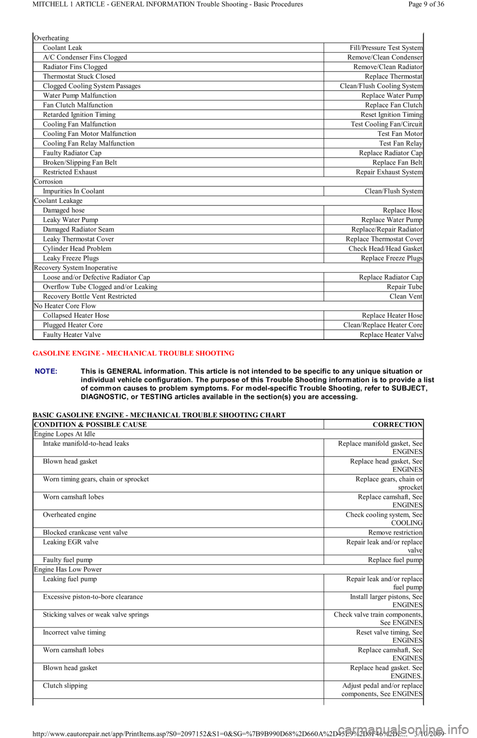
GASOLINE ENGINE - MECHANICAL TROUBLE SHOOTING
BASIC GASOLINE ENGINE - MECHANICAL TROUBLE SHOOTING CHART
Overheating
Coolant LeakFill/Pressure Test System
A/C Condenser Fins CloggedRemove/Clean Condenser
Radiator Fins CloggedRemove/Clean Radiator
Thermostat Stuck ClosedReplace Thermostat
C l o gge d C o o l in g S yst e m P a ssa ge sClean/Flush Cooling System
Water Pump MalfunctionReplace Water Pump
Fan Clutch MalfunctionReplace Fan Clutch
Retarded Ignition TimingReset Ignition Timing
Cooling Fan MalfunctionTest Cooling Fan/Circuit
Cooling Fan Motor MalfunctionTest Fan Motor
Cooling Fan Relay MalfunctionTest Fan Relay
Faulty Radiator CapReplace Radiator Cap
Broken/Slipping Fan BeltReplace Fan Belt
Restricted ExhaustRepair Exhaust System
Corrosion
Impurities In CoolantClean/Flush System
Coolant Leakage
Damaged hoseReplace Hose
Leaky Water PumpReplace Water Pump
Damaged Radiator SeamReplace/Repair Radiator
Leaky Thermostat CoverReplace Thermostat Cover
Cylinder Head ProblemCheck Head/Head Gasket
Leaky Freeze PlugsReplace Freeze Plugs
Recovery System Inoperative
Loose and/or Defective Radiator CapReplace Radiator Cap
Overflow Tube Clogged and/or LeakingRepair Tube
Recovery Bottle Vent RestrictedClean Vent
No Heater Core Flow
Collapsed Heater HoseReplace Heater Hose
Pl u gge d He a t e r C o r eClean/Replace Heater Core
Faulty Heater ValveReplace Heater Valve
NOTE:This is GENERAL inform ation. This article is not intended to be specific to any unique situation or
individual vehicle configuration. T he purpose of this T rouble Shooting inform ation is to provide a list
of com m on causes to problem sym ptom s. For m odel-specific T rouble Shooting, refer to SUBJECT ,
DIAGNOST IC, or T EST ING articles available in the section(s) you are accessing.
CONDITION & POSSIBLE CAUSECORRECTION
Engine Lopes At Idle
In t ake man ifo l d -t o -h ead l eaksReplace manifold gasket, See
ENGINES
Blown head gasketReplace head gasket, See
ENGINES
Worn timing gears, chain or sprocketReplace gears, chain or
sprocket
Worn camshaft lobesReplace camshaft, See
ENGINES
Overheated engineCheck cooling system, See
COOLING
Blocked crankcase vent valveRemove restriction
Le a kin g E GR va l veRepair leak and/or replace
va l ve
Faulty fuel pumpReplace fuel pump
Engine Has Low Power
Leaking fuel pumpRepair leak and/or replace
fu el p u mp
Excessive piston-to-bore clearanceInstall larger pistons, See
ENGINES
Sticking valves or weak valve springsCheck valve train components,
See ENGINES
Incorrect valve timingReset valve timing, See
ENGINES
Worn camshaft lobesReplace camshaft, See
ENGINES
Blown head gasketReplace head gasket. See
ENGINES.
Clutch slippingAdjust pedal and/or replace
components, See ENGINES
Page 9 of 36 MITCHELL 1 ARTICLE - GENERAL INFORMATION Trouble Shooting - Basic Procedures
3/10/2009 http://www.eautorepair.net/app/PrintItems.asp?S0=2097152&S1=0&SG=%7B9B990D68%2D660A%2D45E9%2D8F46%2DE
...
Page 229 of 454
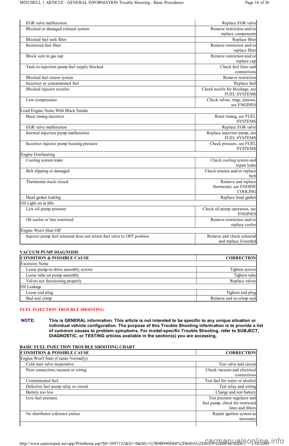
VACUUM PUMP DIAGNOSIS
FUEL INJECTION TROUBLE SHOOTING
BASIC FUEL INJECTION TROUBLE SHOOTING CHART
EGR valve malfunctionReplace EGR valve
Blocked or damaged exhaust systemRemove restriction and/or
replace components
Blocked fuel tank filterReplace filter
Restricted fuel filterRemove restriction and/or
replace filter
Block vent in gas capRemove restriction and/or
replace cap
Tank-to-injection pump fuel supply blockedCheck fuel lines and
connections
Blocked fuel return systemRemove restriction
Incorrect or contaminated fuelReplace fuel
Blocked injector nozzlesCheck nozzle for blockage, see
FUEL SYSTEMS
Low compressionCheck valves, rings, pistons,
see ENGINES
Loud Engine Noise With Black Smoke
Basic timing incorrectReset timing, see FUEL
SYSTEMS
EGR valve malfunctionReplace EGR valve
Internal injection pump malfunctionReplace injection pump, see
FUEL SYSTEMS
Incorrect injector pump housing pressureCheck pressure, see FUEL
SYSTEMS
Engine Overheating
Cooling system leaksCheck cooling system and
repair leaks
Belt slipping or damagedCheck tension and/or replace
belt
Thermostat stuck closedRemove and replace
thermostat, see ENGINE
COOLING
Head gasket leakingReplace head gasket
Oil Light on at Idle
Low oil pump pressureCheck oil pump operation, see
ENGINES
Oil cooler or line restrictedRemove restriction and/or
replace cooler
Engine Won't Shut Off
Injector pump fuel solenoid does not return fuel valve to OFF positionRemove and check solenoid
and replace if needed
CONDITION & POSSIBLE CAUSECORRECTION
Excessive Noise
Loose pump-to-drive assembly screwsTighten screws
Loose tube on pump assemblyTighten tube
Valves not functioning properlyReplace valves
Oil Leakage
Loose end plugTighten end plug
Bad seal crimpRemove and re-crimp seal
NOTE:This is GENERAL inform ation. This article is not intended to be specific to any unique situation or
individual vehicle configuration. T he purpose of this T rouble Shooting inform ation is to provide a list
of com m on causes to problem sym ptom s. For m odel-specific T rouble Shooting, refer to SUBJECT ,
DIAGNOST IC, or T EST ING articles available in the section(s) you are accessing.
CONDITION & POSSIBLE CAUSECORRECTION
Engine Won't Start (Cranks Normally)
Cold start valve inoperativeTest valve and circuit
Poor connection;vacuum or wiringCheck vacuum and electrical
connections
Contaminated fuelTest fuel for water or alcohol
Defective fuel pump relay or circuitTest relay and wiring
Battery too lowCharge and test battery
Low fuel pressureTest pressure regulator and
fuel pump, check for restricted
lines and filters
No distributor reference pulsesRepair ignition system as
necessary
Page 16 of 36 MITCHELL 1 ARTICLE - GENERAL INFORMATION Trouble Shooting - Basic Procedures
3/10/2009 http://www.eautorepair.net/app/PrintItems.asp?S0=2097152&S1=0&SG=%7B9B990D68%2D660A%2D45E9%2D8F46%2DE
...
Page 230 of 454

IGNITION SYSTEM TROUBLE SHOOTING
Open coolant temperature sensor circuitTest sensor and wiring
Shorted W.O.T. switch in T.P.S.Disconnect W.O.T. switch,
engine should start
Defective ECMReplace ECM
Fuel tank residual pressure valve leaksTest for fuel pressure drop
after shut down
Hard Starting
Disconnected hot air tube to air cleanerReconnect tube and test
control valve
Defective Idle Air Control (IAC) valveTest valve operation and
circuit
Shorted, open or misadjusted T.P.S.Test and adjust or replace
T.P.S.
EGR valve openTest EGR valve and control
circuit
Poor Oxygen sensor signalTest for shorted or circuit
Incorrect mixture from PCV systemTest PCV for flow, check
sealing of oil filter cap
Poor High Speed Operation
Low fuel pump volumeFaulty pump or restricted fuel
lines or filters
Poor MAP sensor signalTest MAP sensor, vacuum
hose and wiring
Poor Oxygen sensor signalTest for shorted or open
sensor or circuit
Open coolant temperature sensor circuitTest sensor and wiring
Faulty ignition operationCheck wires for cracks or poor
con- nections, test secondary
voltage with oscilloscope
Contaminated fuelTest fuel for water or alcohol
Intermittent ECM groundTest ECM ground connection
for resistance
Restricted air cleanerReplace air cleaner
Restricted exhaust systemTest for exhaust manifold back
pressure
Poor MAF sensor signalCheck leakage between sensor
and manifold
Poor VSS signalIf tester for ALCL hook-up is
available check that VSS
reading matches speedometer
Ping or Knock on Acceleration
Poor Knock sensor signalTest for shorted or open
sensor or circuit
Poor Baro sensor signalTest for shorted or open
sensor or circuit
Improper ignition timingSee VEHICLE EMISSION
CONTROL LABEL (where
applicable)
Check for engine overheating problemsLow coolant, loose belts or
electric cooling fan inoperative
NOTE:For additional electronic fuel injection trouble shooting inform ation, see the appropriate article in the
ENGINE PERFORMANCE section (not all vehicles have Com puter Engine Control articles). Inform ation
is provided there for diagnosing fuel system problem s on vehicles with electronic fuel injection.
NOTE:This is GENERAL inform ation. This article is not intended to be specific to any unique situation or
individual vehicle configuration. T he purpose of this T rouble Shooting inform ation is to provide a list
of com m on causes to problem sym ptom s. For m odel-specific T rouble Shooting, refer to SUBJECT ,
DIAGNOST IC, or T EST ING articles available in the section(s) you are accessing.
Page 17 of 36 MITCHELL 1 ARTICLE - GENERAL INFORMATION Trouble Shooting - Basic Procedures
3/10/2009 http://www.eautorepair.net/app/PrintItems.asp?S0=2097152&S1=0&SG=%7B9B990D68%2D660A%2D45E9%2D8F46%2DE
...