Page 41 of 57
41
Level Control Systems
Single Axle Air Suspension (E65/E66)
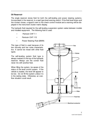
Purpose of the System
The single axle air suspension system used on the the E65/E66 is a further enhancement
of the previous single axle air suspension system used on the the E39 and X5. The com-
ponents used are similar to the Single Axle EHC System on the E53. The E65/E66 Air sus-
pension consists of the following components:
Air Supply System (LVA)
Control Unit (EHC)
Two Air Springs
Two Ride Height Sensors
CC Display/Telltale Icon
Page 42 of 57
Page 43 of 57
43
Level Control Systems
Components (E65/E66)
Air Supply Unit (LVA)
The air supply unit is located in the spare tire recess and consists of the following compo-
nents:
Protective cover with internal acoustic
insulation
Lid
Rubber-mounted component carrier
Compressor Unit
Compressor Relay
Solenoid Valve Block
IndexExplanationIndexExplanation
1Rubber Mount6Air Drier
2Component Carrier7Compressor
3Compressor Relay8Solenoid Valve, Right
4Electric Motor9Solenoid Valve, Left
5Air Cleaner
Page 44 of 57

44
Level Control Systems
Control Unit
The EHC control module is located in the right rear luggage compartment area in the mod-
ule carrier next to the battery. On the E65/E66, the control module is connected to the K-
CAN S. The EHC control module receives the following information:
Vehicle Ride Height
Load Cutout Signal
Terminal 15 ON/OFF
Vehicle Speed
Lateral Acceleration
“Engine Running” Signal
Flap Status (Doors/Trunk)
The Control unit decides on a case by
case basis whether a control opera-
tion is required in order to compen-
sate changes in load. It prevents
intervention in the case of other caus-
es. This makes it possible to adapt
the frequency, specified height, toler-
ance thresholds and battery load opti-
mally by means of the control opera-
tion to the relevant situation.
In addition to handling the self levelling
suspension, the control module moni-
tors the system components as well
as storing a displaying faults. The
control module has full diagnostic
capability.
The EHC module is a 26 pin module
with an ELO type connector. The
module is connected to the K CAN S.
The majority of the input messages
are from the K CAN S Bus.
EHC Module Location
Page 45 of 57

45
Level Control Systems
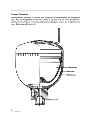
Air Springs
An identifying feature of the E65/E66 air spring is the internally guided air bellows. Internally
guided means that the bellows is guided in an aluminum casing. The bellows is support-
ed on this casing. This prevents the compression forces from weighing heavily on the bel-
lows.
This process allows the bellows to be manufactured from a thin, flexible diaphragm which
can react to minimal shocks and in this way provide a more comfortable suspension.
The diaphragm is composed of only one fabric layer embedded in rubber. The fibers with-
in the fabric run longitudinally along the spring strut. The bellows is therefore known as an
axial air bellows.
The bottom end of the air spring strut is enclosed
in a bellows in order to protect the diaphragm
against the mechanical effects of fouling (sand, dirt
etc.). The lower end of the bellows incorporates
small holes for pressure compensation in the
space between the roll piston and bellows. The
action of the bellows rolling in this space produces
pressure differences.
The bellows together with the roll piston contains
a volume of air that is sufficient for optimum sus-
pension.
A residual pressure holding valve on the air spring
strut prevents it from being depressurized. The air
spring strut remains under pressure in the event of
a loss of pressure in the system. The residual
pressure is 3.25 +/- 0.75 bar. This ensures that
the bellows is not damaged when the car is still
being moved.
The residual pressure holding valve is secured with
Loctite and must NOTbe removed.
The air spring strut is initially filled at the manufac-
turer to 10 bar. This pressure is reduced to 3.5 bar
when the spring strut is to be stored. Under this
pressure, the strut is extended to maximum
length.
The connection of the air spring struts to the air
supply unit (distributor block) is located on the left
of the luggage compartment under the flap on
which the wheel nut wrench is mounted.
Page 46 of 57

46
Level Control Systems
Ride Height Sensor
There are two ride height sensors, one for each rear wheel. The ride height sensor is actu-
ated by a coupling rod and sends a signal to the EHC control unit.
The sensor is a hall sensor which sends a DC Analog output voltage to the EHC module.
The voltage range is approximately .5 to 4.5 volts. The voltage increases with increasing
vehicle height and the nominal voltage at normal ride height is approximately 2.5 volts. The
right side rear sensor is a double sensor, the additional sensor is an input to the headlight
leveling systemand has it’s own power supply, ground and signal wires.
Check Control Messages
Control
UnitCauseVariable
Telltale IconCheck Control
MessageInformation in Control Display
EHC
Alive failure or
loss of function-
ality; transport
or belt mode setLevel Control
System failure“Level Control system failure”
Ground clearance and driving
comfort reduced. Avoid high
speed cornering. Have
checked by BMW Service as
soon as possible.
EHC
Level Control
System sensor
failure.Level Control
System Fault“Level Control System fault”
Possible reduction in driving
comfort. Have problem
checked by BMW Service.
Page 47 of 57
47
Level Control Systems
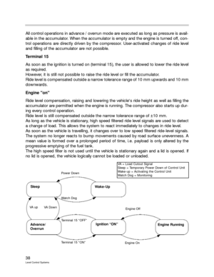
Control Mode Flow Chart
The following chart demonstrates the control sequences of the E65/E66 with single axle
rear air suspension.
Sleep
Post
Curve
Lift
Drive
Normal
Pre
Kerb
Page 48 of 57
48
Level Control Systems
Principle of Operation
Control Mode Overview
Control Modes
Ongoing control operations are not affected by transitions from one mode to another.
However, in the case of load cutout OFF, control operations are always concluded in order
to safeguard system deactivation. The control unit then sets the Sleep Mode.
Sleep
The vehicle is in Sleep mode at the latest when it has been parked for longer than 16 min-
utes with a door, hood or rear lid/hatch being operated or the terminal status changing.
This is the initial state of the control system. No control operation is being performed in
Sleep mode.
The control system goes into Pre-mode when a wake-up signal is received by the control
unit.
E39/E53 EHC I
(Single Axle)E65/E66
(single Axle)E53 EHC II
(Dual Axle)
SleepXXX
Wake-upX
PostX
PreXXX
Terminal 15 OnX
NormalXXX
DriveXXX
KerbXXX
CurveXXX
LiftXXX
TwistX
TrailerX
Off-RoadX
AccessX


Purpose of the System
The single axle air suspension system used on the the E65/E66 is a further enhancement
of the previous single axle a")


Air Supply Unit (LVA)
The air supply unit is located in the spare tire recess and consists of the following compo-
nents:
Protective cover with internal")

