Page 1127 of 2103
AUTOMATIC TRANSAXLE
DIAGNOSTIC TROUBLESHOOTING FLOW
.
.Gather information from customer.
Verify complaint
Communication withscan tool not possible
Record the diagnostic trouble code
and fail-gafe code. (Refer to ,
Diagnostic trouble code outputNo diagnostic trouble
Erase the diagnostic trouble code code displayed(Refer to
Basic inspection item adjustment(Refer to
Abnormality exists
(no diagnostic trouble code)
Road test (Refer
Abnormality exists
(diagnostic trouble
code present)
Diagnostic trouble
Recheck trouble codeswhich were recorded before the roadt e s t .
Search for cause.
FoundNot found
NG
OK
‘CompletedConfirmation test (road test)
TSB Revision
Page 1128 of 2103
AUTOMATIC TRANSAXLE ENGINE (NON-TURBO)> Troubleshooting
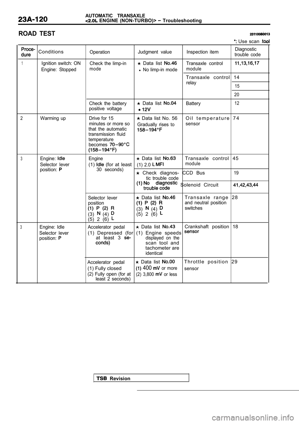
ROAD TEST
Use scan
ConditionsOperationJudgment value Inspection item Diagnostic
trouble code
1Ignition switch: ON Check the limp-in Data list Transaxle control
Engine: Stoppedmodel No limp-in modemodule
Transaxle control 14
relay15
20
Check the battery Data list Battery12
positive voltage
2Warming up Drive for 15 Data list No. 56 O i l t e m p e r a t u r e 7 4
minutes or more so
that the automatic Gradually rises to
sensor
transmission fluid
temperature
becomes
3Engine:Engine Data list Transaxle control 45
Selector lever(1) (for at least(1) 2.0 module
position:30 seconds) Check diagnos- CCD Bus19
tic trouble code
Solenoid Circuit
Selector lever
position
(3) (4)
(5) 2 (6)
Data list T r a n s a x l e r a n g e 2 8
and neutral position
(3) (4) switches
(5) 2 (6)
3Engine: Idle Accelerator pedal Data list Crankshaft position 18
Selector lever(1) Depressed (for (1) Engine speeds
position:at least 3 displayed on the
scan tool and
tachometer are
identical
Accelerator pedal
Data list T h r o t t l e p o s i t i o n 2 9
(1) Fully closed
400 or moresensor
(2) Fully open (for at least 2 seconds)
(2) 3,800 or less
Revision
Page 1132 of 2103
AUTOMATIC TRANSAXLE
ENGINE Troubleshooting
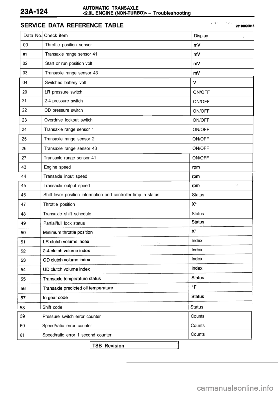
SERVICE DATA REFERENCE TABLE
Data No. Check itemDisplay
00 Throttle position sensor
01Transaxle range sensor 41
02Start or run position volt
03Transaxle range sensor 43
04 Switched battery volt
20 pressure switch
ON/OFF
212-4 pressureswitch
ON/OFF
22ODpressureswitch
ON/OFF
23 Overdrive lockout switch
ON/OFF
24Transaxle range sensor 1ON/OFF
25 Transaxle range sensor 2
ON/OFF
26Transaxle range sensor 43ON/OFF
27 Transaxle range sensor 41
ON/OFF
43 Engine speed
44Transaxle input speed
45Transaxle output speed
46Shift lever position information and controller lim
p-in status
Status
47Throttle position
48Transaxle shift schedule
Status
Partial/full lock status
58Shift code Status
59
60
61
Pressure switch error counter Counts
Speed/ratio error counter Counts
Speed/ratio error 1 second counter Counts
TSB Revision
Page 1133 of 2103
AUTOMATIC TRANSAXLE
ENGINE (NON-TURBO)> Troubleshooting
Data Check item
62Speed/ratio error 15 second counter
‘Display
Counts
63Engine model identification
64General flag
E n g i n e M o d e l
S t a t u s
65Actuator test statusIStatusI
66Element mask register StatusI
67
EEPROM flag register
68Output teeth count StatusTeeth
69Wheel speed coefficient in EEPROM
Coefficient
Current production MY/application MY Model Year
ACTUATOR R
E FER E N CE TA BL E
Item No.
Check item Drive contents Check conditions Remarks
01 solenoid
022-4 solenoid
03UD solenoid
04OD solenoid Current flows to the solenoid
Engine:Check the actuator
for 6 seconds at 50% duty. Idle (Vehicle stopped)test status (Display)
Selector lever position:
range
Throttle opening angle: Fully closed
Page 1139 of 2103
AUTOMATIC TRANSAXLE
ENGINE
Code Scan tool 18Engine speed sensor circuit
No.General scan tool
Engine speed received at the PCM from the CKP over the CCD bus is less than 384 o f l Harness or connector between crankshaft
position sensor and TCM open or
. .
l of TCM
OK
Measure at the TCM connector l Disconnect the connector and
measure at the harness side.
l Voltage between (46) and ground.
S t a r t t h e e n g i n e .
O K :
C h e c k t h e l
OK
Road test (Refer to
Replace the TCM
Abnormality exists (no diagnostic trouble
. .
Abnormality exists(diagnostic troublecode present)
Recheckdiagnostictroublecodeswhich
were read before the road test
Diagnostic trouble
code output No diagnostic trouble
code displayed
TSB Revision
Page 1708 of 2103

ABS Troubfeshooting , .
INSPECTION PROCEDURE 7
Break operation is abnormal
[Comment]This varies depending on the driving conditions and the road surface conditions, soproblem diagnosis is difficult. However, if a normal diagnostic trouble code is displayed,carry out the following
l Malfunction of wheel speed l Malfunction of ABS rotor
l Malfunction of wheel bearing
of hydraulic Malfunction of ABS-ECU
NG Repair
(Refer to
Wheel speed sensor output voltage check [ R e p l a c e t h e w h e e l
Hydraulic unit check (Refer to 1NGABS rotor check (Refer to Replace the rotor.
O K NGWheel bearing end play check Refer to GROUP 26 On-vehicle Repair
Service.Refer to GROUP 27 On-vehicleIService.I
Check trouble symptom.
ABS-ECU connector l Disconnect the connector and
measure at the harness side.
l Resistance vaiue between termi-
nals
14-15, and
O KThe sensor harness and connector
should be moved while these checks
are carded out.
OK
Repair
TSB Revision
Repair
.
NG Repair
OK
Check trouble symptom.N G Replace ABS-ECU.
Page 1734 of 2103
ABS
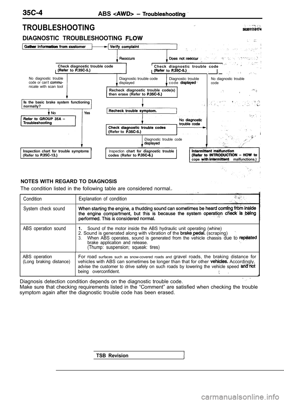
TROUBLESHOOTING
Check diagnostic trouble codeC h e c k d i a g n o s t i c t r o u b l e c o d e to to
No diagnostic troubleDiagnostic trouble codecode or can’t Diagnostic trouble
displayed c o d e
nicate with scan tool Recheck diagnostic trouble code(s)
then erase (Refer to
No diagnostic trouble
code
.
DIAGNOSTIC TROUBLESHOOTING
Gather information from customer
Is the basic brake system functioning
normallv?
(Refer to
Diagnostic trouble code
Inspection chart for trouble symptoms(Refer to Inspectionchart for diagnostic troubleII
codes (Refer to
cope malfunctions.)
NOTES WITH REGARD TO DIAGNOSIS
The condition listed in the following table are con sidered normal.
ConditionExplanation of condition
System check sound
TSB Revision
ABS operation soundSound of the motor inside the ABS hydraulic unit op erating (whine)2. Sound is generated along with vibration of the (scraping)
3.When ABS operates, sound is generated from the vehi cle chassis due to brake application and release.
(Thump: suspension; squeak: tires)
ABS operationFor road surfaces such as snow-covered roads and gravel roads, the braking distance for
(Long braking distance)vehicles with ABS can sometimes be longer than that for other Accordingly,
advise the customer to drive safely on such roads by lowering the vehicle speed
being overconfident.
. .
Diagnosis detection condition depends on the diagno stic trouble code.
Make sure that checking requirements listed in the “Comment” are satisfied when checking the trouble
symptom again after the diagnostic trouble code has been erased.
Page 1747 of 2103
, , .
PROCEDURE 7
Break operation is
[Comment] o f w h e e l This depending on the driving conditions and the road surface conditions, so ‘ M a l f u n c t i o n _ _
problem diagnosis is difficult. However, if a normal diagnostic trouble code is displayed,l
carry out the following Malfunction of bearing. . .l of: .
W h e e l s p e e d -NG: Repair(Refer to
N G N G speed sensor check(Refer to GROUP -Wheel SpeedReplace the wheel speed sensor.
OKSensor Check.)
OK
Hydraulic unit check (Refer to N GABS rotor check (Refer to Replace the rotor.
OK
Wheel bearing end play check
Refer to GROUP 26 On-vehicle Repair
Refer to GROUP 27
On-vehide
Service.
Check trouble symptom.
N G
ABS-ECU connector Disconnect the connector and measure at the harness side.
Resistance value between termi-nals and
NG Repair
O K
The sensor harness and connector s h o u l d b e m o v e d w h i l e t h e s e
inspections are carried out.
the .
TSB Revision