1990 MITSUBISHI ECLIPSE fuel cap
[x] Cancel search: fuel capPage 9 of 391

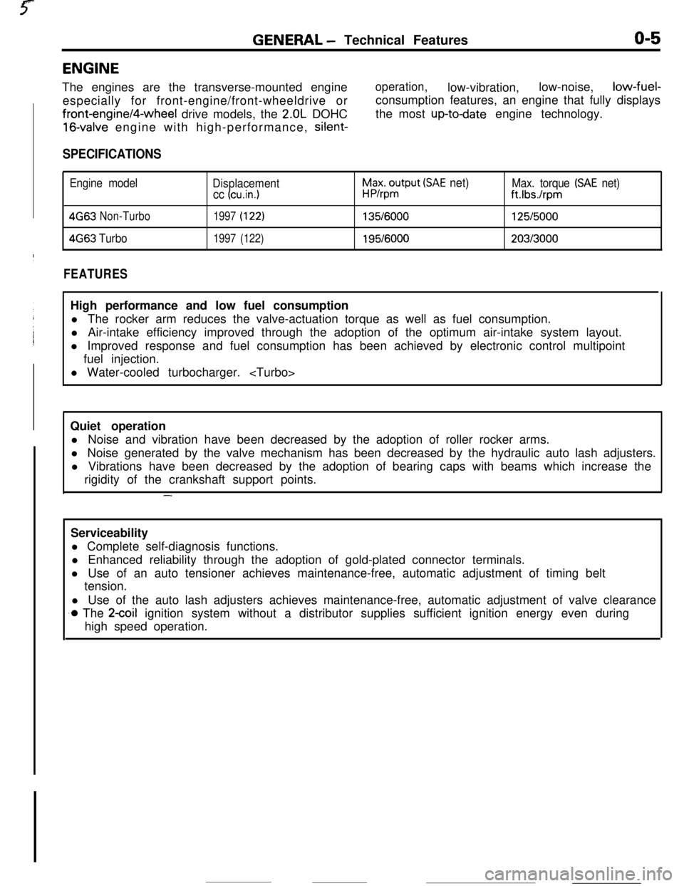
GENERAL - Technical Featureso-5ENGINE
The engines are the transverse-mounted engine
especially for front-engine/front-wheeldrive orfront-engine/4-wheel drive models, the
2.OL DOHC
16-valve engine with high-performance, silent-
operation,low-vibration,low-noise,low-fuel-
consumption features, an engine that fully displays
the most
up-todate engine technology.
SPECIFICATIONS
Engine model
Displacement
cc (cu.in.1
h$xo$put (SAE net)Max. torque (SAE net)
ft.Ibs./rpm
4G63Non-Turbo1997(122)135/6000125/5000
4663Turbo1997(122)195/6000203/3000
FEATURESHigh performance and low fuel consumption
l The rocker arm reduces the valve-actuation torque as well as fuel consumption.
l Air-intake efficiency improved through the adoption of the optimum air-intake system layout.
l Improved response and fuel consumption has been achieved by electronic control multipoint
fuel injection.
l Water-cooled turbocharger.
Quiet operation
l Noise and vibration have been decreased by the adoption of roller rocker arms.
l Noise generated by the valve mechanism has been decreased by the hydraulic auto lash adjusters.
l Vibrations have been decreased by the adoption of bearing caps with beams which increase the
rigidity of the crankshaft support points.
-Serviceability
l Complete self-diagnosis functions.
l Enhanced reliability through the adoption of gold-plated connector terminals.
l Use of an auto tensioner achieves maintenance-free, automatic adjustment of timing belt
tension.
l Use of the auto lash adjusters achieves maintenance-free, automatic adjustment of valve clearance
.o The 2coil ignition system without a distributor supplies sufficient ignition energy even during
high speed operation.
Page 18 of 391

o-14GENERAL - General Data and Specifications
tiems
Chassis
TireFront suspension
Type
Rear suspensionType
Brake
TypeFront
RearSteering
Gear type
Gear ratio
Fuel tankCapacity liters (gals.)
P205/55HR16 or
205l55VR 16Independent strut
3-Link
Torsion axleDisc
Disc
Rack and pinion
m
60 (16)
P205/55VR 16 or205155VR16Independent strut
3-Link
Torsion axleDisc
Disc
Rack and pinion
00
60 (16)
P205155VR16 or205155VR16Independent strut
Double wishbone
Disc
Disc
Rack and pinion
co
60 (16)ENGINE SPECIFICATIONS
Items
TypeNumber of cylinders
Boremm (in.)Stroke
mm (in.)Piston displacement
Compression ratio
Firing order
cm3 (cu.in.)
4G63 (2.OL) Non-Turbo1 4663 (2.OL) Turbo
In-line DOHC~ In-line DOHC
4‘4
85.0 (3.35)
85.0 (3.35)
88.0 (3.46)88.0 (3.46)
1,997 (122)
1,997 (122)
9.0
7.8l-3-4-2l-3-4-2
TRANSAXLE SPECIFICATIONS
Items
Type
Gear ratioTransfer ratio
gearFinal drive ratio
gear
1st
2nd
3rd4th5th
ReverseF5M22F5M33
W5M33F4A22
5-speed M/T5-speed M/T&speed ArF4-speed AiT
3.3633.038
3.0832.846
1.9471.8331.6841.581
1.2851.2171.1151 .ooo0.9390.8880.8330.686
0.756
0.7410.666
3.0833.166
’3.1662.176
-1.090
3.9413.4373.8663.562
Page 120 of 391

14-8
rFUEL SYSTEM
-Fuel Supply and Fuel Pressure Control
FUEL PUMP
This fuel pump is known as the in-tank type becauseit is located within the fuel tank itself, surrounded by
the fuel. For this reason, the pump operation noise
is well insulated, and it has excellent resistance to
vapor-locks.This type of pump is also called the “wet type”
because even its internal parts are in contact with
the fuel. With a construction that is the unification of
a ferrite-type DC motor and an impeller-type pump,
the pump itself is composed of the impeller, which
is driven by the motor, as well as the casing and the
cover. There are, in addition, a relief valve (a safety
valve for protection of the fuel-pressure circuit) and
a check valve (to maintain residual pressure).
The electric fuel pump has the following features:
l It has greater discharge pressure
mechanical-type fuel pump, as wellthan a
as lessdischarge pulsation.
lIt has a lower level of operation sound that the
electromagnetic type (Bendix type) of fuelpump.
PRESSURE-SUPPLY OF FUEL
When the impeller is caused to rotate by the motor,
a pressure differential develops at the upper. and
lower parts of the impeller, caused by the grooves in
the circumference of the impeller.
When this happens, a whirlpool effect is generated
within the fuel pump, causing the fuel pressure to
become higher, thereby causing the fuel to be
expelled from the pump chamber and to pass
through the motor, opening the check valve, and to
be discharged from the discharge port.
Discharge port
4Check!nRelief valve
DC mo
-lllll1 I/
Circum-ferential
flow pumr
II’ f-Pump
casing
J
Pumpcovert
lntakler 03R0071REWEF VALVE
If for some reason, such as an abnormal condition at the
_discharge side, the fuel were not to be discharged, the fuel
pressure within the fuel pump would become abnormally high.
Thus, when the pressure within the fuel pump reaches
450-600 kPa (64-85 psi), the relief valve opens and the
pressure escapes, so that, the fuel line pressure does not
increase to the regulated level or above.
CHECK VALVE
When the pump stops, the check valve is closed by spring
force, so that there is high pressure remaining within the fuel
line.By in this way maintaining a high pressure within the fuel line,
the restarting of the engine becomes easier, and vapor-locks at
high temperature are prevented.
-
-_..I
-~
Page 373 of 391

25-1
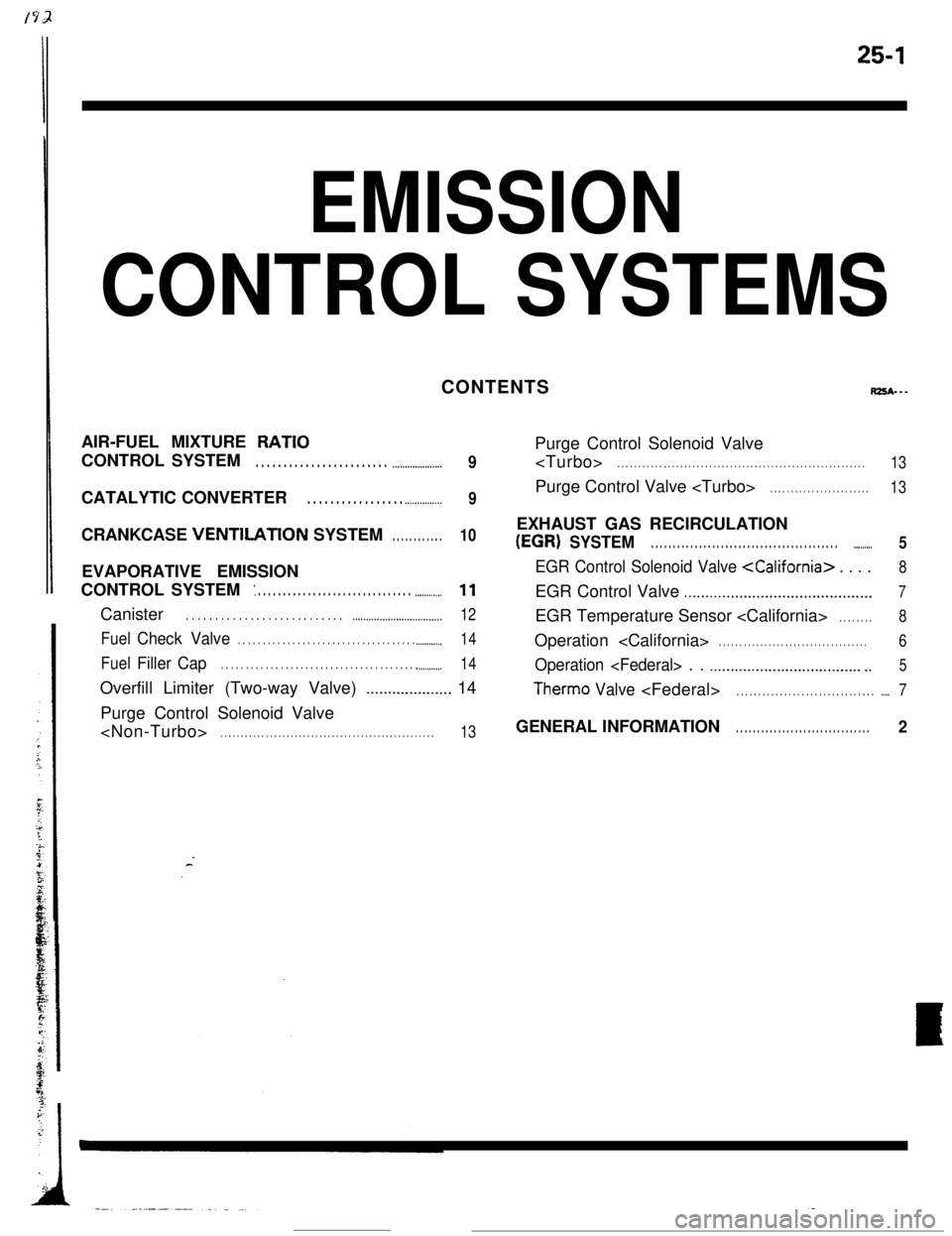
EMISSION
CONTROL SYSTEMSCONTENTS
RZSA---AIR-FUEL MIXTURE
RATIOCONTROL SYSTEM
. . . . . . . . . . . . . . . . . . . . . . . . .._.................9CATALYTIC CONVERTER
. . . . . . . . . . . . . . . . . .._............9CRANKCASE VENTlLATlON SYSTEM
. . . . . . . . . . . .10EVAPORATIVE EMISSION
CONTROL SYSTEM
: . . . . . . . . . . . . . . . . . . . . . . . . . . . . . . . ..-.........11Canister
. . . . . . . . . . . . . . . . . . . . . . . . . . . ..~...................._._...__..12
FuelCheck Valve. . . . . . . . . . . . . . . . . . . . . . . . . . . . . . . . . . . . .._.........14
FuelFiller Cap. . . . . . . . . . . . . . . . . . . . . . . . . . . . . . . . . . . . . . . . ..__....._..14Overfill Limiter (Two-way Valve)
_................... 14
Purge Control Solenoid Valve
. . . . . . . . . . . . . . . . . . . . . . . . . . . . . . . . . . . . . . . . . . . . . . . . . . . .13Purge Control Solenoid Valve
. . . . . . . . . . . _ . . . . . . . . . . . . . . . . . . . . . . . . . . . . . . . . . . . . . . . . . . . . . . . .13Purge Control Valve
. . . . . . . . . . . . . . . . . . . . . . . .13EXHAUST GAS RECIRCULATION
(EGR) SYSTEM. . . . . . . . . . . . . . . . . . . . . . . . . . . . . . . . . . . . . . . . . . . ..-......5
EGR Control Solenoid Valve
..,.........................................7EGR Temperature Sensor
. . . . . . . .8Operation
. . . . . . . . . . . . . . . . . . . . . . . . . . . . . . . . . . . .6
Operation
Therm0 Valve
. . . . . . . . . . . . . . . . . . . . . . . . . . . . . . . .2
Page 375 of 391

25-1
Eh/llSSlON
CONTROL SYSTEMS
rps*---
AIR-FUEL MIXTURE RATIO
_ . . . . . . . . . . . . . . . . . . . . . . . . . . . . . . . . . . .
CATALYTIC CONVERTER . . . . . . . . . . . . . . . . . . . . . . . . . . . . . . . .
._ _.__.____.
EVAPORATIVE EMISSION
: . . . . . . . . . . . . . . .._............. _ _.I.........
Canister . . . . . . . . . . . . . . . . . . . . . . . . . . . . . . . . . . . . \
. . . . . . . . . . . . . . . . . . . ..-..
Fuel Check Valve . . .._......._....._......__...._.__.............
Fuel Filler CapI.........._........................................
Overfill Limiter (Two-way Valve)_......._._.._._....
Purge Control Solenoid Valve
.._. _...
9
_..._............................................... 5
EGR Control Solenoid Valve
EGR Control Valve . . . . . . . . . . . . . . .._........................... 7
EGR Temperature Sensor
.._................ 6
Operation
Therm0 Valv e
GENERAL INFORMATIO N. . . . . . . . . . . . . . . . . . . . . . . . . . . . . . . . 2
Page 385 of 391

__..--. -._ _^__. __--- -._ _..EMISSION CONTROL SYSTEMS
- Evaporative Emission Control Svsvem25-l 1
,VAPORATlVE EMISSION CON-
TROL SYSTEMIn order to prevent the escape of fuel vapor from the
fuel system into the atmosphere. the evaporative
emission control system consists of a charcoal
canister, a purge control solenoid valve, etc.
When the fuel vapors generated inside the fuel tank
fill the tank, they press and open the overfill limiter’s
valve and pass to the canister, where they are
absorbed into and accumulated by the charcoal.
Because the purge control solenoid valve is ON
(open) when the engine is running, as a
conse-
Non-TurboAir cleaner
Fuel injector
Canister
Charcoal
/Purge control tsolenoid valve r
RZSGAAB
quence of the purge air being taken in from the
canister in accordance with the intake negative
pressure (vacuum), the fuel vapors accumulated in
the canister are taken from the charcoal and are alsotaken into the intake manifold.
Note that the purge control solenoid valve is OFF
(closed) when the engine is cold and during idling,
and so fuel vapors are not taken into the intake
manifold at that time.
Overfill
limiter(Two-way valve)
Fuel check valveFilter
- Fuel vapor
*---- Purge air
Page 388 of 391

--.25-14EMISSION CONTROL SYSTEMS
- Evaporative Emisson Control System
Pressure valveTo overfill
’ limiter
40
” Ball
Bail
\From fuel tank03E51fOVERFILL LIMITER (TWO-WAY VALVE)
The overfill limiter consists of a pressure valve and a vacuum
valve. The pressure valve is designed to open when the fuel
tank internal pressure has increased over the normal pressure
and the vacuum valve opens when a vacuum has been
producted in the tank.
FUEL CHECK VALVE
The fuel check valve is used to prevent fuel leaks if the vehicle
rolls over. This valve is connected in the fuel vapor line
(between canister and overfill limiter) and is installed on thefirewall.
The fuel check valve contains two balls, as shown in the
illustration. Under normal conditions, the fuel vapor passage in
the valve is opened, but if roll-over occurs one of the balls
closes the fuel passage, thus preventing fuel leaks.
FUEL FILLER CAPThe fuel filler cap is equipped with a relief valve to prevent the
escape of fuel vapor into the atmosphere.
.
-