1990 MITSUBISHI ECLIPSE oil pressure
[x] Cancel search: oil pressurePage 280 of 391

-
!-I
I!I
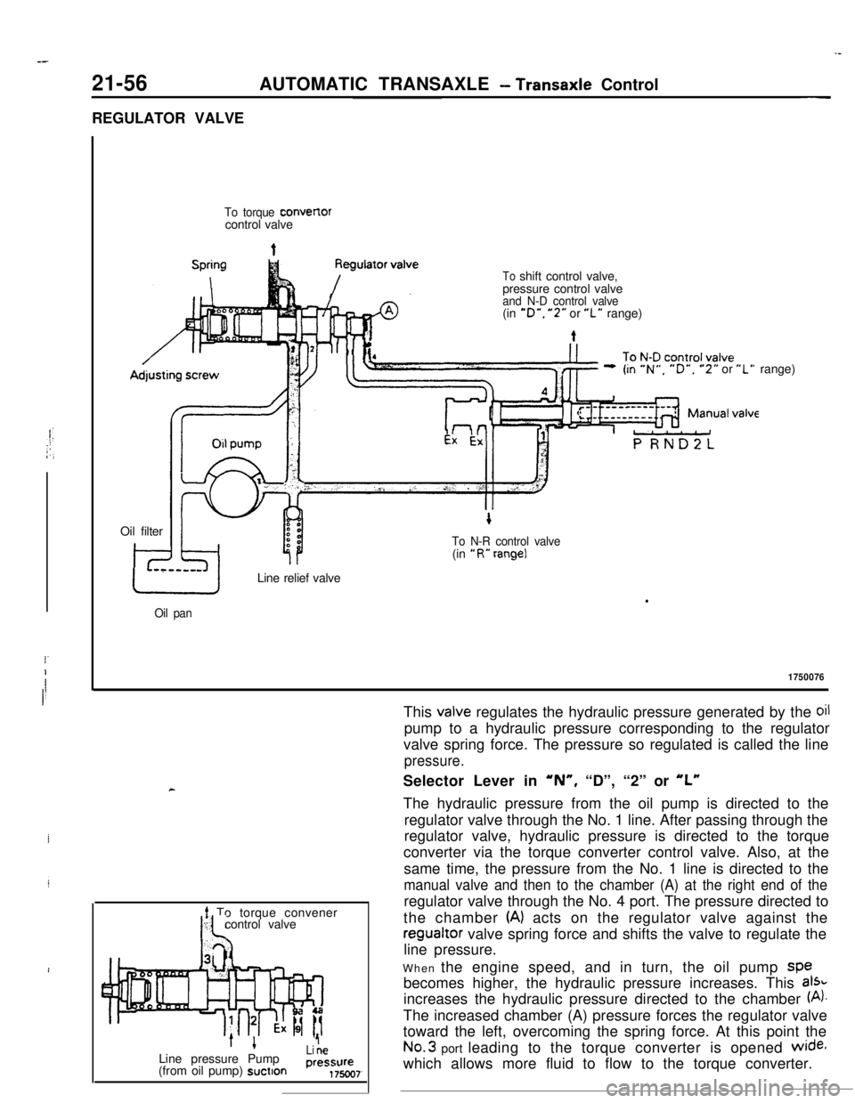
21-56AUTOMATIC TRANSAXLE - Transaxle Control~-REGULATOR VALVE
To torque convener
control valve
t
Toshift control valve,
pressure control valve
and N-D control valve(in “D”. ”2” or “L” range)
“D”.“2” or “L” range)
Oil filter
I1
To N-R control valve(in “R” range)Line relief valve
Oil pan
l
1750076
! To torque convener
IL‘I:control valve
Line pressure Pump
Li Ae(from oil pump) suctionprest$$)7,This
valve regulates the hydraulic pressure generated by the oilpump to a hydraulic pressure corresponding to the regulator
valve spring force. The pressure so regulated is called the line
pressure.Selector Lever in
‘N”, “D”, “2” or “L”The hydraulic pressure from the oil pump is directed to the
regulator valve through the No. 1 line. After passing through the
regulator valve, hydraulic pressure is directed to the torque
converter via the torque converter control valve. Also, at the
same time, the pressure from the No. 1 line is directed to the
manual valve and then to the chamber (A) at the right end of theregulator valve through the No. 4 port. The pressure directed to
the chamber
(A) acts on the regulator valve against theregualtor valve spring force and shifts the valve to regulate the
line pressure.
When the engine speed, and in turn, the oil pump spe
becomes higher, the hydraulic pressure increases. This
aI%increases the hydraulic pressure directed to the chamber
(A).The increased chamber (A) pressure forces the regulator valve
toward the left, overcoming the spring force. At this point theNo.3 port leading to the torque converter is opened
wide+which allows more fluid to flow to the torque converter.
Page 281 of 391

AUTOMATIC TRANSAXLE - Transaxle Control21-57
-7.To torque convert,erLine pressure
’Pump(from oil pump) suction
1 To N-RI control valveLine pressure
(from oil pump)1750072
-#5
To N-Dcontrol
valve
To toraueconverter
AdjLine pressure
1+(from oil pump)Pumpsuction
1 ~7valve
To N-Dcontrol
valve
s
Line pressure
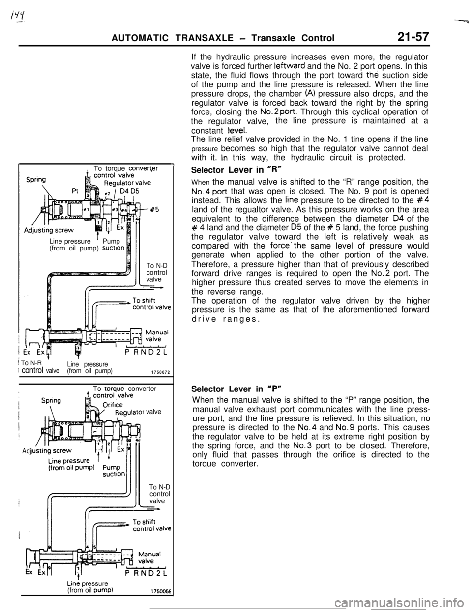
(from oil pump)If the hydraulic pressure increases even more, the regulator
valve is forced further leftward and the No. 2 port opens. In this
state, the fluid flows through the port toward the suction side
of the pump and the line pressure is released. When the line
pressure drops, the chamber
(A) pressure also drops, and the
regulator valve is forced back toward the right by the spring
force, closing the No.2
port. Through this cyclical operation of
the regulator valve,the line pressure is maintained at a
constant
tevel.The line relief valve provided in the No. 1 tine opens if the line
pressure becomes so high that the regulator valve cannot deal
with it.
In this way, the hydraulic circuit is protected.
Selector Lever in ‘R”
When the manual valve is shifted to the “R” range position, the
No.4 post that was open is closed. The No. 9 port is opened
instead. This allows the
tine pressure to be directed to the #4land of the regualtor valve. As this pressure works on the area
equivalent to the difference between the diameter
04 of the
# 4 land and the diameter 05 of the # 5 land, the force pushing
the regulator valve toward the left is relatively weak as
compared with the
force’the same level of pressure would
generate when applied to the other portion of the valve.
Therefore, a pressure higher than that of previously described
forward drive ranges is required to open the No.2 port. The
higher pressure thus created serves to move the elements in
the reverse range.
The operation of the regulator valve driven by the higher
pressure is the same as that of the aforementioned forward
drive ranges.
Selector Lever in
‘P”When the manual valve is shifted to the “P” range position, the
manual valve exhaust port communicates with the line press-
ure port, and the line pressure is relieved. In this situation, no
pressure is directed to the No.4 and No.9 ports. This causes
the regulator valve to be held at its extreme right position by
the spring force, and the No.3 port to be closed. Therefore,
only fluid that passes through the orifice is directed to the
torque converter.
Page 283 of 391

/ii>--..AUTOMATIC TRANSAXLE
- Transaxle Control21-59
Sxxrolvalve175022E
6
LmeFrom
TooilFrompressure torque- pump 2;0%conver-
termntrd
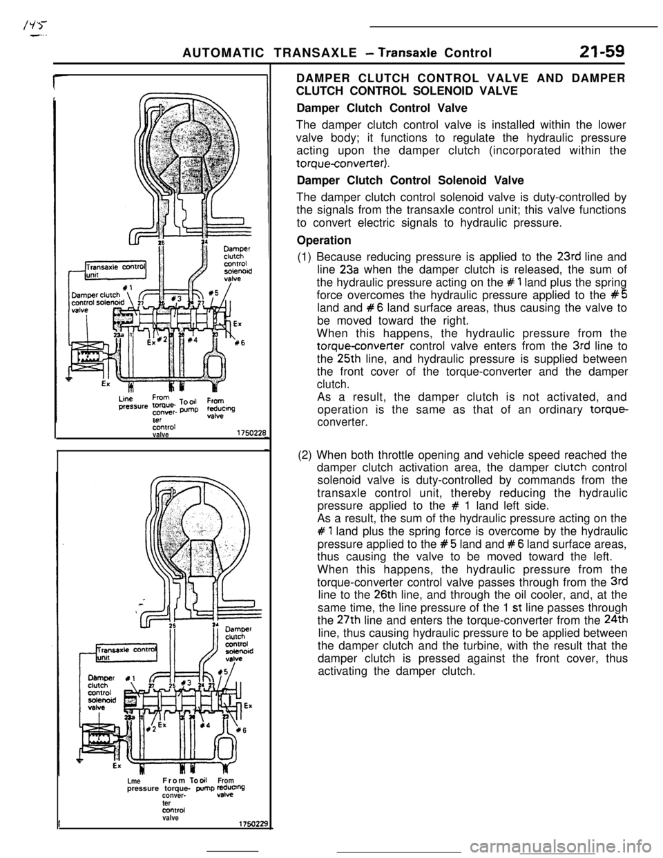
valveDAMPER CLUTCH CONTROL VALVE AND DAMPER
CLUTCH CONTROL SOLENOID VALVE
Damper Clutch Control Valve
The damper clutch control valve is installed within the lower
valve body; it functions to regulate the hydraulic pressure
acting upon the damper clutch (incorporated within thetorqueconverter).
Damper Clutch Control Solenoid Valve
The damper clutch control solenoid valve is duty-controlled by
the signals from the transaxle control unit; this valve functions
to convert electric signals to hydraulic pressure.
Operation
(1) Because reducing pressure is applied to the
23rd line and
line
23a when the damper clutch is released, the sum of
the hydraulic pressure acting on the
# 1 land plus the spring
force overcomes the hydraulic pressure applied to the
#5land and
#6 land surface areas, thus causing the valve to
be moved toward the right.
When this happens, the hydraulic pressure from the
torqueconverter control valve enters from the 3rd line to
the 25th line, and hydraulic pressure is supplied between
the front cover of the torque-converter and the damper
clutch.As a result, the damper clutch is not activated, and
operation is the same as that of an ordinary torque-
converter.(2) When both throttle opening and vehicle speed reached the
damper clutch activation area, the damper clutch control
solenoid valve is duty-controlled by commands from the
transaxle control unit, thereby reducing the hydraulic
pressure applied to the
# 1 land left side.
As a result, the sum of the hydraulic pressure acting on the
# 1 land plus the spring force is overcome by the hydraulic
pressure applied to the
#5 land and #6 land surface areas,
thus causing the valve to be moved toward the left.
When this happens, the hydraulic pressure from the
torque-converter control valve passes through from the
3rdline to the
26th line, and through the oil cooler, and, at the
same time, the line pressure of the 1
st line passes through
the 27th line and enters the torque-converter from the 24th
line, thus causing hydraulic pressure to be applied between
the damper clutch and the turbine, with the result that the
damper clutch is pressed against the front cover, thus
activating the damper clutch.
Page 286 of 391

-21-64AUTOMATIC TRANSAXLE
- Transaxle Control
SHIFT CONTROL VALVE AND SOLENOID VALVES
I
ITransaxlecontrol unit
Shift controlsolenoid valve “B
*I4th pressure
Shift controlvalveLine pressure
2nd pressure
3rd pressure
1750230The line pressure acting upon the shift-control valve
is controlled by the two shift control solenoid valves
(which are switched ON and OFF according to the
shifting gear by the transaxle control unit com-
mand), and the shift control valve is activated
according to the shifting gear, thus switching the oil
passage.The relationship of the shifting gear and the switch-
ON and switch-OFF shift control solenoid valve “A”
and “B” is shown in the table below.
Shift control solenoid valve
1st gearONON
2nd geeOFFON
3rd gearOFFOFF
4th. gearONOFFThe shift control solenoid valve “A” controls the
line,pressure that acts on the plugs, while the solenoid
valve “B” controls the pressure that acts on th
tend of he shift control valve
# 1 land. As the # 1 rorlddiameter is larger than that of the
#2 land, the
direction of movement of the shift control valve
caused by application’of pressure between these
lands is to the left.
If the pressure is also directed to the left end of the
# 1 tand through the No. 5b port, the pressure acting
on its right end is
cancelled by this pressure and the
shift control valve is forced to the right by
thepressure applied to the
#2 land.
Page 291 of 391

/gi--__ .--.-9
Reducingvalve
To kickdown
servo via 1 - 2
shift valveLine pressureAUTOMATIC TRANSAXLE
- Transaxle Control21-69
PRESSURE CONTROL VALVE, SOLENOID
-_ VALVE AND N-R CONTROL VALVE
: Pressure Control Valve
: This valve regulates the pressure supplied to each
clutch under the control of the pressure control
j.. solenoid<,A ,valve to eliminate shock at the time ofPressure Control Solenoid Valve
This valve has its duty controlled by the transaxlecontrol unit command. It changes an electric com-
mand to corresponding hydraulic pressure.
N-R Control Valve
This valve prevents shock from occurring when the
select lever is shifted from “N” to
“R” (or from “P”
to
“R”) by controlling the oil pressure applied to the
low-reverse brake..Stopping (Selector lever in
“D” or “2”)
‘r) obtain adequate creep force when stopping, the
is kept in
2nd gear by directing the
to the rear clutch and the kickdown brake.
purpose, the pressure acting on the
=nnm is adjusted by the following method
- .--v.._ _ _ __ --Tan that it would be when driving in
..d gear.
he nrennurecontrol solenoid valve is duty control-
..s,. ..Jtransaxle control unit so that the No.231..a
pressure will be lower than the No.23
fine
bressure (reducing pressure). As a result, the
level lower ttlpressure control valve moves to the left under the
line pressure which acts on the difference in area
between the pressure control valve
# 1 and #2lands and the reducing pressure which acts on the
difference in area between the
#2 and #3 lands,
thus closing the No. 5 port by its
#2 land. This
reduces the No. 10 port pressure and the pressure
control valve is moved to the right by the spring
force. Through the No.5 port thus opened, the line
pressure is directed to the kickdown servo. The
pressure applied to the kickdown servo is adjusted
by the above-mentioned sequence.
-
Page 300 of 391

21-78AUTOMATIC TRANSAXLE - Transaxle Control
N-D CONTROL VALVE
.-.‘r
To rear clutch viarear clutch exhaust valve
N-Dcontrol
valve
EXpressure
Pressurecontrol
valve
t
Reducingpressure
t
Red”&pressure
175oz39
The purpose of this valve is to prevent shock from
occurring when shifting the select lever from “N” to
“D”. The valve supplies the rear clutch with the oilpressure regulated by the pressure control valve
only when the N-D shifting is being performed. After
the shifting is completed, the valve is switched over
to allow the line pressure to be supplied to the rear
clutch.
Selector Lever in ‘N”
When the manual valve is shifted to the “N” rangeposition, the line pressure from the oil pump is
directed to the N-D control valve through the No.4line. As the
#2 land has a slightly larger area to
which pressure is applied than that of the #3 land of
the N-D control valve, the movement of the valve
caused by the line pressure is toward the left, whichcloses the
No.5 port.
Page 306 of 391

--
I121-84
AUTOMATIC TRANSAXLE - Transaxle Control
jREAR CLUTCH EXHAUST VALVE
j,
iIi
i
cto front
To rearclutchclutchTo kickdown
servo release side
2-3/4-3shift valve
Shift control
solenoid valve
- Aa
Ex
5a
Shift
controlsolenoid
valve
- B
- From l-2shift valve
I
ExThe valve is actuated by the line pressure controlled
by the shift control valve to release the oil pressure
of the rear clutch when shifting
iS performed from3rd to 4th gear. The valve also controls the timing ofthe oil pressure to be supplied to the rear
clutchwhen shifting is performed from 4th to 3rd
gear.preventing shocks from occurring.
Page 309 of 391

AUTOMATIC TRANSAXLE - ~kmucle ControlHWBRAULIC
ClRCUlT
S.XTOR LEVER IN “N”Torque-converterKickdown servo
FrontRearu)w-reverse =.I 1~
clutchclutchbrakeclutch
r-m I
-amper clutchIhOlJenoid valve
Oil -filter,
IIShi LroI3,
Lii PressureTorque-converter pressureand
lubriition oil pressureReducing pressurePump suction pressure
Lii Pressure(control pressure)
PCSV control pressureDamper clutch pressure
DCCSV control pressure
I1760224
A