1990 MITSUBISHI ECLIPSE torque
[x] Cancel search: torquePage 238 of 391

21-14MANUAL TRANSAXLE t4WD> - Viscous Coupling (VCU)
Rotating speed difference
Transmitted
torque
TemperatureII I
t
/
IIc
P&e surface‘II I
preTYl-LLL
Hump mode2210llrHump phenomenon specific to viscous couplings
Hump is a phenomenon specific to viscous couplings
althob,, Iit does not occur under normal operating conditions.
This phenomenon occurs when the silicone oil temperature has
risen due to sustained differential action. Normally silicone oil
fills the space between the inner and outer plates, preventing
their direct coupling. When silicone oil expands at a high
temperature to such a degree as to develop abnormally high
pressure between the plates (normal thermal expansion is
absorbed by compression of air mixed in silicone oil), silicone oilescapes from between the plates. As a result, the plates
couple directly, causing abrupt torque transmission. When the
viscous coupling is directly coupled in this way, a rotating
speed difference does not exist, and then silicone oil tempera-
ture drops and normal function is restored.
Hump mode2210115
Page 240 of 391

_-
21-16AUTOMATIC TRANSAXLE - General InformationAUTOMATIC
TRANSAXLE
GENERAL INFQRMATIONRzlBBACF4A22 automatic transaxles with different shift pattern are introduced to match engine output characteristics.
These F4A22 automatic transaxles are transaxles of KM1 70 Type II series and each is a two-mode
electronically controlled automatic transaxle with shift patterns of two modes.
SPECIFICATIONS
Items
Transaxle modelTorque convertor
Me
Stall torque ratio
TransaxleType
Gear ratio
1 St
2nd
3rd4th
ReversePrimary reduction ratio
Differential gear ratio
Friction elements
Number of front clutch discs
Number of rear clutch discs
Number of end clutch discs
Number of low/reverse brake discs
Number of
kickdown brake bandControl system
Manual control system
Shift pattern type
Solenoid yalve operationShift control
(2)
Pressure control
Damper clutch controlDiagnosis
Indication method
Number of diagnosis items
Speedometer gear ratio
ATFOil quantityliter
(qts.)
Specifications-4A22-2-MPAl3element, 1 -stage,
2-phase with damper clutch
2.17l-speed forward, l-speed reverse
2.846
1.581
1
.ooo
3.685
2.176
1.125
3.611V&N-D-2-L (lever type) with overdrive switch
Two-mode electronic-hydraulic control type
ON-OFF controlDuty control
Duty control
Indication with
LEDs
24
29136
MOPAR ATF PLUS (AUTOMATIC TRANSMISSIOI
FLUID TYPE 7176VAutomatic Transmission Fluid“DEXRON” or “DEXRON II”
\I6.1
(6.4)J
Page 241 of 391

AUTOMATIC TRANSAXLE - General Information21-17
FECTIONAL VIEW
TorqueLow-reverse
converter
brake
IConverter housingIPulse/Planetan/t.mw.+ 4, .+rb-xaeneratormm-r .-Pa+*i, pump rlulll LI”LbII“A”$JGcll JCL
IIKlckdownIRear clutch/ /Transferifilnr mar
I‘Rear cover. Input shaft.Transfer
drive gear
’ End clutchTransfer
driven gear
II
81:-I IIIBII \IKx!J\
II II
f\Transfer shaftK
Transaxle case\
\Pulse generator “B”
Page 246 of 391

AUTOMATIC TRANSAXLE - Torque Converter
TORQUE CONVERTER
Lock
ring
I
Damper
F
clutch-
B-.Turbine
.AA
/:ront cover
h,Impeller
AStartorWhen damper clutch is
I\When damper
aInput shaftactivated
clutch isactivated
175202The torque-converter is composed of the impeller
(rear cover), turbine,
stator, damper clutch, one-way
clutch, front cover, etc.Furthermore. the torque-converter cannot be dis-
assembled because the outer circumference of the
shell
(front cover and rear cover) is sealed by
welding.
Because the torque-converter is coupled to the
engine’s crankshaft (via the drive plate). the shell
(front cover and impeller) always turns in the same
way when the engine is running.
As a result, the oil pump is also caused to rotate (by
the hub welded to the center part of the rear of the
shell) at the same speed as the engine.
The boss at the front part of the shell is inserted in
the hole at the rear part of the crankshaft. thus
providing support of the torque-converter.
A facing like that attached to the transaxle’s clutch
disc is attached to the damper clutch, and the
damper clutch and the turbine are connected by the
tabs (of the lock ring on the outer circumference of
the turbine shell) that fit into the groove on the outer
circumference of the damper clutch.
The torque-converter actuation hydraulic pressure,at the damper clutch activation area, passes be-
tween the torque-converter’s hub and the reaction
shaft, and enters the torque-converter.
When this happens, the hydraulic pressure acts
upon the A part (between the damper clutch and the
turbine), with the result that the damper clutch is
pressed against the front cover, and the damper
clutch, with a slight slip (as described later) becom-
es connected.
In this manner, the amount of slippage of the
torque-convener is reduced, without a damper
spring, to far below at even the low-speed level,
thus making a practical improvement of fuel con-
sumption.
At the damper clutch non-activation area, because
the torque-converter actuation hydraulic pressure
passes through the input shaft oil passage
-1enters the torque-converter from the
B part &-tween the damper clutch and the front cover). the
damper clutch moves away from the front
cover,thus releasing the damper clutch.
In this condition, operation is as an ordinary torque-
converter.
Page 247 of 391

I,?+7_-AUTOMATIC TRANSAXLE
- Transaxle Mechanism21-23
I IRS SP175003TC
: Torqueconverter
DC : Damper clutchCl : Front clutch
tPlanetan/
gear set
C2 : Rear clutchW : End clutchBl. : Kickdown brake82 : Low/reverse brake
OWC : One-way clutch
FS : Forward sun gearRS : Reverse sun gear
SP : Short pinion
LP : Long pinionAG : Annulus gearTRANSAXLE MECHANISM
fQlEMhGENERAL DESCRIPTION
The power train is composed of the torque-converter section
(which transfers the power from the engine to the transaxle)
and the shifting mechanism (which functions to provide the
most appropriate
rotational speed).
The damper clutch is installed in the torque-converter section.
and functions to reduce the ainount of power loss resulting
from slippage of the torque-converter.
The shifting mechanism is composed of three sets of multiple-
disc type clutches, as well as one set each of a multiple-disc
type brake and band brake, and a one-way clutch and a
Ravigneaux-type planetary gear set. The three sets of clutches
are the elements for control of the input to the planetary gear
set, and the two sets of brakes and the one-way clutch are the
elements for holding each part of the planetary gear set, or for
obstructing rotation.
As a result of the operation on these elements, the shifting
ratio that corresponds to the driving conditions is obtained by
regulating from what point of the
planetan/ gear set there will
be input, and where holding will be done.
Under what circumstances which elements will be activated is
as described in the table (“ELEMENT IN USE AT EACH
POSITION OF SELECTOR LEVER”) below.
ELEMENT IN USE AT EACH
POSITtON OF SELECTOR LEVER
S ylele~rOverdriveGearGearEngineParkingClutches
Brakescontrolmecha-
positionswitchpositionratiostartnismCl c2C3 OWC Bl 82
PNeutral-Possible0
RReverse2.17600
NNeutral-Possible
First
2.8460a
Second1.581l0DON
Third1 .ooo000
e
Fourth0.68500
First2.84600
DOFFSecond1.581ll
Third1 .ooo000
First2.846002
Second1.5810l
LFirst2.8460l
Page 257 of 391

AUTOMATIC TRANSAXLE - Transaxle Mechanism21-33
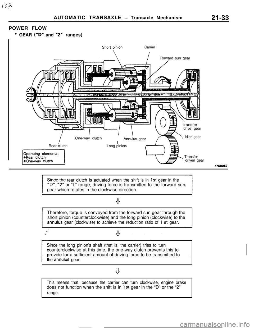
POWER FLOW
T GEAR (“D” and ‘2” ranges)
Short
DinionCarrier
IForward sun gear
IOne-way clutch
IAnn&s gear
Rear clutch
-1Long pinioniransfer
drive gear
, Idler gear
Transfer* driven gear
17!50057
rear clutch is actuated when the shift is in 1 st gear in the
“D”. “2” or “L” range, driving force is transmitted to the forward sun
gear which rotates in the clockwise direction.
ITherefore, torque is conveyed from the forward sun gear through the
short pinion (counterclockwise) and the long pinion (clockwise) to theannulus gear (clockwise) to achieve the reduction ratio of 1 st gear.
Since the long pinion’s shaft (that is, the carrier) tries to turn
/counterclockwise at this time, the one-way clutch prevents this to
provide for a sufficient amount of driving force to be transmitted to
.
the annulus gear.
,
This means that, because the carrier can turn clockwise, engine brakedoes not function when the shift is in
1 st gear in the “D” or the “2”
range.
Page 259 of 391

2ND’ GEARAUTOMATIC
TRANSAXLE - Transaxle Mechanism21-35
Kickdown brake
I
Shon pinion
\Forward sun gear
1.//LT.//. , ,’ .‘,,i.:,;:.:‘.,.‘,\/
/
Annulus gearLong pinion
Rear clutch/Reverse sun gear
fharatinn damants:
-, IWI WUIUI IWickdown brakeI
.
c
Since the rear clutch and the kickdown brake are actuated when theshift is in
2nd gear in the “0” or the “2” range, driving force is
transmitted to the forward sun gear which rotates in the clockwise
direction,
Therefore, torque is conveyed from the forward sun gear through the
short and long pinions to the annulus gear, as in the case of 1 st gear.
--However, since the reverse sun gear is fastened by in the case of
2ndgear, the long pinion“walks” on the reverse sun gear in the direction
of arrow (A), causing the annulus gear to rotate faster (or more) than
in the case of 1 st
gear in proportion to the length that the long pinionhas “walked”.
The reduction ratio of
2nd gear is achieved in this way.
---
Page 270 of 391

---21-46AUTOMATIC TRANSAXLE
- Transaxle Control
Figure A
IICITime (sec.)f
IiFigureB ,
II
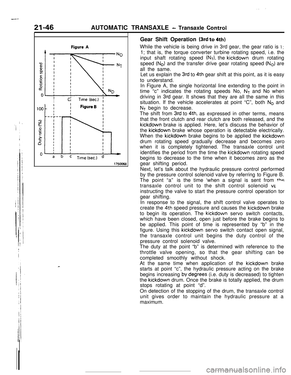
cGear Shift Operation
(3rd to 4th)While the vehicle is being drive in
3rd gear, the gear ratio is I :1; that is, the torque converter turbine rotating speed, i.e. the
input shaft rotating speed
(NT), the kickdown drum rotating
speed
(No) and the transfer drive gear rotating speed (No) are
all the same.
Let us explain the
3rd to 4th gear shift at this point, as it is easy
to understand.
In Figure A, the single horizontal line extending to the point in
time “c” indicates the rotating speeds No,
NT and No when
driving in
3rd gear. It shows that they are all the same in this
situation. If the vehicle accelerates at point “C”, both
No and
NT begin to decrease.
The shift from
3rd to 4th, as expressed in other terms, means
that the front clutch and rear clutch are both released, and thekickdown brake is applied. Here, let’s discuss the behavior of
the kickdown brake whose operation is detectable electrically.
When the kickdown brake begins to be applied the kickdown
drum rotating speed gradually decrease and becomes zero
when it is completely tightened. The transaxle control unit
identifies the period from the time the kickdown rotating speed
begins to decrease to the time when it becomes zero as the
gear shifting period.
Next, let’s talk about the hydraulic pressure control performed
by the pressure control solenoid valve by referring to Figure B.
The point “a”is the time ‘when a signal is sent from tbg
transaxle control unit to the shift control solenoid
viinstructing the valve to start the pressure control operation tor
gear shifting.
In response to the signal, the shift control valve operates to
create the 4th speed pressure and causes the kickdown brake
to begin its operation. The kickdown servo switch contacts,
which have been closed, open just before the brake begins to
be applied. This point of time is represented by “b” in the
figure. Using this kickdown servo switch contact open signal,
the transaxle control unit begins the duty control of the
pressure control solenoid valve.
The duty at the point “b” is determined with reference to the
throttle valve opening, so that the gear shifting can be
completed smoothly without shock.
At the same time when application of the kickdown brake
starts at point “c”, the hydraulic pressure acting on the brake
begins increasing by.degrees (i.e. duty is decreased) to tighten
the kickdown drum. Once the brake is totally applied, the drum
stops rotating at point “d”.
On detection of the stopping of the drum, the transaxle control
unit gives order to maintain the hydraulic pressure at a
maximum.