1990 MITSUBISHI ECLIPSE fuel pressure
[x] Cancel search: fuel pressurePage 135 of 391

‘7JFUEL SYSTEM
- Sensors14-23AIR CONDITIONER SWITCH
Batten/
-31 .,Air conditioner unitlSAO735‘Air conditioner
control unitI”.._. ,voltage
Dual pressureswitch
-f@ -//Q.j
/
Coolanttemperature6FU1148
switch
Engine control unit
3Air conditioner
This switch sends the air conditioner ON/OFF signal
to the engine control unit.
When the air conditioner is turned on and the enginecontrol unit receives the ON
signal from the switch,
it commands the idle speed control servo
toincrease the idle speed to the preset rpm. Thus
engine rpm loss due to air conditioner operation
while the engine is idling is prevented and smooth
idling operation is ensured.
Page 136 of 391

--
,
14-24FUEL SYSTEM - Sensors
POWER STEERING OIL PRESSURE SWITCHEngine control unit
Power steering oil
pressure switchBattery
voltage
6FUO5OtIWhen the steering wheel is turned and the oil
pressure of the power steering oil pump increases,
the power steering oifpressure switch sends an ON
signal to the engine control unit. The engine control
unit detects the oil pump load with this signal andactivates the idle speed control servo to control
theidle speed. Specifically, it prevents the idle
speecfrom dropping due to oil pump load, thus
ensuringstable engine idling.IGNITION
SWITCH
1IBattery
Ignition
switch
Starter motor
aS terminalcontrol unit
6FUO762The signal indicating that the ignition switch is ON,
OFF or cranking (ST) is input to the engine control
unit.
When the ignition switch ON signal is input to the
engine control unit, the unit energizes the control
relay coil to supply power to the sensors and
actuators.When the ignition switch ST signal is input to the
engine control unit, it determines that the engine
iscranking and controls the fuel injection rate,
despeed control servo, ignition timing, etc. for
-mum cranking conditions.
Page 139 of 391

‘73.- .-_ _ .-__ .- -..- - .-----___. _____^. -._ __--.
FUEL SYSTEM- Enaine Control Unit14-27
ENGINE CONTROL UNITRI4FhAA
GENERAL DESCRIPTIONEngine control unit
~
~~:~~~~~~~~~:~~
~. . . . .. .. . . . ... . . . . ... .. :+:.:.:.:.:.:.:.~.:.~+~.
6FUO76The engine control unit consists of an
8-bit micro
computer, a random access memory, a read only
memory and an input/output interface.
It determines the engine operating state based on
various information (input
signals) it receives fromthe sensors described earlier, and then controls and
activates the necessary actuators as shown in the
table below to achieve optimum engine operating
conditions.
Engine control unit
Control items
Fuel injection control
Idle speed control
Power supply control
A&;;;ditioner relay
Ignition timing control
SuTpuegohzrging control
$r;ir;;ter control
Fuel pressure control
For controlling injector driving timing
and duration based on multipoint’sequential injection.
For controlling bypass air quantity foridle speed control by activating the
idle speed control servo.
I3 Idle speed control
servo
For controlling power supply to the
sensors and actuators by controlling
the control relay.For controlling the
ON/OFF position of
the air conditioner relay.For controlling the ignition timing.
For controlling the supercharging pres-sure by regulating of the waste gate
actuator activation pressure.
For controlling the turbo meter and
displaying the supercharge pressure.
3 Ai;acenditioner
Power transistor
1
Page 141 of 391

FUEL SYSTEM- Engine Control Unit14-29
SFUllSOTerminal
ConnectionTerminalConnectionNo.
No.
1Self-diagnosis output53EGR control solenoid valve (California only)
2Diagnosis/data transfer select terminal54Power transrstor for No. 1 and No. 4 cylinder
‘3Turbo meter
55Power transistor for No. 2 and No. 3 cylinder
4Oxygen sensor56Control relay (Fuel pump control)
5Power steering oil pressure switchl 57Fuel-pressure control valve
6Idle position switch58Coil “Al ” for idle speed control servo
7Air conditioner switch59Coil “A2” for idle speed control servo
8Intake air temperature sensor60No. 3 injector
l 9Detonation sensor61No. 4 injector
10Air flow sensor62Purge control solenoid valve11
-63Control relay
12Ignition timing adjustment connector64Engine warning irght (Malfunction indicator light)
13Control relay (Fuel pump drive signal)65Air conditioner relay
l 14Air flow sensor active filter reset66Control relay
15EGR temperature sensor (California only)67Coil “Bl ” for idle speed control servo
16Barometric pressure sensor68Coil “B2” for idle speed control servo
17Sensors ground101Ground
18Vehicle speed sensor102Power supply
19Throttle position sensor103Power supply for backup
20Coolant temperature sensor
104Inhibitor switch
21Crank angle sensor‘105
Waste gate solenoid valve
22Top dead center sensor106Ground
23Power supply for sensors (5 volts)107Power supply
24Sensors ground108“ST” terminal for ignition switch
51No. 1 injector109Ignition pulse detect
52No. 2 injector170“IG ” terminal for ignition switch
NOTETerminals indicated by the l symbol are applicable only to turbo models.
Page 142 of 391

14-30SELF-DIAGNOSISFUEL SYSTEM- Engine Control Unit
There are 16 diagnosis items, as listed below; the
diagnosis results are stored in computer memory.The diagnosis memory is maintained by backup
The stored results can be ready by connecting apower from the battery (not by way of the ignition
circuit tester or voltmeter to the diagnosis
connec-switch) so that it will not be lost even if the ignition
switch is turned OFF.
tor.
DiagnosisOutput pattern
codeEl
None
lP
@ 11l-l
@ 12n@ 13
@ 14
@ 21Ul n
Diagnosis items
Faulty computer in the engine control unitMalfunction of the air/fuel ratio control system
Open or short circuit in the oxygen sensor circuit
Open or short circuit in the air flow sensor circuit
Open or short circuit in the intake air temperature sensor
circuit
Open or short circuit in the throttle position sensor circuit
Open or short circuit in the engine coolant temperature sensor
circuit
022u1 nn
No voltage change of the crank angle sensor signal
,
@
23
u u-inn
No voltage change of the TDC sensor signal
24uu-uvinnnnNo voltage change of the vehicle speed sensor signal
Q25uuuuuunnnnnOpen or short circuit in the barometric pressure sensor
2 31I-~-~---~ nOpen circuit in the detonation sensor circuit
@ 41uuul nOpen circuit in the injection circuit
042UUuLJul
Malfunction of the control relayOpen or short circuit in the fuel pump drive circuit
z 43UUULnlulMalfunction of the
EGR system
Open or short circuit in the EGR temperature sensor circuit
%4u u u uvinnOpen circuit in either of ignition coil circuit
0nNormal (with none of above faults)
. IA-r-NUltl 1:
Page 144 of 391

__.-~-..- -
FUEL SYSTEM- Ermine Control Unit
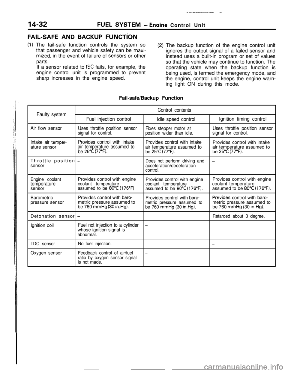
FAIL-SAFE AND BACKUP FUNCTiON
(1) The fail-safe function controls the system so
that passenger and vehicle safety can be
maxi-
mized. in the event of failure of sens.ors or other
parts.If a sensor related to
ISC fails, for example, the
engine control unit is programmed to prevent
sharp increases in the engine speed.(2) The backup function of the engine control unit
ignores the output signal of a failed sensor and
instead uses a built-in program or set of values
so that the vehicle may continue to function. The
operating state when the backup function is
being used, is termed the emergency mode, and
the engine, control unit keeps the engine warn-
ing light ON during this mode.
Fail-safe/Backup Function
Control contentsFaulty system
Fuel injection control
Idle speed controlIgnition timing control
Air flow sensor
Uses throttle position sensorFixes stepper motor atUses throttle position sensorsignal for control.
position wider than idle.signal for control.
Intake air
temper-Provides control with intake
Provides control with intakeProvides control with intake
ature sensorair temperature assumed to
be 25°C (77°F).air temperature assumed toair temperature assumed tobe 25°C (77°F).be 25°C (77°F).Throttle position
-Does not perform driving and-sensor
acceleration/deceleration
control.
Engine coolantProvides control with engine
Provides control with engineProvides control with engine
temperaturecoolant temperature
coolant temperaturecoolant temperature
sensorassumed to be 80°C (176°F)assumed to be 80°C (176°F).assumed to be 80°C (176°F).BarometricProvides control with
baro-Provides control with baro-Provides control with baro-pressure sensormetric pressure assumed to
be 760
mmHg (30 in.HgI.metric pressure assumed tometric pressure assumed tobe 760 mmHg (30 in.Hg).be 760 mmHg (30 in.Hg).Detonation sensor
-Retarded about 3 degree.Ignition coil
Fuel not injection to a cylinder-whose ignition signal is
abnormal.
TDC sensorOxygen sensor
No fuel injection.-
Feedback control of air/fuel-
ratio by oxygen sensor signal
is not made.
Page 146 of 391

-
14-34FUEL SYSTEM - Fuel Injection Control
TDC sensorAir flow sensor
I
Reading of input signal1
I ,,
uOperation mode decisionOperation mode decision data
I rBasic valve opening time data
Enginecontrol unitInjector activation time control
Injector activation pulse generationControl factor data of
engine coolant temperature,
intake air temperature and
barometric pressure, etc.
Injector1
6FUO766Needle valveFilter
Connector
Solenoid coil
Plunger
-4
INJECTOR,
The injection nozzle spray opening area is constant and the fuelinjection pressure is also constant; therefore, the injection
quantity is determined by the amount of time that the solenoid
coil is energized.
.
Page 152 of 391

14-40FUEL SYSTEM - Fuel Injection Control
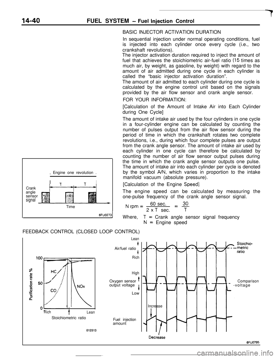
BASIC INJECTOR ACTIVATION DURATION
In sequential injection under normal operating conditions, fuel
is injected into each cylinder once every cycle (i.e., two
crankshaft revolutions).
The injector activation duration required to inject the amount of
fuel that achieves the stoichiometric air-fuel ratio
(15 times as
much air, by weight, as gasoline, by weight) with regard to the
amount of air admitted during one cycle in each cylinder is
called the “basic injector activation duration”.
The amount of air admitted to each cylinder during one cycle is
calculated by the engine control unit based on the signals
provided by the air flow sensor and crank angle sensor.
FOR YOUR INFORMATION:
Crankangle
sensor
signal, Engine one revolution .
I
TtI
t--“---t-+[Calculation of the Amount of Intake Air into Each Cylinder
during One Cycle]
The amount of intake air used by the four cylinders in one cycle
in a four-cylinder engine can be calculated by counting the
number of pulses output from the air flow sensor during the
period of time in which the crankshaft rotates two complete
revolutions, i.e., during which four complete pulses are output
from the crank angle sensor. The amount of intake air used by
each cylinder in one cycle can therefore be calculated by
counting the number of air flow sensor output pulses during
the time in which the crank angle sensor outputs one pulse.
The amount of intake air into each cylinder per cycle is denoted
by the symbol
A/N, which varies in proportion to the intake
manifold vacuum (absolute pressure).
[Calculation of the Engine
Speed]The engine speed can be calculated by measuring the
one-pulse frequency of the crank angle sensor signal.
Nrpm=60 sec.L!!L2
x T sec.TTime
6FUO27:31Where,FEEDBACK CONTROL (CLOSED LOOP CONTROL)
i
Rich1Lean
T= Crank angle sensor signal frequency
N= Engine speed
Lean
kAir/fuel ratiot
Rich
HighOxygen sensor
toutput voltage
1Low
Stoichiometric ratio
Fuel injectionamount
012513
I-
Lt
Comparison- -voltage
Increase
j/
Decriase
6FUO795