Page 129 of 228

9
General
Brake fluid type . . . . . . . . . . . . . . . . . . . . . . . . . . . . . . . . . . . . . . . . . . . . See Chapter 1
Disc brakes
Minimum brake pad thickness . . . . . . . . . . . . . . . . . . . . . . . . . . . . . . . . See Chapter 1
Brake disc minimum permissible thickness (wear limit)*
Front
3-Series
Solid discs . . . . . . . . . . . . . . . . . . . . . . . . . . . . . . . . . . . . . . . . . . 10.7 mm
Ventilated discs . . . . . . . . . . . . . . . . . . . . . . . . . . . . . . . . . . . . . . 20.0 mm
5-Series
Solid discs . . . . . . . . . . . . . . . . . . . . . . . . . . . . . . . . . . . . . . . . . . 10.0 mm
Ventilated discs . . . . . . . . . . . . . . . . . . . . . . . . . . . . . . . . . . . . . . 20.0 mm
Rear . . . . . . . . . . . . . . . . . . . . . . . . . . . . . . . . . . . . . . . . . . . . . . . . . . 8.0 mm
Brake disc minimum thickness after machining
Front
3-Series
Solid discs . . . . . . . . . . . . . . . . . . . . . . . . . . . . . . . . . . . . . . . . . . 11.1 mm
Ventilated discs . . . . . . . . . . . . . . . . . . . . . . . . . . . . . . . . . . . . . . 20.4 mm
5-Series
Solid discs . . . . . . . . . . . . . . . . . . . . . . . . . . . . . . . . . . . . . . . . . . 10.4 mm
Ventilated discs . . . . . . . . . . . . . . . . . . . . . . . . . . . . . . . . . . . . . . 20.4 mm
Rear . . . . . . . . . . . . . . . . . . . . . . . . . . . . . . . . . . . . . . . . . . . . . . . . . . 8.4 mm
Parallelism (difference between any two measurements) . . . . . . . . . . . 0.02 mm
Maximum disc run-out . . . . . . . . . . . . . . . . . . . . . . . . . . . . . . . . . . . . . . 0.2 mm
*Refer to marks cast into the disc (they supersede information printed here)
Brake pedal adjustments
Brake pedal/servo pushrod adjustment (A) (3-Series) . . . . . . . . . . . . . . 125 mm
Brake pedal height (pedal-to-bulkhead distance)
3-Series
Left-hand-drive . . . . . . . . . . . . . . . . . . . . . . . . . . . . . . . . . . . . . . . . 235 mm
Right-hand-drive . . . . . . . . . . . . . . . . . . . . . . . . . . . . . . . . . . . . . . . 273 mm
5-Series . . . . . . . . . . . . . . . . . . . . . . . . . . . . . . . . . . . . . . . . . . . . . . . . 245 mm
Stop-light switch adjustment (dimension A - see text) . . . . . . . . . . . . . . 5.0 mm to 6.0 mm
Handbrake
Handbrake shoe lining minimum thickness . . . . . . . . . . . . . . . . . . . . . . 1.5 mm
Handbrake lever travel . . . . . . . . . . . . . . . . . . . . . . . . . . . . . . . . . . . . . . 5 to 8 clicks
Chapter 9 Braking system
Anti-lock brake system (ABS) - general information . . . . . . . . . . . . . 2
Brake check . . . . . . . . . . . . . . . . . . . . . . . . . . . . . . . . See Chapter 1
Brake disc - inspection, removal and refitting . . . . . . . . . . . . . . . . . 5
Brake fluid level check . . . . . . . . . . . . . . . . . . . . . . . . See Chapter 1
Brake hoses and lines - inspection and renewal . . . . . . . . . . . . . . . . 15
Brake hydraulic system - bleeding . . . . . . . . . . . . . . . . . . . . . . . . . . 16
Brake pedal - adjustment . . . . . . . . . . . . . . . . . . . . . . . . . . . . . . . . . 13
Brake vacuum servo - check, removal and refitting . . . . . . . . . . . . . 8
Disc brake caliper - removal, overhaul and refitting . . . . . . . . . . . . . 4Disc brake pads - renewal . . . . . . . . . . . . . . . . . . . . . . . . . . . . . . . . 3
Drum brake shoes - renewal . . . . . . . . . . . . . . . . . . . . . . . . . . . . . . . 6
General information . . . . . . . . . . . . . . . . . . . . . . . . . . . . . . . . . . . . . . 1
Handbrake assembly - check, removal and refitting . . . . . . . . . . . . 12
Handbrake - adjustment . . . . . . . . . . . . . . . . . . . . . . . . . . . . . . . . . . 11
Handbrake cable(s) - renewal . . . . . . . . . . . . . . . . . . . . . . . . . . . . . . 10
Hydraulic brake servo - description, removal and refitting . . . . . . . . 9
Master cylinder - removal and refitting . . . . . . . . . . . . . . . . . . . . . . . 7
Stop-light switch - check and adjustment . . . . . . . . . . . . . . . . . . . . 14
9•1
Easy,suitable for
novice with little
experienceFairly easy,suitable
for beginner with
some experienceFairly difficult,
suitable for competent
DIY mechanic
Difficult,suitable for
experienced DIY
mechanicVery difficult,
suitable for expert
DIY or professional
Degrees of difficulty
Specifications Contents
Page 130 of 228
 bolts . . . . . . . . . . . . . . . . . . . . . . . . . . . . . . 30 to 35
Caliper bracket-to-strut housing bolts
3-Series,")
Torque wrench settingsNm
Front disc brake caliper
Caliper guide (mounting) bolts . . . . . . . . . . . . . . . . . . . . . . . . . . . . . . 30 to 35
Caliper bracket-to-strut housing bolts
3-Series, E30 . . . . . . . . . . . . . . . . . . . . . . . . . . . . . . . . . . . . . . . . . . 123
5-Series, E28 (“old-shape”) . . . . . . . . . . . . . . . . . . . . . . . . . . . . . . . 123
5-Series, E34 (“new-shape”) . . . . . . . . . . . . . . . . . . . . . . . . . . . . . . 110
Rear disc brake caliper
Caliper guide (mounting) bolts . . . . . . . . . . . . . . . . . . . . . . . . . . . . . . 30 to 35
Carrier-to-trailing arm bolts . . . . . . . . . . . . . . . . . . . . . . . . . . . . . . . . 67
Brake hose-to-caliper fitting . . . . . . . . . . . . . . . . . . . . . . . . . . . . . . . . . . 14 to 17
Master cylinder-to-brake servo nuts
3-Series . . . . . . . . . . . . . . . . . . . . . . . . . . . . . . . . . . . . . . . . . . . . . . . . 24
5-Series . . . . . . . . . . . . . . . . . . . . . . . . . . . . . . . . . . . . . . . . . . . . . . . . 25 to 29
Brake servo mounting nuts . . . . . . . . . . . . . . . . . . . . . . . . . . . . . . . . . . . 22 to 24
Hydraulic line-to-hydraulic brake servo threaded
fittings - 5-Series, E28 (“old-shape”) . . . . . . . . . . . . . . . . . . . . . . . . . . . 31
Wheel bolts . . . . . . . . . . . . . . . . . . . . . . . . . . . . . . . . . . . . . . . . . . . . . . . See Chapter 1
9•2 Braking system
1 General information
All 3-Series models, and 5-Series E28 (“old-
shape”) models, are equipped with front disc
brakes and either rear drum or rear disc
brakes. 5-Series E34 (“new-shape”) models
have disc brakes front and rear. Front and
rear brakes are self-adjusting on all models.
Some later models are equipped with an Anti-
lock Braking System (ABS); this is described
in Section 2.
Hydraulic system
The hydraulic system consists of two
separate circuits. The master cylinder has
separate reservoirs for the two circuits; in the
event of a leak or failure in one hydraulic
circuit, the other circuit will remain operative.
Brake servo
The vacuum brake servo, utilising engine
manifold vacuum and atmospheric pressure
to provide assistance to the hydraulically
operated brakes, is mounted on the bulkhead
in the engine compartment.
A hydraulic brake servo system is used on
5-Series E28 models. This system uses
hydraulic pressure from the power steering
pump to assist braking.
Handbrake
The handbrake operates the rear brakes,
and is cable-operated via a lever mounted in
the centre console. The handbrake assembly
on rear drum brake models is part of the rear
drum brake assembly, and is self-adjusting.
On rear disc brake models, the handbrake
uses a pair of brake shoes located inside the
centre portion of the rear brake disc, and is
manually-adjusted.
Brake pad wear warning system
The brake pad wear warning system is
linked to a red warning light in the instrumentcluster, which comes on when the brake pads
have worn down to the point at which they
require renewal. DO NOT ignore this reminder.
If you don’t renew the pads shortly after the
brake pad wear warning light comes on, the
brake discs will be damaged.
On some models, the brake pad wear
warning system also includes an early
warning light that comes on only when the
brake pedal is depressed, letting you know in
advance that the pads need to be renewed.
The wear sensor is attached to the brake
pads. The sensor is located at the left front
wheel; on some models, there is another
sensor at the right rear wheel. The wear
sensor is part of a closed circuit. Once the
pads wear down to the point at which they’re
flush with the sensor, the disc grinds away the
side of the sensor facing the disc. Thus, the
wire inside the sensor is broken, and the red
light on the instrument panel comes on.
Always check the sensor(s) when renewing
the pads. If you change the pads before the
warning light comes on, the sensor(s) may still
be good; once the light has come on, renew
the sensor.
Service
After completing any operation involving
dismantling of any part of the brake system,
always test drive the vehicle to check for
proper braking performance before resuming
normal driving. When testing the brakes, try to
select a clean, dry, road with no camber (ie as
flat as possible) and with no other traffic.
Conditions other than these can lead to
inaccurate test results.
Test the brakes at various speeds with both
light and heavy pedal pressure. The vehicle
should stop evenly, without pulling to one side
or the other. Avoid locking the brakes,
because this slides the tyres and diminishes
braking efficiency and control of the vehicle.
Tyres, vehicle load and wheel alignment are
factors which also affect braking
performance.
2 Anti-lock Braking system
(ABS)- general information
The Anti-lock Braking System is designed
to maintain vehicle control, directional stability
and optimum deceleration under severe
braking conditions on most road surfaces. It
does so by monitoring the rotational speed of
each wheel and controlling the brake line
pressure to each wheel during braking. This
prevents the wheels from locking up.
The ABS system has three main
components - the wheel speed sensors, the
electronic control unit, and the hydraulic
control unit. The sensors - one at each wheel
since 1985, but at both front wheels and one
at the rear differential on earlier models - send
a variable voltage signal to the control unit,
which monitors these signals, compares them
to its program information, and determines
whether a wheel is about to lock up. When a
wheel is about to lock up, the control unit
signals the hydraulic unit to reduce hydraulic
pressure (or not increase it further) at that
wheel’s brake caliper. Pressure modulation is
handled by electrically-operated solenoid
valves.
If a problem develops within the system, an
“ABS” warning light will glow on the
dashboard. Sometimes, a visual inspection of
the ABS system can help you locate the
problem. Carefully inspect the ABS wiring
harness. Pay particularly close attention to the
harness and connections near each wheel.
Look for signs of chafing and other damage
caused by incorrectly-routed wires. If a wheel
sensor harness is damaged, the sensor
should be renewed (the harness and sensor
are integral).
Warning: DO NOT try to repair an
ABS wiring harness. The ABS
system is sensitive to even the
smallest changes in resistance. Repairing
the harness could alter resistance values
Page 131 of 228

and cause the system to malfunction. If
the ABS wiring harness is damaged in any
way, it must be renewed.
Caution: Make sure the ignition is
turned off before unplugging or
re-making any electrical
connections.
Diagnosis and repair
If the dashboard warning light comes on
and stays on while the vehicle is in operation,
the ABS system requires attention. Although
special electronic ABS diagnostic testing
tools are necessary to properly diagnose the
system, you can perform a few preliminary
checks before taking the vehicle to a dealer
service department.
a) Check the brake fluid level in the
reservoir.
b) Verify that the electronic control unit
connectors are securely connected.
c) Check the electrical connectors at the
hydraulic control unit.
d) Check the fuses.
e) Follow the wiring harness to each front
and rear wheel, and verify that all
connections are secure and that the
wiring is undamaged.
If the above preliminary checks do not
rectify the problem, the vehicle should bediagnosed by a dealer service department.
Due to the complex nature of this system, all
actual repair work must be done by a dealer
service department.
3 Disc brake pads- renewal
2
Warning: Disc brake pads must
be renewed on both front wheels
or both rear wheels at the same
time - NEVER renew the pads on
only one wheel. Also, the dust created by
the brake system may contain asbestos,
which is harmful to your health. Never
blow it out with compressed air, and don’t
inhale any of it. An approved filtering mask
should be worn when working on the
brakes. Do not, under any circumstances,
use petroleum-based solvents to clean
brake parts. Use brake system cleaner
only! When servicing the disc brakes, use
only original-equipment or high-quality
brand-name pads.
Warning: Brake fluid is
poisonous. It is also an effective
paint stripper. Refer to the
warning at the start of Section 16.
Note:This procedure applies to both the front
and rear disc brakes.
1Remove the cap(s) from the brake fluid
reservoir, and syphon off about two-thirds of
the fluid from the reservoir. Failing to do thiscould result in the reservoir overflowing when
the caliper pistons are pressed back into their
bores.
2Loosen the wheel bolts, raise the front or
rear of the vehicle and support it securely on
axle stands.
3Remove the front or rear wheels, as
applicable. Work on one brake assembly at a
time, using the assembled brake for reference
if necessary.
4Inspect the brake disc carefully as outlined
in Section 5. If machining is necessary, follow
the information in that Section to remove the
disc, at which time the pads can be removed
from the calipers as well.
5Follow the accompanying photos,
beginning with illustration 3.5a, for the pad
removal procedure. Be sure to stay in order,
and read the caption under each illustration.
Note 1:Different types of front calipers are
used on 3 and 5-Series models. Illustrations
3.5a to 3.5e are for the front calipers on 3-
Series models.Illustrations 3.5f to 3.5m are
for the front calipers on 5-Series models.
There’s no photo sequence for rear calipers;
although slightly different in size, they’re
identical in design to the front brake calipers
used on 5-Series models.Note 2: Some
models may have different numbers and types
of anti-squeal shims and other hardware than
what is shown in this Chapter. It’s best to note
how the hardware is fitted on the vehicle
before dismantling, so you can duplicate it on
reassembly.
Braking system 9•3
3.5c Hold the guide pins while loosening
the caliper mounting bolts (3-Series)3.5b Unplug the electrical connector for
the brake pad wear sensor (3-Series)
3.5a On 3-Series models, unscrew the
caliper mounting bolts (left arrows); right
arrows point to the caliper bracket bolts,
which should only be removed if you’re
removing the brake disc
3.5f On 5-Series models, unplug the
electrical connector for the brake pad
wear sensor3.5e Remove the outer brake pad
(3-Series) - to fit the new pads, reverse the
removal procedure
3.5d Remove the caliper, brake pad wear
sensor and inner pad all at the same time
(3-Series), then refit the inner pad on the
piston and press the piston fully into the
bore with a C-clamp
9
Page 132 of 228
 (left
front wheel only, or left front and right rear
wheel). If they’re OK, transfer them from the
old pads to the new ones; if they’re worn by
abrasion, fit")
6Be sure to inspect the wear sensor(s) (left
front wheel only, or left front and right rear
wheel). If they’re OK, transfer them from the
old pads to the new ones; if they’re worn by
abrasion, fit new sensors on the new pads.
7To fit the new pads, reverse the removal
procedure. When refitting the caliper, be sure
to tighten the mounting bolts to the torque
listed in this Chapter’s Specifications.
Warning: Check and if necessary
renew the mounting bolts on 3-
Series models whenever they are
removed. If in doubt, use new
bolts.
8After the job is completed, firmly depress
the brake pedal a few times, to bring the pads
into contact with the discs. The pedal shouldbe at normal height above the floor, and firm.
Check the level of the brake fluid, adding
some if necessary. Check carefully for leaks,
and check the operation of the brakes before
returning the vehicle to normal service.
9Avoid heavy braking as far as possible for
the first hundred miles or so until the new
pads have bedded in.
4 Disc brake caliper- removal,
overhaul and refitting
4
Warning: Dust created by the
brake system may contain
asbestos, which is harmful to
your health. Never blow it out
with compressed air, and don’t inhale any
of it. An approved filtering mask should be
worn when working on the brakes. Do not,
under any circumstances, use petroleum-
based solvents to clean brake parts. Use
brake system cleaner only!
Warning: Brake fluid is
poisonous. It is also an effective
paint stripper. Refer to the
warning at the start of Section 16.
Note:If an overhaul is indicated (usually
because of fluid leakage), explore all options
before beginning the job. Overhauled calipers
may be available on an exchange basis, which
makes this job quite easy. If you decide to
overhaul the calipers, make sure that anoverhaul kit is available before proceeding.
Always overhaul the calipers in pairs - never
overhaul just one of them.
Removal
1Loosen the wheel bolts, raise the front or
rear of the vehicle, and place it securely on
axle stands. Remove the wheel.
2If you’re just removing the caliper for
access to other components, it isn’t
necessary to detach the brake line. If you’re
removing the caliper for overhaul, disconnect
the brake line from the caliper, for preference
using a split ring (“brake”) spanner to protect
the fitting. Plug the line, to keep contaminants
out of the brake system and to prevent losing
brake fluid unnecessarily.
3Refer to Section 3 for the front or rear
caliper removal procedure - it’s part of the
brake pad renewal procedure. Note:The rear
caliper is similar in design to the front caliper
on 5-series models.
Overhaul
4On all calipers except the front calipers on
3-Series models, remove the circlip for the
dust seal (see illustration),then remove the
dust boot (see illustration). Before you
remove the piston, place a block of wood
between the piston and caliper to prevent
damage as it is removed.
5To remove the piston from the caliper,
apply compressed air to the brake fluid hose
connection on the caliper body (see
9•4 Braking system
3.5l Hang the caliper out of the way with a
piece of wire
3.5m Remove the outer brake pad - to fit
the new pads, reverse the removal
procedure
3.5k Unclip the inner brake pad from the
piston (5-Series)3.5j Remove the caliper and inner brake
pad (5-Series)
3.5i Depress the piston with a C-clamp
(5-Series)3.5h Prise off the anti-rattle spring
(5-Series)3.5g Remove the plugs for the brake
caliper mounting bolts, then remove the
bolts (5-Series)
Page 133 of 228
. Use only low pressure, such as
that produced by a foot pump, to ease the
piston out of its bore.
Warning: Be careful not to place
your fingers between the piston
and the caliper, as the")
illustration). Use only low pressure, such as
that produced by a foot pump, to ease the
piston out of its bore.
Warning: Be careful not to place
your fingers between the piston
and the caliper, as the piston
may come out with some force. If
you’re working on a front caliper of a 3-
Series model, remove the dust boot.
6Inspect the mating surfaces of the piston
and caliper bore wall. If there is any scoring,
rust, pitting or bright areas, renew the
complete caliper unit.
7If these components are in good condition,
remove the piston seal from the caliper bore
using a wooden or plastic tool (see
illustration). Metal tools may damage the
cylinder bore.
8Remove the caliper guide pins or bolts and
remove the rubber dust boots.
9Wash all the components using methylated
spirit or brake system cleaner.
10Using the correct overhaul kit for your
vehicle, reassemble the caliper as follows.
11Dip the new rubber seal in clean brake
fluid, and refit it in the lower groove in the
caliper bore, making sure it isn’t twisted.
12On all calipers except the front calipers of
3-Series models, coat the walls of the caliperbore and the piston with clean brake fluid, and
refit the piston at this time. Do not force the
piston into the bore, but make sure that it is
squarely in place, then apply firm (but not
excessive) pressure to refit it. Fit the new
rubber dust boot and the retaining ring.
13On the front calipers of 3-Series models,
coat the piston with clean brake fluid, and
stretch the new dust boot over the bottom of
the piston. Hold the piston over the caliper
bore, and insert the rubber flange of the dust
boot into the upper groove in the bore. Start
with the furthest side from you, and work your
way around towards the front until it is
completely seated. Push the piston into the
caliper bore until it is bottomed in the bore,
then seat the top of the dust boot in the
groove in the piston.
14Lubricate the sliding surfaces of the guide
pins or bolts with silicone-based grease
(usually supplied in the kit), and push them
into the caliper. Refit the dust boots.
Refitting
15Refit the caliper by reversing the removal
procedure (see Section 3).
Warning: Check and if necessary
renew the mounting bolts on 3-
Series models whenever they are
removed. If in doubt, use new bolts.16If the hose was disconnected from the
caliper, bleed the brake system (see Sec-
tion 16).
5 Brake disc- inspection,
removal and refitting
2
Note:This procedure applies to both the front
and rear brake discs. Brake discs should
always be renewed or refinished in pairs (both
front or both rear discs) even if only one is
damaged or defective.
Braking system 9•5
4.4b Remove the circlip for the dust seal
4.4a An exploded view of a typical rear caliper assembly (front calipers similar)
4.7 Remove the piston seal from the
caliper bore using a wooden or plastic tool
(metal tools may damage the
cylinder bore)
1 Caliper assembly
2 Bracket mounting bolt
3 Bleed screw
4 Dust cap
5 Anti-rattle spring
6 Guide bolt
7 Brake pad wear warning
light wire8 Cable clamp
9 Brake disc
10 Allen bolt
11 Shield
12 Bolt
13 Washer
14 Plug15 Plug
16 Caliper bracket
17 Cable clamp
18 Piston seal, piston, dust
boot and circlip
19 Guide bush repair kit
20 Brake pads4.5 With the caliper padded to catch the
piston, use low pressure compressed air
to force the piston out of its bore - make
sure your fingers are not between the
piston and the caliper
9
Page 134 of 228

Inspection
1Loosen the wheel bolts, raise the vehicle
and support it securely on axle stands.
Remove the wheel, and refit three bolts to
hold the disc in place. If the rear brake disc is
being worked on, release the handbrake.
2Remove the brake caliper as outlined in
Section 4. It is not necessary to disconnect
the brake hose. After removing the caliper,
suspend it out of the way with a piece of wire.
Remove the caliper mounting bracket (see
illustration).
3Inspect the disc surface for scoring, cracks
or other damage. Light scratches and shallow
grooves are normal after use, and are not
usually detrimental to brake operation, but
deep scoring requires disc removal andrenewal, or (if possible) refinishing by a
specialist. If a disc is cracked it must be
renewed. Be sure to check both sides of the
disc (see illustration). If severe vibration has
been noticed during application of the brakes,
the discs may be warped (excessive run-out).
If the vehicle is equipped with the Anti-lock
Braking System (ABS), do not confuse
vibration caused by warped discs with normal
operation of the ABS. It is quite normal for
some vibration to be felt through the pedal
when the system is working.
4To check disc run-out, place a dial indicator
at a point about 13 mm from the outer edge of
the disc (see illustration). Set the indicator to
zero, and rotate the disc. The indicator
reading should not exceed the specifiedallowable run-out limit. If it does (and if the
run-out is not due to wheel bearing wear), the
disc should be renewed or (if possible)
refinished by a specialist. Note:It is
recommended that the discs be resurfaced
regardless of the dial indicator reading, as this
will impart a smooth finish and ensure a
perfectly flat surface, eliminating any vibration
felt through the brake pedal or other
undesirable symptoms related to questionable
discs. At the very least, if you elect not to have
the discs resurfaced, remove the glazing from
the surface with emery cloth or sandpaper,
using a swirling motion (see illustration).
5It is absolutely critical that the disc not be
machined to a thickness less than that
specified. The minimum wear (or discard)
thickness is stamped into the hub of the disc.
The disc thickness can be checked with a
micrometer (see illustration).
Removal
6Remove the disc retaining screw (see
illustration) and remove the disc from the hub
(see illustration). If the disc is stuck to the
hub, spray a generous amount of penetrating
oil onto the area between the hub and the disc
(see illustration)and allow a few minutes for
it to loosen the rust between the two
components. If a rear disc still sticks, insert a
thin, flat-bladed screwdriver through the hub
flange, rotate the starwheel on the handbrake
9•6 Braking system
5.6c If the disc is stuck to the hub, spray
some penetrating oil onto the area
between the hub and the disc, and give the
oil a few minutes to separate the two parts
5.6b . . . and remove the disc from
the hub5.6a Remove the disc retaining screw . . .
5.5 The disc thickness can be checked
with a micrometer5.4b Using a swirling motion, remove the
glaze from the disc surface with
sandpaper or emery cloth
5.4a To check disc run-out, mount a dial
indicator as shown, and rotate the disc5.3 The brake pads on this vehicle were
obviously neglected, as the backing plate
cut deep grooves into the disc - wear this
severe means the disc must be renewed5.2 Remove the caliper mounting bracket
bolts (arrowed) and remove the bracket
Page 135 of 228
.
Refitting
7Ensure that the disc is completely clean
before refitting. If penetrating oil was used to
remove the disc, make sure tha")
adjusting screw and contract the handbrake
shoes (see illustration).
Refitting
7Ensure that the disc is completely clean
before refitting. If penetrating oil was used to
remove the disc, make sure that no trace of
this is present. Place the disc on the hub, and
refit the disc retaining screw. Tighten the
screw securely.
8Refit the caliper mounting bracket (if
removed), brake pads and caliper (see
Sections 3 and 4). Tighten all fasteners to the
torques listed in this Chapter’s Specifications.
9Refit the wheel, then lower the vehicle to
the ground. Depress the brake pedal a few
times to bring the brake pads into contact
with the disc.
10Adjust the handbrake shoes, if necessary
(Section 11).
11Check the operation of the brakes
carefully before returning the vehicle to
normal service.
6 Drum brake shoes- renewal
2
Warning: Brake shoes must be
renewed on both wheels at the
same time - never renew the
shoes on only one wheel. Also,
the dust created by the brake system may
contain asbestos, which is harmful to your
health. Never blow it out with compressed
air, and don’t inhale any of it. Always wear
an approved filtering mask when servicing
the brake system. Do not, under anycircumstances, use petroleum-based
solvents to clean brake parts. Use brake
system cleaner only.
Caution: Whenever the brake
shoes are renewed, new return
and hold-down springs and new
automatic adjuster thermo-clips
should also be fitted. Due to the
continuous heating/cooling cycle to which
the springs are subjected, they may lose
their tension over a period of time,
allowing the shoes to drag on the drum,
and wear at a much faster rate than
normal. When fitting new brake shoes, use
only original-equipment or high-quality
brand name parts.
Note 1:All four rear brake shoes must be
renewed at the same time, but to avoid mixing
up parts, work on only one brake assembly at
a time. Some rear brake components are
different for left and right-hand sides, so don’t
mix them up.
Note 2:If the wheel cylinder is found to be
leaking or otherwise defective, renew it after
removing the brake shoes. This is simply a
matter of disconnecting the hydraulic line and
unbolting the cylinder from the backplate.
Attempting to overhaul a leaking cylinder is
unlikely to be satisfactory, even if spare parts
are available.
1Chock the front wheels, then loosen the
rear wheel bolts, raise the rear of the vehicle
and place it securely on axle stands. Remove
the rear wheels and release the handbrake.
2Remove the drum retaining screw (see
illustration)and remove the drum. If the drum
is stuck to the hub, spray the area between
the hub and the drum with penetrating oil
(see illustration). If the drum still won’t come
off, the shoes have probably worn ridges into
the drum, and will have to be retracted. Insert
a narrow flat-bladed screwdriver through one
of the holes in the hub flange (see
illustration)and back off the adjuster wheel
until the drum can be removed.
3Inspect the drum for cracks, score marks,
deep scratches and hard spots, which will
appear as small discoloured areas. If the hard
spots can’t be removed with emery cloth or if
any of the other conditions exist, the drum must
be taken to a specialist to have the drum
resurfaced. Note:Professionals recommendresurfacing the drums whenever a brake job is
done. Resurfacing will eliminate the possibility
of out-of-round drums. If the drums are worn so
much that they can’t be resurfaced without
exceeding the maximum allowable diameter
(which is cast into the drum) (see illustration),
then new ones will be required. At the very least,
if you elect not to have the drums resurfaced,
remove the glazing from the surface with emery
cloth or sandpaper, using a swirling motion.
Braking system 9•7
6.2b If the drum is stuck to the hub, apply
penetrating oil around the hub/drum area,
and give it a few minutes to loosen up
any rust6.2a Removing the drum retaining screw5.6d If a rear disc still sticks to the hub,
insert a thin, flat-bladed screwdriver
through the hub flange, rotate the
starwheel on the handbrake adjusting
screw, and contract the handbrake shoes
(disc removed for clarity)
6.3 The maximum allowable inside
diameter of the drum is cast into the drum
6.2c If the brake shoes have worn a
groove in the drum and it won’t come off,
insert a thin flat-bladed screwdriver
through one of the wheel bolt holes in the
flange, and loosen the automatic adjuster
mechanism (for the sake of clarity, the
drum has already been removed in this
photo, and the screwdriver is being
inserted underneath the flange instead of
though a wheel bolt hole)
9
If the front disc is stuck, on
some discs it is possible to
thread two or three bolts into
the holes provided and
tighten them. Alternate between the
bolts, turning them a couple of turns at
a time, until the disc is free.
Page 136 of 228
.
5Unhook and remove the upper return spring
(see illustrations).
6Remove the front and rear brake shoe hold-
down springs (see illustrati")
4Unhook and remove the lower return spring
(see illustrations).
5Unhook and remove the upper return spring
(see illustrations).
6Remove the front and rear brake shoe hold-
down springs (see illustrations).
7Remove the front shoe (see illustration).
8Remove the adjuster assembly (see
illustration). Clean the adjuster and make
sure that the adjuster wheel moves freely on
the threads. It is recommended that the
thermo-clip (the spring clip next to theadjuster wheel) be renewed whenever new
shoes are fitted. Turn the adjuster wheel so
that the assembly is at its shortest position
ready for refitting.
9Disconnect the handbrake cable from the
handbrake lever, and remove the rear shoe
(see illustration).
10Refitting is basically the reverse of
removal, but note the following points.
11Apply a smear of high-temperature brake
grease to the backing plate (see illustration).
Be careful not to get grease onto the
9•8 Braking system
6.11 Before you fit the new shoes, apply
some high-temperature brake grease to
the friction surfaces where the inner edge
of the shoe slides on the brake backing
plate - when you refit the automatic
adjuster mechanism, make sure each end
engages properly with its respective notch
in the brake shoe6.9 To disconnect the handbrake cable
from the handbrake lever, pull on the plug
at the end of the cable, and detach the
cable from the bracket on the upper end of
the lever (diagonal cutting pliers are being
used here because they grip the cable
well, but care must be taken not to nick
the cable)
6.8 Remove the automatic adjuster
assembly
6.7 Remove the front shoe, automatic
adjuster lever and spring as an assembly,
then remove the lever and spring, and set
them aside for attachment to the new shoe
6.6b . . . and the rear shoe hold-
down spring6.6a Remove the front shoe hold-
down spring . . .6.5b . . . then unhook it from the rear shoe
and remove it
6.5a Unhook the upper return spring from
the front shoe . . .6.4b . . . then unhook it from the rear shoe
and remove it6.4a Unhook the lower return spring from
the front shoe . . .
 1
1 2
2 3
3 4
4 5
5 6
6 7
7 8
8 9
9 10
10 11
11 12
12 13
13 14
14 15
15 16
16 17
17 18
18 19
19 20
20 21
21 22
22 23
23 24
24 25
25 26
26 27
27 28
28 29
29 30
30 31
31 32
32 33
33 34
34 35
35 36
36 37
37 38
38 39
39 40
40 41
41 42
42 43
43 44
44 45
45 46
46 47
47 48
48 49
49 50
50 51
51 52
52 53
53 54
54 55
55 56
56 57
57 58
58 59
59 60
60 61
61 62
62 63
63 64
64 65
65 66
66 67
67 68
68 69
69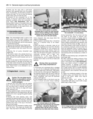 70
70 71
71 72
72 73
73 74
74 75
75 76
76 77
77 78
78 79
79 80
80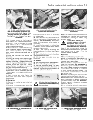 81
81 82
82 83
83 84
84 85
85 86
86 87
87 88
88 89
89 90
90 91
91 92
92 93
93 94
94 95
95 96
96 97
97 98
98 99
99 100
100 101
101 102
102 103
103 104
104 105
105 106
106 107
107 108
108 109
109 110
110 111
111 112
112 113
113 114
114 115
115 116
116 117
117 118
118 119
119 120
120 121
121 122
122 123
123 124
124 125
125 126
126 127
127 128
128 129
129 130
130 131
131 132
132 133
133 134
134 135
135 136
136 137
137 138
138 139
139 140
140 141
141 142
142 143
143 144
144 145
145 146
146 147
147 148
148 149
149 150
150 151
151 152
152 153
153 154
154 155
155 156
156 157
157 158
158 159
159 160
160 161
161 162
162 163
163 164
164 165
165 166
166 167
167 168
168 169
169 170
170 171
171 172
172 173
173 174
174 175
175 176
176 177
177 178
178 179
179 180
180 181
181 182
182 183
183 184
184 185
185 186
186 187
187 188
188 189
189 190
190 191
191 192
192 193
193 194
194 195
195 196
196 197
197 198
198 199
199 200
200 201
201 202
202 203
203 204
204 205
205 206
206 207
207 208
208 209
209 210
210 211
211 212
212 213
213 214
214 215
215 216
216 217
217 218
218 219
219 220
220 221
221 222
222 223
223 224
224 225
225 226
226 227
227