1989 MAZDA 323 fuel cap
[x] Cancel search: fuel capPage 20 of 1164

PRE-DELIVERY INSPECTION
PRE-DELIVERY INSPECTION
PRE-DELIVERY INSPECTION TABLE
Following items may be done at any time prior to delivery to your customer.
INSPECT and ADJUST, if necessary, the following items to
the specifications:
0 Glass, exterior bright metal and paint for damage
Cl Wheel lug nuts, and locks (if equipped)
88-118 N.m (9-12 m-kg, 65-87 ft-lb)
q All weatherstrips for damage or detachment
0 Operation of hood release and lock
0 Operation of trunk lid, rear hatch, and fuel lid opener
Cl With trunk open, check for spare jack, tire, tools, and
fasteners securing these items in place.
Cl Door operation and alignment
Cl Headlight aim
INSTALL the following parts:
Cl Wheel caps or rings (if equipped)
q Outside rearview mirror(s)
1 UNDER HOOD-ENGINE OFF )
INSPECT and ADJUST, if necessary, the following items to
the specifications:
0 Fuel, coolant and hydraulic lines, fittings, connections and
components for leaks
Cl Engine oil level
0 Power steering fluid level
0 Brake and clutch master cylinder fluid level
El Windshield washer reservoir fluid level
Cl Radiator coolant level
Cl Tightness of battery terminals
Cl Manual transaxle oil level
riizmiq
INSTALL the following parts:
Cl Rubber stopper for inside rearview mirror
CHECK operation of the following items:
0 Seat controls (sliding and reclining) and head restraint
Cl Folding rear seat
0 Door locks, including childproof door locks (if equipped)
Seat belts and warning system
Cl Ignition switch and steering lock
0 Inhibitor switch (ATX only)
U Starter interlock switch (clutch pedal, MTX only)
Cl All lights, including warning and indicator lamps
Cl Sound warning system
Cl Horn, wipers and washers (front and rear, if equipped)
0 Audio system (if equipped) 0 Cigarette lighter and clock
0 Sunroof (if equipped)
II Remote control outside rearview mirrors (if equipped)
Cl Power windows (if equipped)
q Heater, defroster and air conditioner at various mode
selections (if equipped)
CHECK the following items:
Cl Presence of spare fuse
0 Upholstery and interior finish
CHECK and ADJUST, if necessary, the following items:
0 Pedal height and free play of brake and clutch pedal
Pedal height mm (in) Free play mm (in)
0 Parking brake
5-7 notches/98 N (10 kg, 22lb)
UNDER HOOD-ENGINE RUNNING AT
OPERATING TEMPERATURE
CHECK the following items:
q Automatic transaxle fluid level
[I
CHECK the following items:
Cl Underside fuel, coolant and hydraulic lines, fittings, con-
nections and components for leaks
0 Tires for cuts or bruises
0 Steering linkage, suspension, exhaust system and all un-
derside hardware for looseness or damage
[I
CHECK the following items:
0 Brake operation
0 Clutch operation
Cl Steering control
Cl Operation of gauges
q Squeaks, rattles or unusual noise
Cl Emergency locking retractors
0 Cruise control system (if equipped)
1 AFTER ROAD TEST (
CHECK for necessary owner information materials.
Following items must be done just before the delivery to your customer.
q Load test battery and charge if necessary
1 Volts 1 0 Install fuses for accessories
i.. _
0 Adjust tire pressure to the specification
Load test result cl Remove seat and floor mat protective covers
(Refer to door label) 0 Vacuum and clean interior of vehicle
0 Clean outside of vehicle q Inspect installation of option parts with invoice
23UOAX-002
A-2
Page 22 of 1164

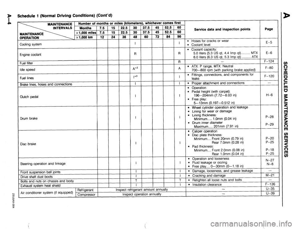
7 Schedule 1 (Normal Driving Conditions) (Cont’d)
MAINTENANCE
INTERVALS 1 ::::“’ rths ’ 7.5
DPERATION x 1,000 miles
x 1,000 km 3r mi
15
15
24
1
Page
l- . whichever comes first s (kilometer!
37.5
37.5
60 52.5
52.5
64 60
60
96
I
l-7
Service data and inspection points
l Hoses for cracks or wear l Coolant level E-5
Zooling system
Engine coolant
Fuel filter
‘die speed
Fuel lines
Brake lines, hoses and connections
l Coolant capacity:
5.0 liters (5.3 US qt, 4.4 Imp qt) . . . . . . . . . . MTX
6.0 liters (6.3 US qt, 5.3 Imp qt) . . . . . . . . . . ATX
I E-6 -
F-l 24
l ATX: P range, MTX: Neutral
700-800 rpm (with parking brake applied)
l Fittings, connections, and components for F-80
F-120
-
H-6
P-28
P-29
P-20
P-25
P-18
P-25
---
N-27
N-8
-
M-21
-
F-136
u-35
u-39 leaks
0 Proper attachment and connections
l Operation l Pedal height (with carpet):
196-204mm (7.72-8.03 in)
l Free play:
5--13mm 10.197-0.512 in) Clutch pedal
l Wheel cylinder operation and leakage
l Lining for wear or damage l Lining thickness:
Minimum . . . . . 1 .Omm (0.04 in)
l Drum inner diameter
Maximum..... 201mm (7.91 in) Drum brake
l Caliper operation l Disc plate thickness:
Minimum.... Front 20mm (0.79 in)
Rear 7.0mm (0.28 in)
l Pad thickness:
Minimum.... Front 2.0mm (0.08 in)
Rear l.Omm (0.04 in)
l Operation and looseness l Fluid leakage or oozing l Free play.... O-30mm (O-l .18 in)
l Damage, looseness, and grease leakage
l Cracking and damage
l Retighten all loose nuts and bolts I
1
Disc brake
I
---l-T
Steering operation and linkage
Front suspension ball joints
Drive shaft dust boots
Bolts and nuts on chassis and body
Exhaust system heat shield
Air conditioner system (if equipped) Refrigerant
Compressor am01 anni I
l Insulation clearance
- ,.
Inspect rerrlgerar
Inspect operation annually -
Page 24 of 1164

y Schedule 2 (Unique Driving Conditions)
OPERATION
Drive belts MAINTENANCE / Number of months or miles (kilometers), whichever comes first
INTERVALS Months
5 IO 15 20 25 30 35 40 45 50 55 60
x 1,000 milea i 5 10 15 20 25 30 35 40 45 50 55 60
x 1,000 km 8 16 24 32 40 48 56 64 72
80 88 96
I I Service data and inspection points Page
l Cracks or damage Bl-5 l Tension B2-5
l Oil pan capacity
B6 SOHC: 3.0 liters (3.2 US qt, 2.6 Imp qt)
All BP : 3.6 liters (3.8 US qt, 3.2 Imp qt)
l Oil filter capacity: D-5
I I I I I I I I I I I
RRRRRRR R R R R R
Replace every 3,000 miles (4,800 km) or every 3 months
R R R R R RRRRRRR
0.17 liter (0.18 US qt, 0.15 Imp qt) Engine oil
Engine oil (For Puer-to-Rico)
Oil filter D-5
81-12
82-12
F-79
G-18 Replace every 60,000 miles (96,000 km)
Engine timing belt*’
Air cleaner element -
-
-
-
-
-
-
-
- -
-
-
-
-
-
-
-
-
FL
-
R
-
I
-
R
-
4 *;
-
-
*3
T
- -
-
-
-
-
-
-
-
- -
-
-
-
-
-
-
-
-
*2 -
-
-
-
-
-
-
-
- - R -
l Plug gap: l.O--l.lmm (0.039-0.043 in)
l Recommended spark plugs
Engine NGK NIPPONDENSO
B6 SOHC BKR5E-11
KlGPR-Ull
BKRGE-I 1 K20PR-U 11
BP SOHC BKR5E-I 1 KlGPR-Ull
BKRGE-11 K20PR-U 11
BKRSE-I 1 Kl GPR-Ul 1
BP DOHC BKRGE-11 K20PRUll
BKR7E-11 K22PR-U 11 R
Spark plugs
I
l Hoses for cracks or wear l Coolant level E-5
Cooling system
R
l Coolant capacity:
5.0 liters (5.3 US qt, 4.4 Imp qt) MTX
6.0 liters (6.3 US qt, 5.3 Imp qt) ...,,,,,. ATX
l ATX: P range, MTX: Neutral E-6
Engine coolant
A
-
R
-
I
-
I Idle speed , F-80
F-124 / 700-800 rbrn (with parkina brake applied) -
- -
- , , I .I
-
Fuel filter
l Fittings, connections, and components for
leaks
l Prooer attachment and connections F-120
- Fuel lines
Brake lines. hoses and connections
Page 27 of 1164

SCHEDULED MAINTENANCE SERVICES (CANADA)
Schedule
2 1,000 km
x 1,000 mile! Number of months or kilometers (miles), whichever comes first
Months 5 10 15 20 25 30 35 40 45 50 55 60
8 16 24
32 40 40 56 64 72 80 88 96
s 5 10 15 20 25 30 35 40 45 50 55 60
I I I Service data and inspection points Page
MAINTENANCE
OPERATION
l Cracks or damage Bl-5 l Tension 82-5
l Oil pan capacity
B6 SOHC: 3.0 liters (3.2 US qt, 2.6 Imp qt)
All BP : 3.6 liters (3.8 US qt, 3.2 Imp qt)
l Oil filter capacity: D-5
0.17 liter (0.18 US qt, 0.15 Imp qt) Drive belts I I I I I I I I I I I I
Engine oil RRRRRRR R R R R R
Oil filter R R R R R R R R R R R R D-5
81-12
82-12
F-79 Replace every 96,000 km (60,000 miles)
Engine timing belt*’
Air cleaner element
T
-
-
I
-
-i
-
I
-
-
-
-
-
-i-
- -
R -
-
-
-
T
-
-
-
-
-
-
-7
- -
-
-
-
T
-
-
-
-
-
-
T
- -r
-
-
I
-
T
-
I
-
-
-
-
-
-i
-
-
-
-
-
T
-
-
-
-
-
-
T
- -
-
-
-
T
-
-
-
-
-
-
T
- i?-
-
R
-
I
-
R
-i
-
I
F
T
T
-
I
-i
-i
-
-
-
-
-
T
-
-
-
-
-
-
-i
- -
l Plug gap: 1.0-l .l mm (0.039-0.043 in)
l Recommended spark plugs .-
Engine NGK NIPPONDENSO
86 SOHC BKR5E-11 KlGPR-Ull
BKRGE-11 K20PR-U 11
BP SOHC BKR5E-11 KlGPR-Ull
BKRGE-11 K20PR-U
11
BKRSE-11 KlGPR-Ull
BP DOHC BKRGE-11 K20PR-U 11
BKR7E-11 K22PRU 11 G-18
R
-
I
-
R
-i- Spark plugs -
-
-
-
I
-
-
E-5
Cooling system l Hoses for cracks or wear
l Coolant level
0 Coolant capacity: 5.0
liters (5.3 US qt, 4.4 imp qt) ..,.,..,,. MTX
6.0 liters (6.3 US qt, 5.3 Imp qt) . . . . . . . . . . ATX
l Level and condition
l ATX: P range, MTX: Neutral
700-800 rpm (with parking brake applied) E-6
Engine coolant
E-5
F-80
F-124 I
- I
Idle speed
Fuel filter
PCV valve *’
Emission hoses and tubes
Fuel lines
Brake lines, hoses and connections
Automatic transaxle fluid (ATF) -
-
-
I *2
l Operation - F-138
F-6 -
-
- -
-
-
l Fittings and connections
l Fittings, connections, and components for
leaks
l Proper attachment and connections
l Level and conditinn F-l 20 - K-l 35
I I
- I
- I
Page 281 of 1164

OUTLINE F
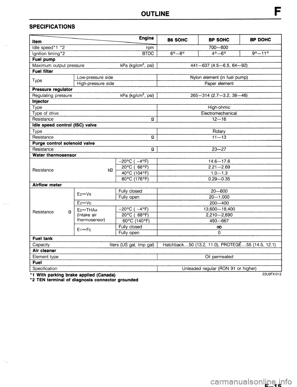
SPECIFICATIONS
Item
Idle speed*1 *2
Ignition timing*2
Fuel pump
Maximum outout Dressure Engine
rpm B6 SOHC
6O--80 BTDC 1
kPa (ka/cm’. osi1 1 BP SOHC
700-800
4O---6O BP DOHC
90-l 1 O
441-637 (4.5-6.5. 64-92) I
I Fuel filter I
Type Low-pressure side Nylon element (in fuel pump)
High-pressure side Paper element
Pressure reaulator
Regulating pressure kPa (kg/cm’, psi) 1 265-314 (2.7-3.2, 38-46)
I lniector I
Type Type of drive
Resistance
Idle speed control (ISC) valve
TvDe , ,
t Resistance
Purge control solenoid valve
Resistance
Water thermosensor n High-ohmic
Electromechanical
12-16
Rotarv
n I II-13 I
n 1 23-27
1 -20% I -4OFj 1 14.6-17.8
Resistance k62 2ooc i 68OF) 2.21-2.69
40°C (104OF) 1.0-l .3
80°C (176OF) 0.29-0.35
Airflow meter
E2++Vs
E2-Vc Fully closed
Fully open 20-600
20-l ,000
200-400
Capacity liters (US gal, Imp gal) 1 Hatchback 50 (13.2, ll.O), PROTEGE ,... 55 (14.5, 12.1)
I Air cleaner I
Element type
Fuel
Specification l
l Wlth parking brake applied (Canada)
‘2 TEN terminal of diagnosis connector grounded Oil permeated
Unleaded regular (RON 91 or higher) 23UOFX-012
F-l 5
Page 308 of 1164
![MAZDA 323 1989 Factory Repair Manual F TROUBLESHOOTING GUIDE
8 ROUGH IDLE/ENGINE STALLS AT IDLE - ALWAYS
bESCRIP- l Engine starts normally but stalls or vibrates excessively at idle in every condition
‘ION TROUBLESHOOTING HINTS]
D MAZDA 323 1989 Factory Repair Manual F TROUBLESHOOTING GUIDE
8 ROUGH IDLE/ENGINE STALLS AT IDLE - ALWAYS
bESCRIP- l Engine starts normally but stalls or vibrates excessively at idle in every condition
‘ION TROUBLESHOOTING HINTS]
D](/manual-img/28/57053/w960_57053-307.png)
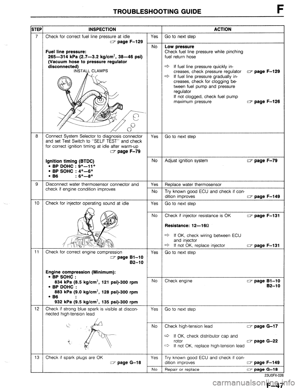
F TROUBLESHOOTING GUIDE
8 ROUGH IDLE/ENGINE STALLS AT IDLE - ALWAYS
bESCRIP- l Engine starts normally but stalls or vibrates excessively at idle in every condition
‘ION TROUBLESHOOTING HINTS]
D Air/Fuel mixture too lean @ Incorrect idle speed
l Air leakage l Idle speed misadjustment l Fuel injection control malfunction l Idle speed control malfunction
*Low fuel line pressure @ One or more spark plugs not firing
3 One or more injectors clogged or not operating @ Low engine compression
3 Low intake air amount @ Airflow meter stuck INSPECTION
1
1
2
3
4
5
6
- Check if “00” is displayed on Self-Diagnosis
Checker with ignition switch ON w page F-82
SYSTEM2ELECT: 1
M v’SELECT SW: A TEST
Check if ECU terminal voltages are OK
MTX...Especially 2D, 20 and 2Q
ATX... Especially 2B, 2E and 3D CT page F-150
Disconnect high-tension lead at idle and check if
engine speed decreases equally at each cylinder
Check for injector operating sound at idle
Check if battery voltage exists at injector connec-
tor (W/R) wire
Check if strong blue spark is visible at discon-
nected high-tension lead
, Yes No Service Code No. displayed
Check for cause (Refer to specified
:heck sequence) “88” flashes
Check ECU terminal IF voltage CT page F-150
Specification: Battery voltage
(Ignition switch ON)
3 If OK, replace ECU w page F-149 3 If not OK, check wiring between
ECU and Self-Diaanosis Checker Yes
Go to next step No
Check for cause Yes
Go to Step 8 No
Go to next step
Go to Step 6
Go to Step 5 Yes
No
Yes
No
Yes
No I-
30 to next step w page F-83
0 page F-151
Check if injector resistance is OK c7 page F-131
Resistance: Approx. 12-l 852
c3 If OK, check wiring between ECU
and injector
c3 If not OK, replace injector w page F-131
Check wiring between ECU and injector
Go to next step
Check high-tension lead w page G-17
Q If OK, check distributor cap and
rotor w page G-22
c3 If not OK, replace high-tension lead
F-42
Page 313 of 1164

TROUBLESHOOTING GUIDE F
Fuel line pressure:
265-314 kPa (2.7-3.2 kg/cm’, 36-46 psi)
(Vacuum hose to pressure regulator Ine pressure while pinching
d If fuel line pressure quickly in-
creases, check pressure regulator w page F-129
* If fuel line pressure gradually in-
If not clogged, check fuel pump
maximum pressure w page F-126
Ignition timing (BTDC)
l BP DOHC : go-1 1 o l BP SOHC : 4”-6O
Resistance: 12-l 60
eck wiring between ECU
Engine compression (Minimum):
l BP SOHC :
634 kPa (6.5 kg/cm2, 121 psi)900 rpm
check distributor cap and
23UOFX-02
F-47
Page 391 of 1164

FUEL SYSTEM F
DIAGNOSI&ONNECTOR
03UOFX-138
I I 23UOFX-110
,
DISCONNECT CONNECTOR
REAR SEAT C
23UOFX-11
03UOFX-11
OBUOFX-11
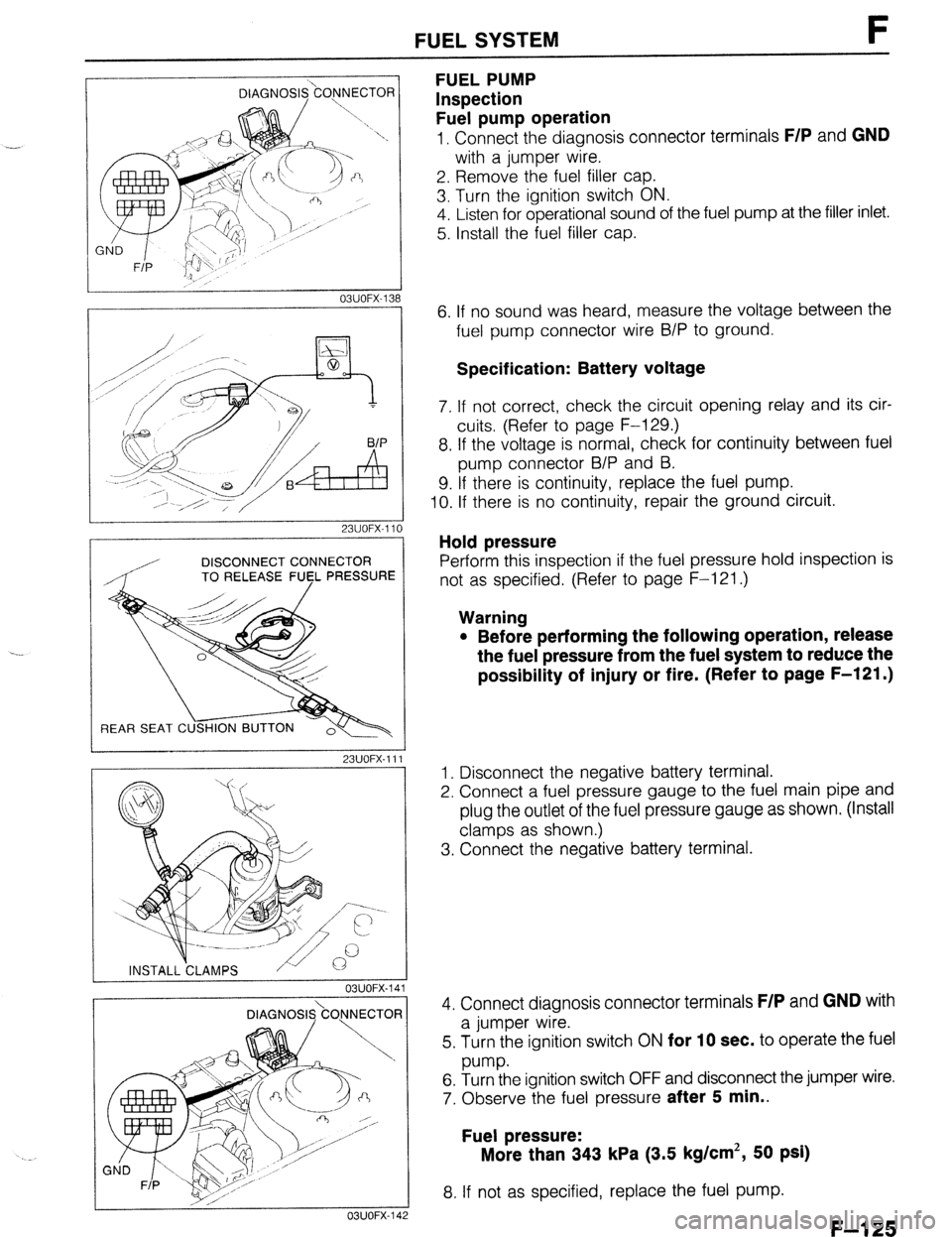
FUEL PUMP
Inspection
Fuel pump operation
1, Connect the diagnosis connector terminals F/P and GND
with a jumper wire.
2. Remove the fuel filler cap.
3. Turn the ignition switch ON.
4. Listen for operational sound of the fuel pump at the filler inlet.
5. Install the fuel filler cap.
6. If no sound was heard, measure the voltage between the
fuel pump connector wire B/P to ground.
Specification: Battery voltage
7. If not correct, check the circuit opening relay and its cir-
cuits (Refer to page F-129.)
8. If the voltage is normal, check for continuity between fuel
pump connector B/P and B.
9. If there is continuity, replace the fuel pump.
IO. If there is no continuity, repair the ground circuit.
Hold pressure
Perform this inspection if the fuel pressure hold inspection is
not as specified. (Refer to page F-121 .)
Warning
l Before performing the following operation, release
the fuel pressure from the fuel system to reduce the
possibility of injury or fire. (Refer to page F-121 .)
1. Disconnect the negative battery terminal.
2. Connect a fuel pressure gauge to the fuel main pipe and
plug the outlet of the fuel pressure gauge as shown. (Install
clamps as shown.)
3. Connect the negative battery terminal.
4. Connect diagnosis connector terminals
F/P and GND with
a jumper wire.
5. Turn the ignition switch ON
for 10 sec. to operate the fuel
w-w.
6. Turn the ignition switch OFF and disconnect the jumper wire.
7. Observe the fuel pressure
after 5 min..
Fuel pressure:
More than 343 kPa (3.5 kg/cm’, 50 psi)
8. If not as specified, replace the fuel pump.
F-l 25