1989 MAZDA 323 air bleeding
[x] Cancel search: air bleedingPage 473 of 1164
H
CLUTCH
INDEX ......................................................
OUTLINE ..................................................
SPECIFICATIONS .................................... H- 3
TROUBLESHOOTING GUIDE.. .................... H- 3
CLUTCH FLUID ......................................... H- 4
PREPARATION ....................................... H- 4
REPLACEMENT ...................................... H- 4
CLUTCH PEDAL ....................................... H- 5
ADJUSTMENT ........................................ H- 5
REMOVAL / INSPECTION / INSTALLATION.. H- 6
CLUTCH MASTER CYLINDER.. ................... H- 7
PREPARATION ....................................... H- 7
REMOVAL / INSPECTION / INSTALLATION.. H- 7
AIR BLEEDING ....................................... H- 6
OVERHAUL ............................................ H-10
CLUTCH RELEASE CYLINDER ................... H-l 2
PREPARATION ....................................... H-12
REMOVAL / INSTALLATION ...................... H-l 2
AIR BLEEDING (REFER TO PAGE H-8)
OVERHAUL ............................................ H-13
CLUTCH UNIT .......................................... H-14
PREPARATION ....................................... H-14
REMOVAL I INSTALLATION.. .................... H-15
RELEASE BEARING .................................. H-17
INSPECTION .......................................... H-17
CLUTCH COVER ....................................... H-17
INSPECTION .......................................... H-17
CLUTCH DISC .......................................... H-17
INSPECTION .......................................... H-17
PILOT BEARING ....................................... H-16
INSPECTION .......................................... H-16
FLYWHEEL ............................................... H-16
INSPECTION .......................................... H-16
23UOHX-001
Page 474 of 1164
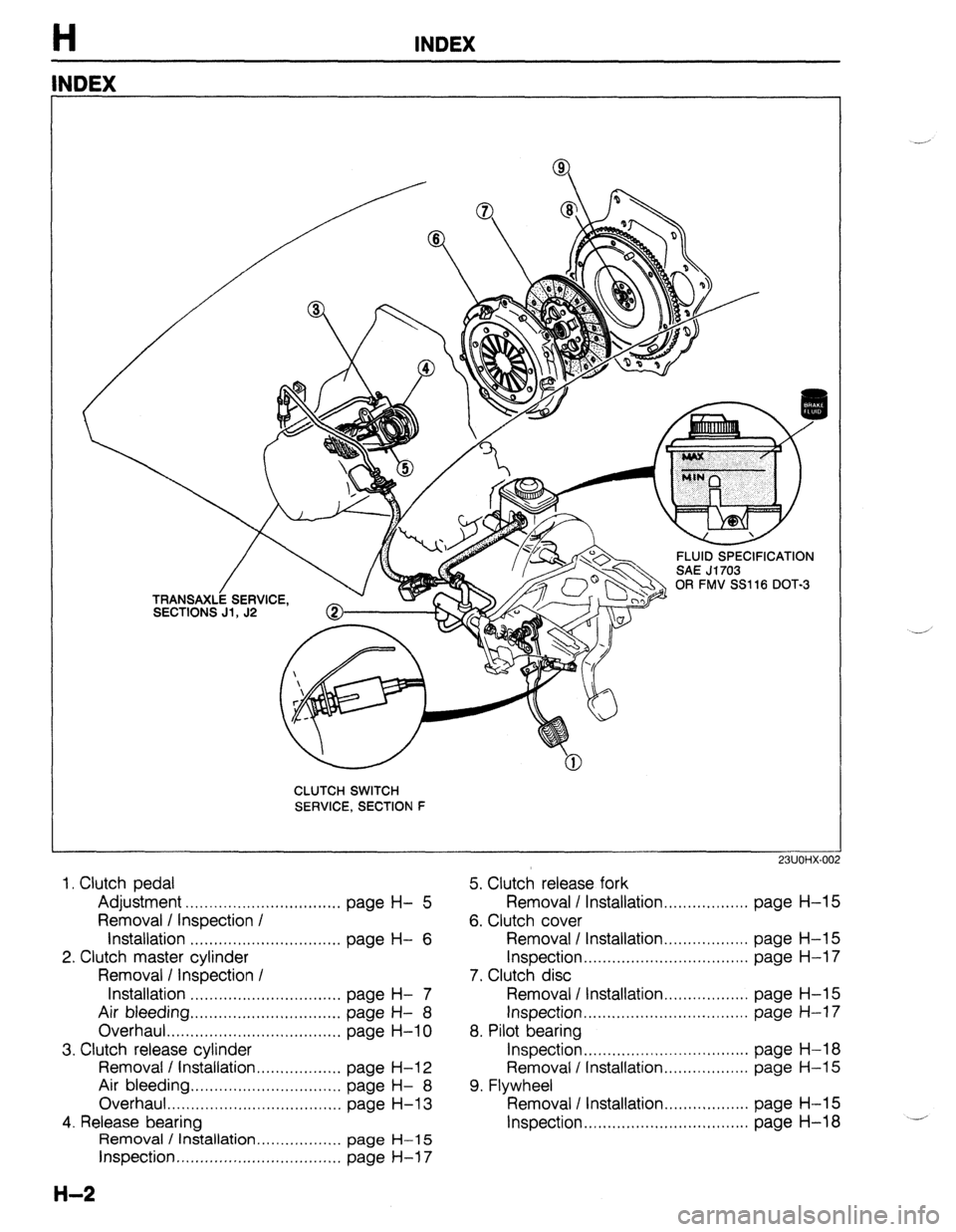
H INDEX
NDEX
CLUTCH SWITCH
SERVICE, SECTION F
23UOHX-00:
2
5. Clutch release fork
Removal / Installation . . . . . . . . . . . . . . . . . . page
H-l 5
6. Clutch cover 1. Clutch pedal
Adjustment . . . . . . . . . . . . . . . . . . . . . . . . . . . . . . . . .
page H- 5
Removal / Inspection /
installation . . . . . . . . . . . . . . . . . . . . . . . . . . . . . . . .
page H- 6
2. Clutch master cylinder
Removal I Inspection I
Installation . . . . . . . . . . . . . . . . . . . . . . . . . . . . . . . .
page H- 7
Air bleeding ,............,..... I ,.,........, page H- 8
Overhaul . . . . . . . . . . . . . . . . . . . . . . . . I ,,.,........
page H-10
3. Clutch release cylinder
Removal / Installation.. . . . . . . . . . . . . . . . . page
H-l 2
Air bleeding . . . . . . . . . . . ..*..................
page H- 8
Overhaul . . . . . . . . . . . . . . . . . . . . . . . . . . . . . . . . . . . . .
page
H-l 3
4. Release bearing
Removal / installation . . . . . . . . . . . . . . . . . . page
H-l 5
Inspection ,.....,..,.,~.,..........,.,,..,,.. page H-l 7
H-2
Removal / Installation .,.......,..,..... page H-l 5
Inspection . . . . . . . . . . . . . . . . . . . . . . . . . . . . . . . . . . .
page H-l 7
7. Clutch disc
Removal I Installation . . . . . . . . . . . . . . . . . . page
H-l 5
Inspection . . . . . . . . . . . . . . . . . . . . . . . . . . . . . . . . . . .
page H-l 7
8. Pilot bearing
Inspection . . . . . . . . . . . . . . . . . . . . . . . . . . . . . . . . . . .
page H-l 8
Removal / Installation.. . . . . . . . . . . . . . . .
page H-l 5
9. Flywheel
Removal I Installation . . . . . . . . . . . . . . . . . . page
H-l 5
Inspection . . . . . . . . . . . . . . . . . . . . . . . . . . . . . . . . . . . page H-18
Page 476 of 1164
H CLUTCH FLUID
CLUTCH FLUID
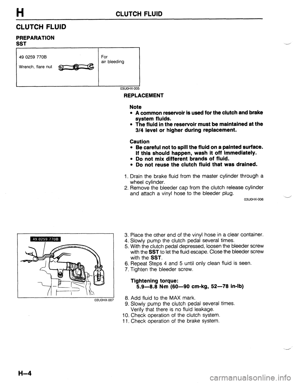
PREPARATION
SST
49 0259 7708 For
Wrench, flare nut ~ air bleeding
03UOHX-007
REPLACEMENT
Note
l A common reservoir is used for the clutch and brake
system fluids.
l The fluid in the reservoir must be maintained at the
3/4 level or higher during replacement.
Caution
l Be careful not to spill the fluid on a painted surface.
If this should happen, wash it off Immediately.
l Do not mix different brands of fluid.
l Do not reuse the clutch fluid that was drained.
1. Drain the brake fluid from the master cylinder through a
wheel cylinder.
2. Remove the bleeder cap from the clutch release cylinder
and attach a vinyl hose to the bleeder plug.
03UOHX-006 -
3. Place the other end of the vinyl hose in a clear container.
4. Slowly pump the clutch pedal several times.
5. With the clutch pedal depressed, loosen the bleeder screw
with the
SST to let the fluid escape. Close the bleeder screw
with the
SST.
6. Repeat Steps 4 and 5 until only clean fluid is seen.
7. Tighten the bleeder screw.
Tightening torque:
5.9-8.8 N.m (80-90 cm-kg, 52-78 in-lb)
8. Add fluid to the MAX mark.
9. Slowly pump the clutch pedal several times.
Verify that there is no fluid leakage.
10. Check operation of the clutch system.
11. Check operation of the brake system.
H-4
Page 479 of 1164
CLUTCH MASTER CYLINDER H
CLUTCH MASTER CYLINDER
PREPARATION
SST
49 0259 770B
Wrench, flare nut For
disconnecting
and connecting
clutch pipe
I I 03UOHX-01
REMOVAL / INSPECTION / INSTALLATION
Caution
l Clutch fluid will damage painted surfaces. Be sure to use a container or rags to collect it. If
fluid gets on a painted surface, wipe it off immediately with a rag.
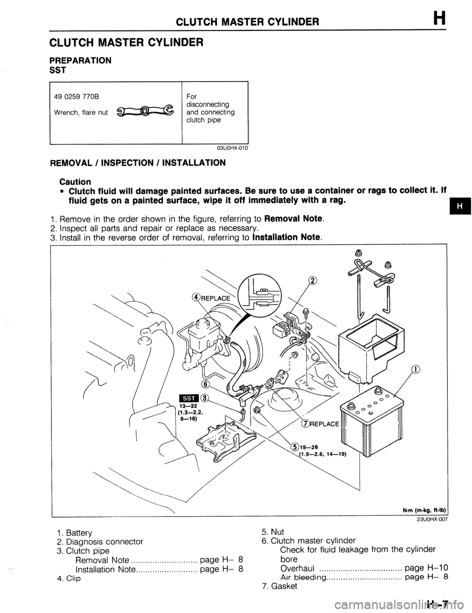
1. Remove in the order shown in the figure, referring to Removal Note.
2. Inspect all parts and repair or replace as necessary.
3. Install in the reverse order of removal, referring to
Installation Note.
N.m (m-kg, R-lb
23UOHX-007
1. Battery
2. Diagnosis connector
3. Clutch pipe
Removal Note . . . . . . . . . . . . . . . . . . . . . . . . . . . page H- 8
Installation Note . . . . . . . . . . . . . . . . . . . . . . . . . . page H-
8
4. Clip
5. Nut
6. Clutch master cylinder
Check for fluid leakage from the cylinder
bore
Overhaul . . . . . . . ..*........*................ page H-10
Air bleeding . . . . . . . . . . . . . . . . . . . . . . . . . . . . . . . . page H- 8
7. Gasket
H-7
Page 480 of 1164
H CLUTCH MASTER CYLINDER
23UOHX-Ot ,a
\ I 03UOHX-016
7
I
03UOHX-014
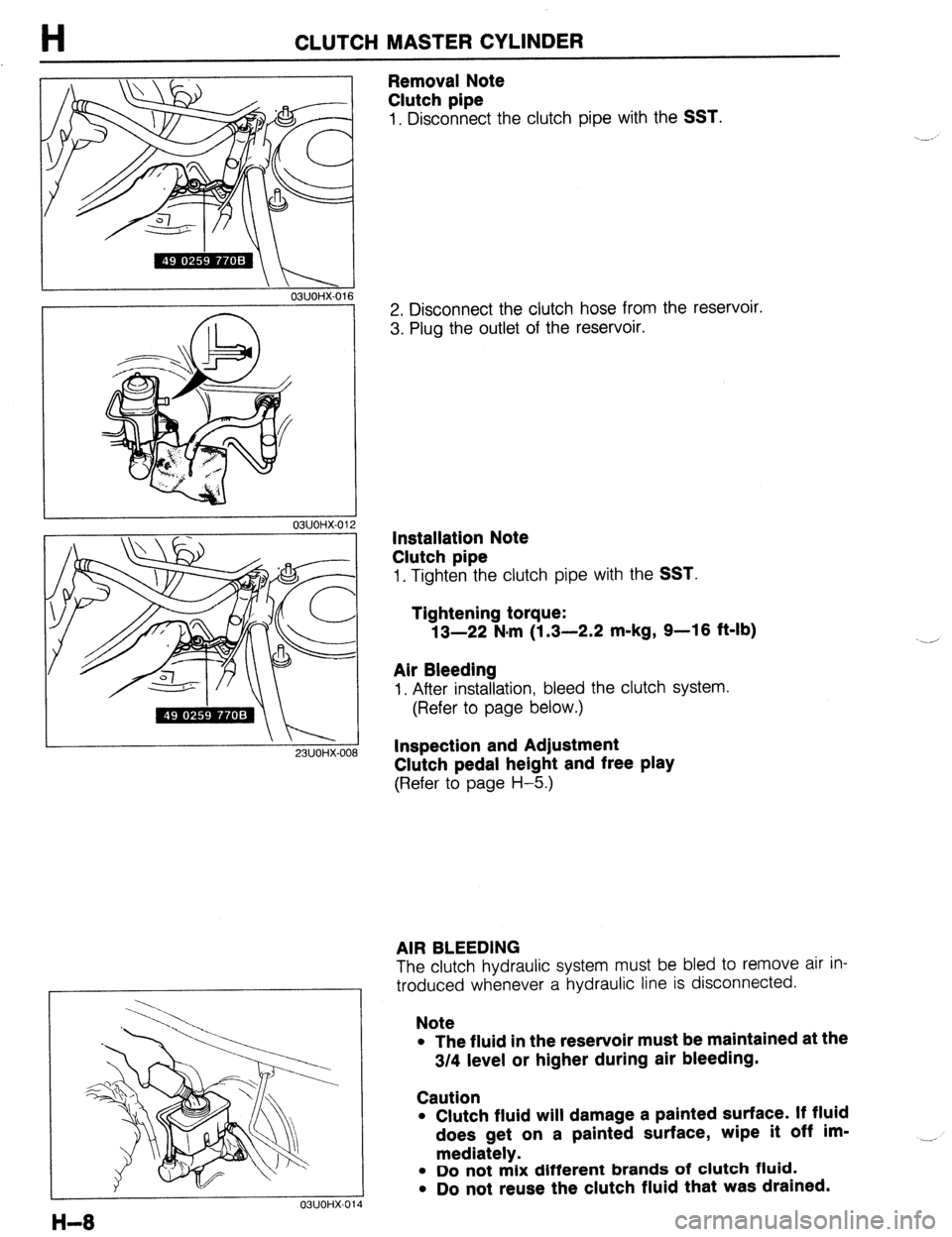
Removal Note
Clutch pipe
1, Disconnect the clutch pipe with the SST.
2. Disconnect the clutch hose from the reservoir.
3. Plug the outlet of the reservoir.
Installation Note
Clutch pipe
1. Tighten the clutch pipe with the SST.
Tightening torque:
13-22 N.m (1.3-2.2 m-kg, 9-16 ft-lb)
Air Bleeding
I. After installation, bleed the clutch system.
(Refer to page below.)
Inspection and Adjustment
Clutch pedal height and free play
(Refer to page H-5.)
AIR BLEEDING
The clutch hydraulic system must be bled to remove air in-
troduced whenever a hydraulic line is disconnected.
Note
l The fluid in the reservoir must be maintained at the
3/4 level or higher during air bleeding.
Caution
l Clutch fluid will damage a painted surface. If fluid
does get on a painted surface, wipe it off im-
mediately.
l Do not mix different brands of clutch fluid.
l Do not reuse the clutch fluid that was drained. __,
Page 485 of 1164
CLUTCH RELEASE CYLINDER
Installation Note
Clutch pipe
H
1. Tighten the clutch pipe with the SST.
Tightening torque:
13-22 N-m (1.3-2.2 m-kg, 9-16 ft-lb)
Air Bleeding
1. After installation, bleed the clutch system.
(Refer to page below.)
23UOHX-011
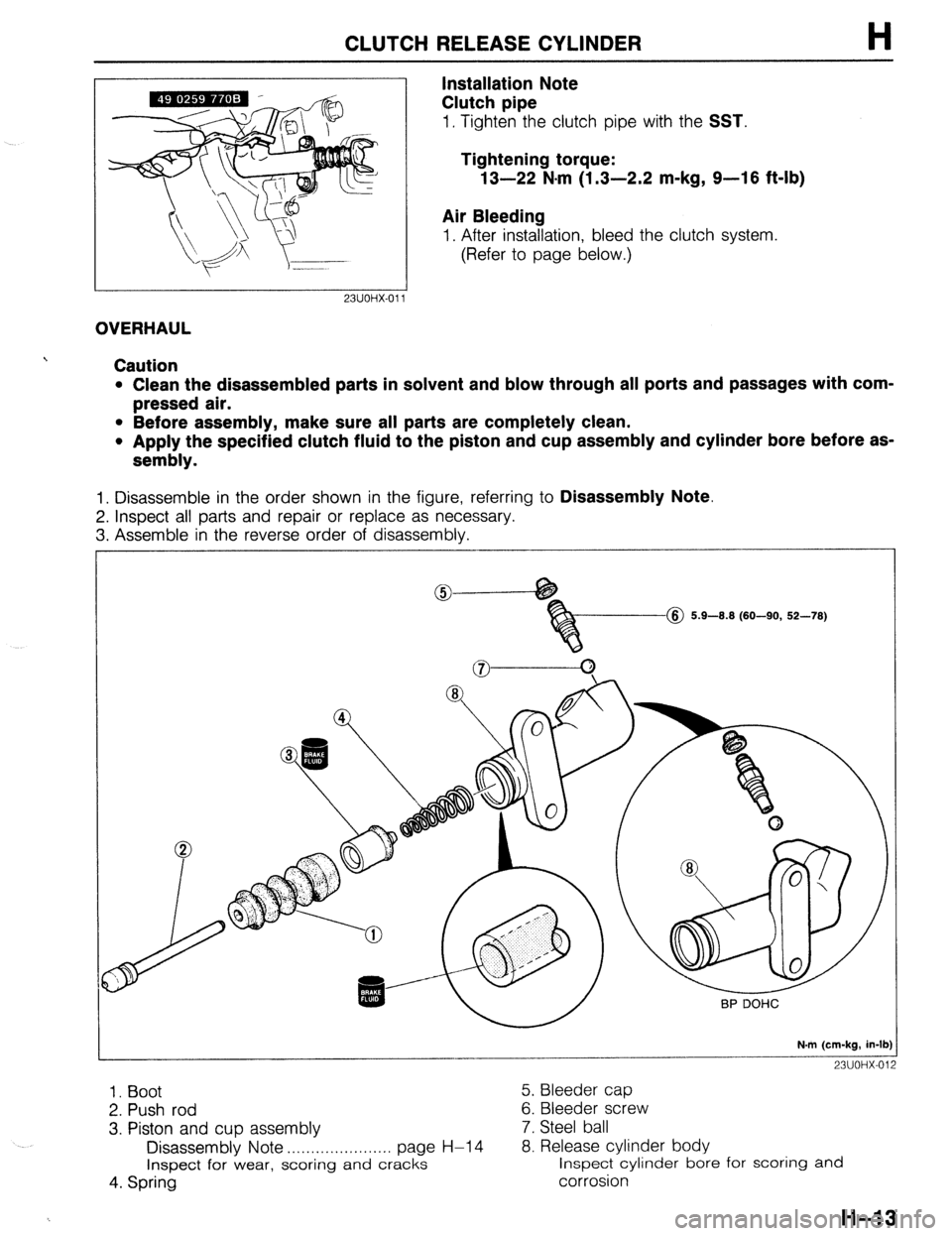
OVERHAUL
Caution
l Clean the disassembled parts in solvent and blow through all ports and passages with com-
pressed air.
l Before assembly, make sure all parts are completely clean.
l Apply the specified clutch fluid to the piston and cup assembly and cylinder bore before as-
sembly.
1. Disassemble in the order shown in the figure, referring to Disassembly Note.
2. Inspect all parts and repair or replace as necessary.
3. Assemble in the reverse order of disassembly.
@ 5.9-8.8 (60-90, 52-78)
N.m (cm-kg, in-lb)
23UOHX-012
1. Boot 5. Bleeder cap
2. Push rod 6. Bleeder screw
3. Piston and cup assembly 7. Steel ball
Disassembly Note . . . . . . . . . . . . . . . . . . . . . . page H-l 4 8. Release cylinder body
Inspect for wear, scoring
and cracks inspect cylinder bore for scoring and
4. Spring corrosion
H-13
Page 625 of 1164
N
STEERING SYSTEM
INDEX ......................................................
MANUAL STEERING ............................... ;I g
ENGINE SPEED SENSING POWER
STEERING (ESPS) ................................. N- 3
OUTLINE ..................................................
SPECIFICATIONS .................................... ;I ::
MANUAL STEERING ..................................
PREPARATION ....................................... ;I ;
TROUBLESHOOTING GUIDE.. .................. N- 5
BOOT ................................................... N- 6
STEERING WHEEL AND COLUMN.. .......... N- 6
STEERING GEAR AND LINKAGE .............. N-13
ENGINE SPEED SENSING POWER
STEERING .............................................. N-23
PREPARATION ....................................... N-23
TROUBLESHOOTING GUIDE.. .................. N-25
AIR BLEEDING ....................................... N-26
STEERING WHEEL AND COLUMN.. .......... N-26
POWER STEERING FLUID.. ...................... N-27
STEERING GEAR AND LINKAGE .............. N-30
POWER STEERING OIL PUMP.. ................ N-37
DRIVE BELT ........................................... N-41
23UONX-001
Page 627 of 1164
INDEX
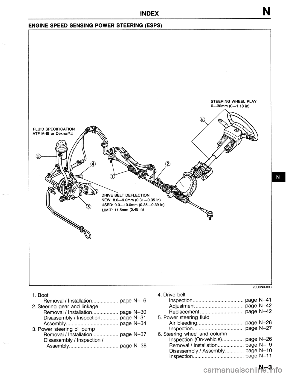
ENGINE SPEED SENSING POWER STEERING (ESPS)
FLUID
ATF M STEERING WHEEL PLAY
O-30mm (O-l .18 in)
SPECIFICATION
-IIt or Dexron@lI
I T nFFl FCTIC-IN
--. --w. .-.. NEW: 8.0-9.0mm (0.31-0.35 in)
USED: 9.0-lO.Omm (0.35-0.39 in)
LIMIT: 11.5mm (0.45 in)
23UONX-00
1. Boot
4. Drive belt
Removal / installation
.................. page N- 6 Inspection ................................... page N-41
2. Steering gear and linkage Adjustment .................................
page N-42
Removal / Installation.. ................ page N-30 Replacement .............................. page N-42
Disassembly / Inspection.. ..........
page N-31 5. Power steering fluid
Assembly..
.................................. page N-34 Air bleeding ................................ page N-26
3. Power steering oil pump Inspection.. .................................
page N-27
Removal I Installation
.................. page N-37 6. Steering wheel and column
Disassembly / Inspection I Inspection (On-vehicle).
.............. page N-26
Assembly ..................................
page N-38 Removal / Installation..
................ page N- 9
Disassembly / Assembly ............. page
N-l 0
Inspection ................................... page N-l 1
N-3