1989 MAZDA 323 Absorber
[x] Cancel search: AbsorberPage 707 of 1164

R
SUSPENSION
INDEX ...................................................... R- 2
FRONT SUSPENSION ..............................
R- 2
REAR SUSPENSION ................................ R- 3
OUTLINE .................................................. R- 4
SPECIFICATIONS ....................................
TROUBLESHOOTING GUIDE.. .................... ;I ;
WHEEL ALIGNMENT ................................. R- 7
PRE-INSPECTION ....................................
FRONT WHEEL ALIGNMENT.. .................. ;I ;
REAR WHEEL ALIGNMENT.. .................... R- 9
FRONT SUSPENSION (STRUT). .................. R-l 0
PREPARATION ....................................... R-l 0
FRONT SHOCK ABSORBER AND SPRING . . R-11
FRONT LOWER ARM
............................... R-l 6
FRONT STABILIZER ................................
R-l 6
REAR SUSPENSION (STRUT). .................... R-20
PREPARATION ....................................... R-20
REAR SHOCK ABSORBER AND SPRING .... R-21
LATERAL LINK AND TRAILING LINK.. ....... R-26
REAR STABILIZER .................................. R-27
REAR CROSSMEMBER ............................ R-29
23UORX-001
Page 708 of 1164

R INDEX
INDEX
FRONT WHEEL ALIGNMENT
TOTAL TOE-IN: 2 -1: 3mm (0.08 f 0.12 in, 0.2’ * 0.3’)
MAXIMUM STEERING ANGLE: 40=’ * 2’ (INNER)
33“ f 2O (OUTER)
CAMBER ANGLE: -O”05’ * 45’
CASTER ANGLE: lo55 f 55
KINGPIN ANGLE: 12“25 FRONT
irr
FRONT SUSPENSION
1. Front shock absorber and spring
Removal I Installation . . . . . . . . . . . . . . . . . . page R-l 1
Disassembly / Inspection . . . . . . . . . . . . page R-l 2
Inspection . . . . . . . . . . . . . . . . . . . . . . . . . . . . . . . . page R-l 3
Assembly . . . . . . 1 . . . . . . . . . . . . . . . . . . . . . . . . . . . . . page R-l 4
2. Front lower arm
Removal / Inspection I
Installation ,,...,.......,...........,.._..,. page R-l 6
Inspection . . . . . . . . . . . . . . . . . . . . . . . . . . . . . . . . . . . page R-l 7
R-2
3. Front stabilizer
Removal / Inspection /
Installation, . . . . . . ,. . . . . . . . . . . . . . . . . . . . . . . . . page R-l 8
Page 709 of 1164

INDEX
REAR WHEEL ALIGNMENT
TOTAL TOE-IN: 2 f 3mm (0.08 f 0.12 in, 0.2O * 0.39
CAMBER ANGLE: -O”20’ * 45’
m
1. Rear shock absorber and spring 3. Rear stabilizer
Removal / Installation . . . . . . . . . . . . . . . . . . page R-21 Removal / Inspection /
Disassembly / Inspection . . . . . . . . . . . . page
R-22 Installation . . . . . . . . . . . . . . . . . . . . . . . . . . ...*... page R-27
Inspection . . . . . . . . . . . . . . . . . . . . . . . . . . . . . . . . . . . page R-23 4. Rear crossmember
Assembly.. . . . . . . . . . . . . . . . . . . . . . . . . . . . . . . . . . .
page R-24 Removal I Installation. . . . . . . . . . . . . . . . . . page R-29
2. Lateral link and trailing link
Removal / Inspection /
Installation . . . . . . . . . . . . . . . . . . . . . . . . . . . . . . . . . page R-26
Page 710 of 1164
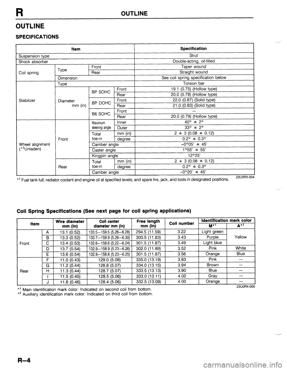
R OUTLINE
OUTLINE
SPECIFICATIONS
Suspension type Item Specification Strut
Shock absorber Double-acting, oil-filled
Coil spring
Stabilizer Type Front Taper wound
Rear Straight wound
Dimension See coil spring specification below
Type Torsion bar
BP SOHC Front 19.1 (0.75) (Hollow type)
Rear 20.0 (0.79) (Hollow type)
Diameter 22.0 (0.87) (Solid type)
mm (in) BP DOHC ;eTrt
21 .O (0.83) (Solid type)
P ,
-
66 SOHC rronr
Rear 20.0 (0.79) (Hollow type)
Maximum Inner 400 f 20
steering angle
Outer 330 f 20
Total mm (in) 2 f 3 (0.08 f 0.12)
Front toe-in
degree 0.2O f 0.3O
Wheel alignment
(*‘Unladen) Camber angle -0005’ f 45’
Caster angle 1055 * 55’
Kingpin angle 12O25’
Total mm (in) 2 f 3 (0.08 * 0.12)
Rear toe-in
degree 0.2O f 0.3O
Camber angle -0°20’ f 45’
*’ Fuel tank full; radiator coolant and engine oil at specified levels; and spare tire, jack, and tools in designated positions.
23UORX.004
Coil Spring Specifications (See next page for coil spring applications)
I Item Wire diameter Coil center Free lel.=-. .
mm iin1 rliamotor mm [in mm (in 1 coil numbs
Front
nath
1 _ . . *St Identification mark color +l
., . . . . I...,
-*.....-.“, * . . . . . ,..-, -....- I--‘, M iA*=
A 13.1 (0.52) 133.5-159.5 (5.26-6.28)
294.5 (11.59) 3.22 Light green
B 13.3 (0.52) 133.7-159.9 (5.26-6.30) 300.5 (11.83)
3.43 Purple Yellow
C 13.4 (0.53)
132.6-158.6 (5.22-6.24) 301.5 (11.87) 3.49
Light blue
D 13.7 (0.54)
132.9-158.9 (5.23-6.26) 302.0 (11.89) 3.52
Pink White
I F I 12f3 Kl5Al I 1.17 A-l!% 8 f!i PR-Fi 751
I RrIl .5 II 1 6x71 I 3.56 Orange
Blue
3 83 Pink -
Brown - .“._ \“.- .,
. “W.., ~ - -. - \-. -- -. - -, -- .-
\’ .‘-‘I t
F 11 .o (0.43) 129.0 (5.08)
335.0 (13.19) -.--
G 11.2 (0.44) 128.8 (5.07)
334.0 (13.15) 3.94
Rnnr l-4
1 I ? 07 AA 1387 /5n7
.?m !i 113 1% 3 an Blue - I I I I .” \v.-7, I&V., \V.“., ---.., \.-. .-, I 11.5 (0.45) 128.5 (5.06)
333.0 (13.11) i:oi Gray
-
J 11.6 (0.46) 128.4 (5.06)
332.5 (13.09) 4.00 Orange
-
l ’ Main identification mark color: Indicated on second coil from bottom.
*’ Auxiliary identification mark color: Indicated on third coil from bottom. 23UORX-005
R-4
Page 712 of 1164

TROUBLESHOOTING GUIDE
TROUBLESHOOTING GUIDE
Problem Possible Cause Action Page
Body “rolls” Weak stabilizer Replace R-18, 27
Worn or deteriorated stabilizer bushing Replace R-18, 27
Worn or deteriorated lower arm bushing
Replace R-16
Malfunction of shock absorber
Replace R-11,21
Poor riding comfort Weak coil spring Replace R-12, 22
Malfunction of shock absorber Replace R-11,21
Body leans Weak coil spring Replace R-12, 22
Worn or deteriorated stabilizer bushing
Replace R-18, 27
Worn or deteriorated lower arm bushing Replace R-16
Abnormal noise from Poor lubrication or wear of lower arm ball joint Lubricate or replace R-16
suspension system Looseness of peripheral connections Tighten -
Malfunction of shock absorber Replace R-11, 21
Worn or deteriorated stabilizer bushing Replace R-18, 27
Worn or deteriorated lower arm bushing
Replace R-16
General driving Weak coil spring Replace R-12, 22
Instability Malfunction of shock absorber Replace R-11, 21
Worn or deteriorated lower arm bushing Replace R-16
Worn or deteriorated stabilizer bushing Replace R-18, 27
Improperly adjusted wheel alignment Adjust R- 7
Damaged lower arm ball joint
Replace R-l 6
Malfunction of steering system -
Section N
Damaged or unbalanced wheel(s) -
Section Q
Heavy steering
Poor lubrication or wear of lower arm ball joint Lubricate or replace R-16
Improperly adjusted wheel alignment
Adjust R- 7
Malfunction of steering system -
Section N
Damaged or unbalanced wheel(s) -
Section Q
Steerlng wheel pulls to Weak coil spring
Replace R-12, 22
one side
Worn or deteriorated stabilizer bushing Replace R-18, 27
Worn or deteriorated lower arm bushing Replace R-16
Damaged lower arm ball joint Replace R-16
Improperly adjusted wheel alignment Adjust R- 7
Malfunction of steering system -
Section N
Malfunction of braking system -
Section P
Damaged or unbalanced wheel(s) -
Section Q
“Shimmy” occurs Damaged lower arm ball joint Replace R-16
(Steering wheel vibrates Malfunction of shock absorber
Replace R-11, 21
left/right) Loose shock absorber mounting
Tighten R-11, 21
Worn or deteriorated lower arm bushing
Replace R-16
Worn or deteriorated stabilizer bushing Replace R-18, 27
Improperly adjusted wheel alignment
Adjust R- 7
Damaged or worn wheel bearing Replace Section M
Malfunction of steering system -
Section N
Damaged or unbalanced wheel(s) -
Section Q
Steering wheel doesn’t Stuck or damaged lower arm ball joint
Replace R-16
return properly Improperly adjusted wheel alignment Adjust R- 7
Malfunction of steering system -
Section N
Damaged or unbalanced wheel(s) -
Section Q
_-..--..__
23UUHXJJC
.-_,
.-
R-6
Page 713 of 1164

WHEEL ALIGNMENT
WHEEL ALIGNMENT
PRE-INSPECTION
1. Check the tire inflations and set to the recommended pressure, if necessary.
2. Inspect the front wheel bearing play; replace the bearing if necessary.
3. inspect the wheel and tire runout.
4. Inspect the ball joints and steering linkage for any excessive looseness.
5. The vehicle must be on level ground and have no luggage or passenger load.
6. The difference in height between the left and right sides from the center of the wheel to the fender brim
must not exceed
10mm (0.39 in).
7. Shake the vehicle to check operation of the shock absorbers.
03UORX.007
FRONT WHEEL ALIGNMENT
Specifications
item
Specifications
Maximum Inner 4o” f: 2O
steering angle Outer
33O f 2O
Total mm (in) 2 f 3 (0.08 f 0.12)
toe-in dearee 0.20 f 0.30 Wheel alignment
(*‘Unladen) Front
*I Fuel tank full; radiator coolant and Camber angle -0005 * 45’
Caster angle 1°55’ f 55’
Kingpin angle 12O25’
engine oil at specified level; and spare tire, jack, and tools in designated positions.
23UORX-008
I
I 23UORX-023
Adjustments
Maximum steering angle
1. Loosen the left and right tie rod locknuts, then turn the tie
rods equally.
Maximum left/right difference: 3mm (0.12 in)
2. Tighten the tie rod locknuts.
Tightening torque:
34-50 N-m (3.5-5.1 m-kg, 25-37 ft-lb)
3. Adjust the toe-in after adjusting the steering angle.
4. Inspect and adjust the toe-in after adjusting the turning angle.
I 23UORX-024
R-7
Page 717 of 1164

R
FRONTSHOCKABSORBERANDSPRING
Removal / Installation
1. Jack up the front of the vehicle and support it with safety stands.
2. Remove the wheels.
3. Remove in the order shown in the figure.
4. Install in the reverse order of removal, referring to Installation Note.
5. After installation, measure the front wheel alignment, and adjust it if necessary.
Caution
l Retighten the shock absorber lower bolts to the specified torque after lowering the vehicle
(unladen condition).
1. Clip
2. Nut
3. Bolt
4. Nut 5. Shock absorber and spring
N.m (m-kg, R-lb
23UORX-0‘
- .^
Disassembly ............................... page H-l Z
Inspection ................................... page R-l 3
Assembly.. .................................. page R-14
Installation Note.. ........................ page R-12
R-l 1
Page 718 of 1164

FRONT SUSPENSION (STRUT)
Installation note
Shock absorber and spring
1. Face the direction indicator of the mounting block inboard,
and install the shock absorber and spring.
Note
l When facing the indicator to other position, the cam-
ber and caster are changed as shown in the page
R-8. -’
23UORX-017
Disassembly / Inspection
1. Disassemble in the order shown in the figure, referring to Disassembly Note.
2. Visuallv inspect each part and replace as necessary.
1. Cap
2. Piston rod nut
Disassembly Note ,..........,.....,.... page R-13
3. Mounting block
4. Thrust bearing 5. Upper spring seat
6. Rubber spring seat
7. Bound stopper
8. Coil spring
9. Shock absorber
Inspection . . . . . . . . . , . . . . , . . . . . . . . . . . . . . . . . . . . page R-l 3
R-l 2