Page 248 of 1164
OIL PUMP
OWODX-032
r----‘---I ----
L-
---- 05UODX-033
r- __I_.__^--
_- .-.. --.-.__-----^---
---7--l
L-.-.LlLd-..- ..-.---A OWODX-034
___ll_--_l___-----------
___I- 1
.i
5
INSPECTION
Pressure Spring
1 Inspect the spring for weakness or breakage.
2. Measure the free length. Replace the spring if necessary.
Free length: 45.5mm (1.791 in) -
Rotor Clearance
1. Measure the following clearances. Replace the rotor if
necessary.
Tooth tip clearance: 0.20mm (0.0079 in) max.
Outer rotor to pump body clearance:
0.22mm (0.0087 in) max.
Side clearance: 0.14mm (0.0055 in) max.
Assembly Note
Oil seal
1, Apply a small amount of clean engine oil to the lip of a new
oil seal.
2. Push the oil seal slightly in by hand,
Caution
l The oil seal must be pressed in until it is flush with
the edge of the oil pump body.
-’
3. Press the oil seal in evenly with a suitable pipe.
Oil seal outer diameter: 44mm (1.73 in)
Page 383 of 1164
VARIABLE INERTIA CHARGING SYSTEM (VI-)
VARIABLE INERTIA
CHARGING SYSTEM (VICS) [DOHC]
DESCRIPTION
VACUUM CHAMBER
SHUTTER VALVE ACTUATOR
F
THREE-WAY VALVE CLOSED
5,000 rpm
SHUTTER VALVE
BELOW 5,000 rpm ABOVE 5,000 rpm
SHUTTER VALVE CLOSED SHUTTER VALVE OPEN
By varying the length of the intake air path in the intake manifold and dynamic chamber, the resonance
induced inertia charging effect is improved, yielding higher torque and a wider torque band.
The length of the intake track is controlled within the intake manifold and dynamic chamber by opening and
closing the shutter valve at 5,000 rpm.
l-R; FCZz consists of the shutter valves, shutter valve actuator, three-way solenoid valve, vacuum chamber,
F-117
Page 443 of 1164
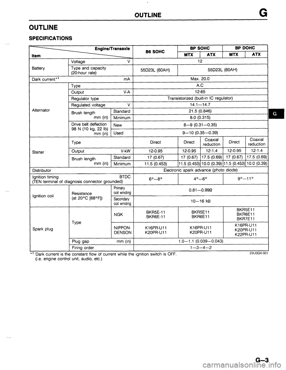
OUTLINE G
OUTLINE
SPECIFICATIONS
Item EnginelTransaxle
‘-2, B6 SOHC BP SOHC BP DOHC
MTX 1 ATX MTX ( ATX
Voltage v 1 12
I
3attery
Dark current*’ Type and capacity
(20-hour rate)
mA 55D23L (60AH) 55D23L (60AH)
Max. 20.0
L\lternator
Starter
Type AC
output V-A 12-65
Regulator type Transistorized (built-in IC regulator)
Regulated voltage V 14.1-14.7
Brush length Standard 21.5 (0.846)
mm (in) Minimum 8.0 (0.315)
Drive belt deflection
New
98 N (10 kg, 22 lb)
mm (in) Used 8-Q (0.31-0.35)
Q-10 (0.35-0.39)
Type
I Direct Direct
I Coaxial
Direct Coaxial
reduction reduction I
output V-kW 12-0.95 12-0.95 12-1.4
12-0.95 12-1.4
Brush length Standard 17 (0.67) 17 (0.67) 17.5 (0.69) 17 (0.67)
17.5 (0.69)
mm (in) Minimum 11.5 (0.453) 11.5 (0.453) 10.0 (0.39) 11.5 (0.453) 10.0 (0.39)
Distributor
Ignition timing BTDC
(TEN terminal of diagnosis connector grounded) Electronic spark advance (photo diode)
6O--8O 4O-6O Q”-1 1 o
Ignition coil
Spark plug Resistance
(at 20% [68OF]) Primary
coil winding 0.81-O.QQg
Secondary
coil winding IO-16 kg
BKR5E-11 BKR5Ell BKR5Ell
NGK
BKR6E-11 BKRGEl 1 BKRGEli
BKR7Ell
Type NIPPON-
DENSON Kl GPR-Ul l
K20PRU 11 KIGPR-Ull
K20PR-Ul l KIGPR-Ull
K20PRUll
K22PR-Ul l
I Plua aao mm (in) I 1.0-l .l (0.039-0.043)
Firing order
’ Dark current is the constant flow of current while the ignition switch is OFF.
(i.e. engine control unit, audio, etc.) l-3-4-2
23lJOGX-00
G-3
Page 599 of 1164
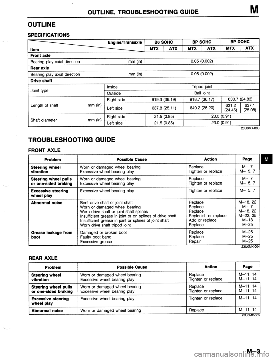
OUTLINE, TROUBLESHOOTING GUIDE M
OUTLINE
SPECIFICATIONS
Engine/Transaxle
86 SOHC
I BP SOHC BP DOHC
MTX 1 ATX 1 MTX 1 ATX
Front axle
Bearing play axial direction Rear axle
Bearina olav axial direction I
mm (in) 0.05 (0.002)
mm (in) I 0.05 (0.002) Drive shaft
j Inside Tripod ioint
I Joint type I -
Outside I Ball ioint 1
Right side 919.3 (36.19)
918.7 (36.17) 630.7 (24.83)
Length of shaft
mm (in)
Left side 637.8 (25.11)
640.2 (25.20) 621.2 637.1
(24.46) (25.08)
Shaft diameter mm (in) Right side 21.5 (0.85) 23.0 (0.91)
Left side
21.5 (0.85)
23.0 (0.91)
23UOMX-003
TROUBLESHOOTING GUIDE
FRONT AXLE Problem
Steering wheel
vibration
Steering wheel pulls
or one-sided braking
Excessive steering
wheel play
Abnormal noise
Grease leakage from
boot Possible Cause Action
Worn or damaged wheel bearing
Excessive wheel bearing play
Worn or damaged wheel bearing
Excessive wheel bearing play
Excessive wheel bearing play Replace
Tighten or replace
Replace
Tighten or replace
Tighten or replace
Bent drive shaft or joint shaft
Worn or damaged wheel bearing
Worn drive shaft or joint shaft splines
Insufficient grease in joint or on splines of drive shaft
insufficient grease in joint or splines of joint shaft
Nom drive shaft tripod joint Replace
Replace
Replace
Replenish or replace
Add or replace
Replace
Damaged or broken boot
Faulty boot band
Excessive grease Replace
Replace
Reoair Page M- 7
M- 5,7
M- 7
M- 5,7
M- 57
M-18, 22
M- 7
M-18, 22
M-22, 25
M-18
M-25
M-25
M-25
M-25
23UOMX-004
REAR AXLE Problem Possible Cause Action Page
Steering wheel
Worn or damaged wheel bearing
Replace M-11, 14 vibration
Excessive wheel bearing play Tighten or replace M-11, 14 Steering wheel pulls
Worn or damaged wheel bearing Replace M-11, 14 or one-sided braking Excessive wheel bearing play Tighten or replace M-11, 14 Excessive steering
Excessive wheel bearing play Tighten or replace M-11, 14 wheel olav
Abnormal noise
Worn or damaged wheel bearing Replace M-11, 14
23UOMX-005
M-3
Page 624 of 1164
DRIVE SHAFT
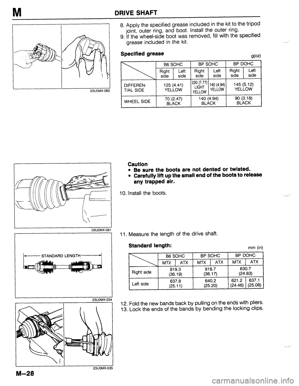
8. Apply the specified grease included in the kit to the tripod
joint, outer ring, and boot. Install the outer ring.
9. If the wheel-side boot was removed, fill with the specified
grease included in the kit.
Specified grease
!J@z)
B6 SOHC BP SOHC BP DOHC
Right Left Right
Left Right Left
side side side side side side
DIFFEREN- 2;&y’ 140 (4.94) 145 (5.12)
TIAL SIDE y;L44;)
YELLOW YELLOW YELLOW
WHEEL SIDE 70 (2.47) 140 (4.94) 90 (3.18)
BLACK BLACK BLACK
23UOMX-03
I I
I
23UOMX-0:
M-28
Caution
l Be sure the boots are not dented or twisted.
. Carefully lift up the small end of the boots to release
any trapped air.
10. Install the boots.
11. Measure the length of the drive shaft.
Standard length: mm (in)
B6 SOHC BP SOHC BP DOHC
MTX 1 ATX MTX 1 ATX MTX 1 ATX
light side 919.3 918.7
630.7
(36.19) (36.17) (24.83)
640.2 621.2 637.1
(25.20) (24.46) (25.08)
I Left side
I 637.8
(25.11)
12. Fold the new bands back by pulling on the ends with pliers.
13. Lock the ends of the bands by bending the locking clips.
Page 635 of 1164
MANUAL STEERING N
13UONX-01
23UONX-05
POSITION
1 SGONX-Oi
23UONX.01 I1
Disassembly note
Steering lock assembly
Use a chisel to make a groove in the head of the steering lock
mounting bolts. Remove the bolts with a screwdriver; then re-
move the steering lock assembly.
Caution
l Secure the shaft in a vise protected with brass pads
or cloth.
Inspection
Check for the following and replace the assembly if necessary.
Steering shaft assembly
1. Column bushing wear.
2. Steering shaft length.
Specified length: 558.3~560.3mm (21.98-22.06 in)
3. Tilt operation.
(1) Verify that the adjusting lever moves smoothly from un-
lock position to lock position.
(2) Verify that the steering shaft is fixed firmly when the ad-
justing lever is locked.
Intermediate shaft, Universal joint
Universal joint looseness, abnormal noise, or sticking.
N-l 1
Page 669 of 1164
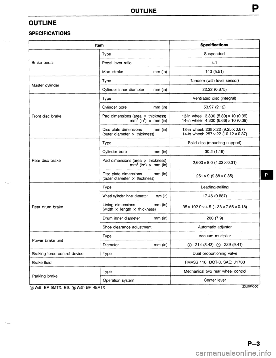
OUTLINE
OUTLINE
SPECIFICATIONS
item Specifications
Brake pedal
Master cylinder
Front disc brake
Rear disc brake
Rear drum brake
Power brake unit
Braking force control device
Brake fluid Type Suspended
Pedal lever ratio
I 4.1
I
Max. stroke mm (in) 140 (5.51)
I
Type
Cylinder inner diameter mm (in)
Type
Cylinder bore mm (in)
Pad dimensions (area x thickness)
mm’ (in2) x mm (in)
Disc plate dimensions mm (in)
(outer diameter x thickness) Tandem (with level sensor)
22.22 (0.875)
Ventilated disc (integral)
53.97 (2.12)
13-in wheel: 3,800 (5.89)x 10 (0.39)
14-in wheel: 4,300 (6.66) x 10 (0.39)
13-in wheel: 235 x 22 (9.25 x 0.87)
14-in wheel: 257 x 22 (10.12 x 0.87)
We
I Solid disc (mounting support)
I
Cylinder bore mm (in)
I 30.2 (1.19)
I
Pad dimensions (area x thickness)
mm2 (in’) x mm (in)
Disc plate dimensions mm (in)
(outer diameter x thickness)
Type 2,600 x 8.0 (4.03 x 0.31)
251 x 9 (9.88 x 0.35)
Leading-trailing
Wheel cylinder inner diameter mm (in) 17.46 (0.687)
I
Lining dimensions mm (in)
(width x length x thickness) 35x192.0x4.5 (1.38x7.56x0.18)
I
Drum inner diameter mm (in) 200 (7.9)
I
Shoe clearance adjustment Automatic adjuster
Vacuum multiplier
@ : 214 (8.43) @ : 239 (9.41)
Dual proportioning valve
FMVSS 116: DOT-3, SAE: J1703
Type
Diameter
Type mm (in)
Parking brake
Type
Operation system Mechanical two rear wheel control
Center lever I
3 With BP SMTX, B6, @With BP 4EATX
I I
23UOPX-001
P-3
Page 795 of 1164
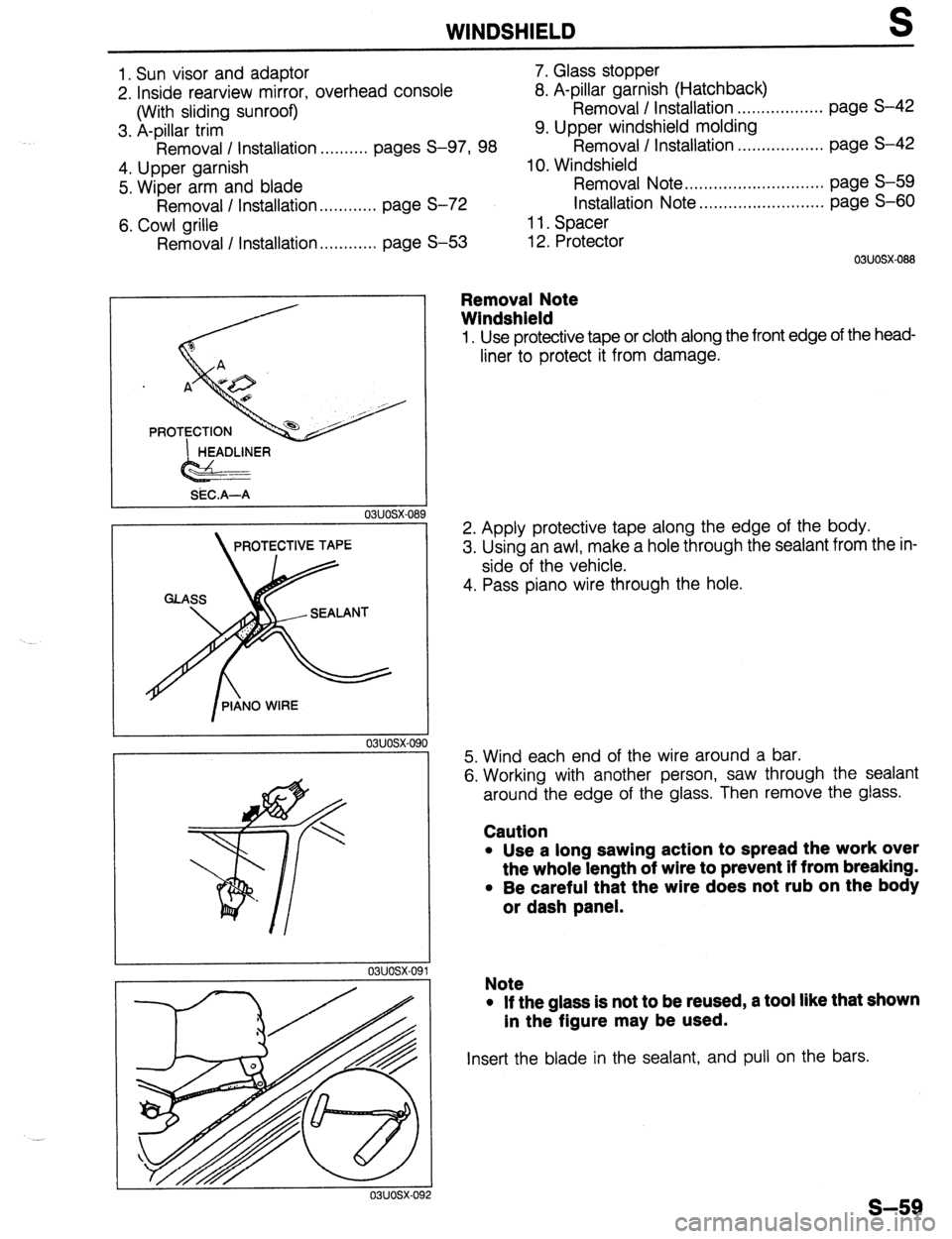
WINDSHIELD S
1. Sun visor and adaptor 7. Glass stopper
2. Inside rearview mirror, overhead console 8. A-pillar garnish (Hatchback)
(With sliding sunroof) Removal / Installation . . . . . . . . . . . . . . . . . . page S-42
3. A-pillar trim 9. Upper windshield molding
Removal / Installation ..,.,..... pages S-97, 98 Removal / Installation . . . . . . . . . . . . . . . . . . page S-42
4. Upper garnish 10. Windshield
5. Wiper arm and blade Removal Note .,.....*.........*........... page S-59
Removal / Installation . . . . . . . . . . . . page S-72 Installation Note ..,......*................ page S-60
6. Cowl arille 11. Spacer
Removal I Installation . . . . . . . . . . . . page S-53 12. Protector
1 HEADLINER
Gsi?i==
SiX.A-A
03uosx-08
PROTECTIVE TAPE -I
9 03UOSX-088
Removal Note
Windshield
1, Use protective tape or cloth along the front edge of the head-
liner to protect it from damage.
2. Apply protective tape along the edge of the body.
3. Using an awl, make a hole through the sealant from the in-
side of the vehicle.
4. Pass piano wire through the hole.
5. Wind each end of the wire around a bar.
6. Working with another person, saw through the sealant
around the edge of the glass. Then remove the glass.
Caution
l Use a long sawing action to spread the work over
the whole length of wire to prevent if from breaking.
l Be careful that the wire does not rub on the body
or dash panel.
Note
l If the glass is not to be reused, a tool like that shown
in the figure may be used.
Insert the blade in the sealant, and pull on the bars.
s-59