1989 MAZDA 323 horn
[x] Cancel search: hornPage 879 of 1164
SWITCHES T
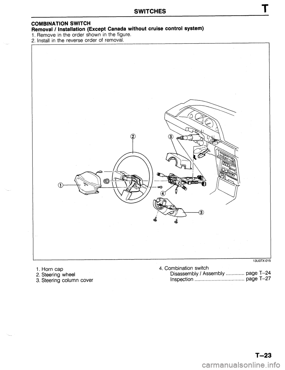
COMBINATION SWITCH
Removal / Installation (Except Canada without cruise control system)
1. Remove in the order shown in the figure.
2. Install in the reverse order of removal.
1. Horn cap
2. Steering wheel
3. Steering column cover 4. Combination switch
Disassembly I Assembly , . , . . . . . . . . . . page T-24
Inspection .,......,.,....,.*..*..,.,......... page T-27
T-23
Page 881 of 1164
SWITCHES T
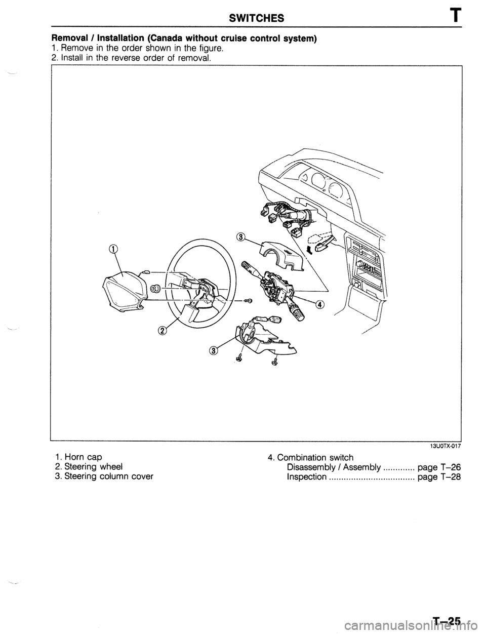
Removal / Installation (Canada without cruise control system)
1. Remove in the order shown in the figure.
2. Install in the reverse order of removal.
1. Horn cap
2. Steering wheel
3. Steering column cover 4. Combination switch
13UOTX-01;
Disassembly / Assembly . . . . . . . . . . . . . page T-26
Inspection . . , . . . . . . . . . . . . . . . . . . . . . . . . . . . ,. . , . page T-28
T-25
Page 942 of 1164
I
CRUISE CONTROL SYSTEM
s q 0 m
9 e c a
t rpn i j
h
f d b
*
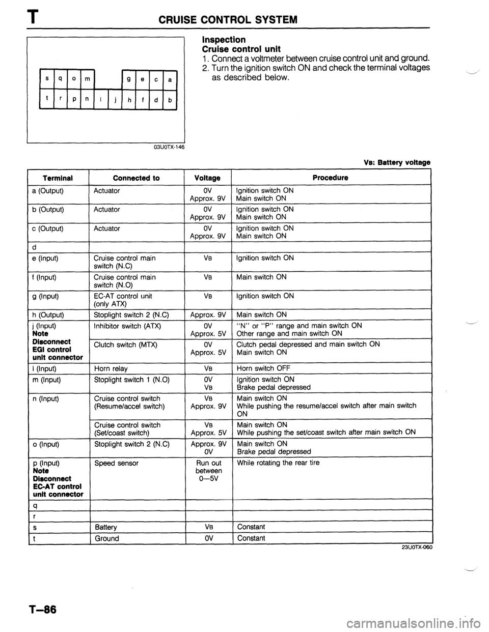
Inspection
Cruise control unit
1. Connect a voltmeter between cruise control unit and ground.
2. Turn the ignition switch ON and check the terminal voltages
as described below.
03UOTX-146
VB: Batterv voltage
c (Output) Actuator
I ov
Approx. 9V
e (Input)
I Cruise control main
I
VB switch (NC)
f (Input)
9 Wv-4 Cruise control main
switch (N.0)
EC-AT control unit
VB
V0
h (Output) (only ATX)
Stoplight switch 2 (N.C) Approx. 9V
i (hW Note I
Inhibitor switch (ATX)
I ov
Approx. 5V Disconnect t
EGI control
Clutch switch (MTX)
ov unit connector Approx. 5V
Cruise control switch
(Set/coast switch) V0
Approx. 5V unit connector
a
S I Battery
I VI3 t
1 Ground I ov Procedure
Ignition switch ON
Main switch ON
Ignition switch ON
Main switch ON
ignition switch ON
Main switch ON
Ignition switch ON
Main switch ON
Ignition switch ON
Main switch ON
“N” or “P” range and main switch ON
Other range and main switch ON
Clutch pedal depressed and main switch ON
Main switch ON
Horn switch OFF
Ignition switch ON
Brake pedal depressed
Main switch ON
While pushing the resumelaccel switch after main switch
ON
Main switch ON
While pushing the set/coast switch after main switch ON
Main switch ON
Brake pedal depressed
While rotating the rear tire
Constant
Constant
23UOTX-OE $0
‘,.__,
_ _-_,’
T-86
Page 944 of 1164
T HORN
HORN
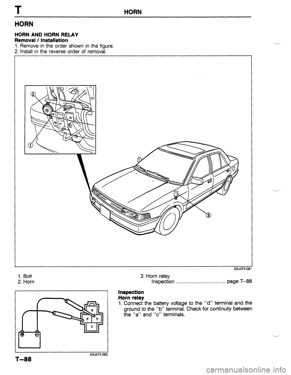
HORN AND HORN RELAY
Removal / Installation
1. Remove in the order shown in the figure.
2. Install in the reverse order of removal.
23UOTX-06
1. Bolt
2. Horn
I I
23UOTX-06
3. Horn relay
Inspection . . . . . . . . . . . . . . . . . . . ..*...**........ page T-88
Inspection
Horn relay
1. Connect the battery voltage to the “d” terminal and the
ground to the “b” terminal. Check for continuity between
the “a” and “c” terminals.
T-88
Page 1050 of 1164
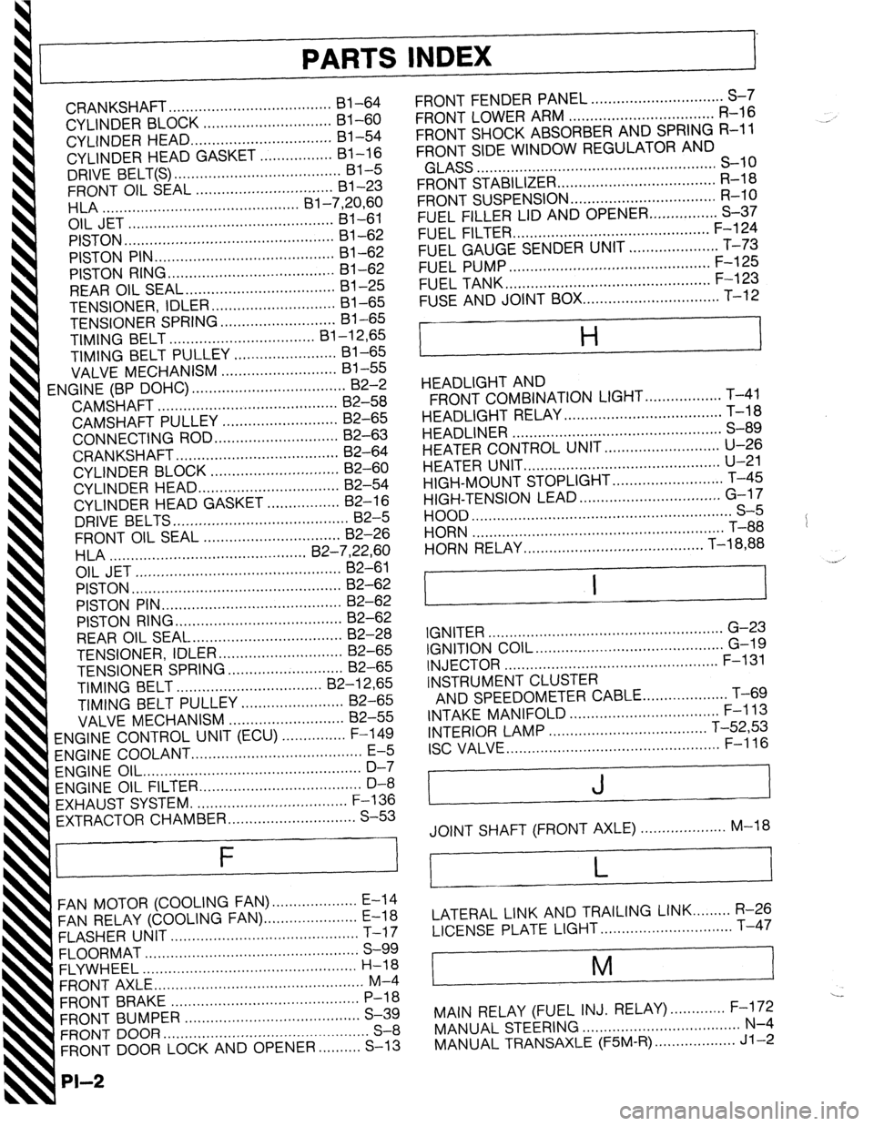
PARTS INDEX
I
CRANKSHAFT.. ....................................
I31 -64
CYLINDER BLOCK .............................. 61-60
CYLINDER HEAD..
............................... 81-54
CYLINDER HEAD GASKET .................
Bl-16
DRIVE BELT(S). ...................................... 81-5
FRONT OIL SEAL ................................ 81-23
HLA .............................................. Bl-7,20,60
OIL JET ................................................ 81-61
PISTON.. ...............................................
Bl-62
PISTON PIN..
........................................ 81-62
PISTON RING
....................................... 81-62
REAR
OIL SEAL..
................................. 81-25
TENSIONER, IDLER ............................. Bl-65
TENSIONER
SPRING ...........................
Bl-65
TIMING BELT ..................................
Bl-12,65
TIMING BELT PULLEY ........................
Bl-65
VALVE MECHANISM ........................... Bl-55
ENGINE
(BP DOHC) .................................... B2-2
CAMSHAFT ..........................................
82-58
CAMSHAFT PULLEY ...........................
B2-65
CONNECTING ROD..
........................... 82-63
CRANKSHAFT ......................................
B2-64
CYLINDER BLOCK ..............................
82-60
CYLINDER
HEAD.. ............................... B2-54
CYLINDER HEAD GASKET .................
82-16
DRIVE
BELTS.. .......................................
B2-5
FRONT
OIL SEAL ................................
82-26
H LA ..............................................
OIL JET .......................... B2-7iyL;;
......................
PISTON .................................................
B2-62
PISTON PIN ..........................................
82-62
PISTON RING..
..................................... 82-62
REAR OIL SEAL ................................... B2-28
TENSIONER, IDLER ............................. B2-65
TENSIONER SPRING ........................... B2-65
TIMING
BELT.. ................................
B2-12,65
TIMING BELT PULLEY ........................ 82-65
VALVE MECHANISM ........................... 82-55
ENGINE CONTROL UNIT (ECU) ............... F-149
ENGINE COOLANT
........................................ E-5
ENGINE OIL.. .................................................
D-7
ENGINE OIL FILTER.. .................................... D-8
’ EXHAUST SYSTEM. ...................................
F-136
EXTRACTOR CHAMBER .............................. S-53
F
FAN MOTOR (COOLING FAN). ................... E-14
FAN RELAY (COOLING FAN). ..................... E-18
FLASHER UNIT ............................................
T-17
FLOORMAT ..................................................
S-99
FLYWHEEL ..................................................
H-18
FRONT AXLE .................................................
M-4
FRONT BRAKE ............................................
P-l 8
FRONT BUMPER ......................................... S-39
FRONT DOOR ................................................
S-8
FRONT DOOR LOCK AND OPENER ..........
S-13
PI-2
FRONT FENDER PANEL ............................... S-7
FRONT LOWER ARM .................................. R-16
FRONT SHOCK ABSORBER AND SPRING R-11
FRONT SIDE WINDOW REGULATOR AND
GLASS ........................................................ S-10
FRONT STABILIZER..
................................... R-l 8
FRONT SUSPENSION .................................. R-l 0
FUEL FILLER LID AND OPENER..
.............. S-37
FUEL FILTER .............................................. F-l 24
FUEL GAUGE SENDER UNIT ..................... T-73
FUEL PUMP ............................................... F-125
FUEL TANK
................................................ F-123
FUSE AND JOINT BOX.. .............................. T-12
H
HEADLIGHT AND
FRONT COMBINATION LIGHT..
................ T-41
HEADLIGHT RELAY ..................................... T-l 8
HEADLINER ................................................. S-89
HEATER CONTROL UNIT.. ......................... U-26
HEATER UNIT
.............................................. U-21
HIGH-MOUNT STOPLIGHT
.......................... T-45
HIGH-TENSION LEAD ................................. G-l 7
HOOD ............................................................. S-5
HORN T-88
...........................................................
HORN RELAY
.......................................... T-18,88
.__. ’
I I
IGNITER .......................................................
G-23
IGNITION COIL.. .......................................... G-19
INJECTOR .................................................. F-l 31
INSTRUMENT CLUSTER
AND SPEEDOMETER CABLE
.................... T-69
INTAKE MANIFOLD ................................... F-113
INTERIOR LAMP ..................................... T-52,53
ISC VALVE.. ................................................ F-l 16
J
JOINT SHAFT (FRONT AXLE) .................... M-18
L
LATERAL LINK AND TRAILING LINK.. ....... R-26
LICENSE PLATE LIGHT.. ............................. T-47
i
M
I
---
MAIN RELAY (FUEL INJ. RELAY). ............ F-172
MANUAL STEERING ..................................... N-4
MANUAL TRANSAXLE (F5M-R). .................. Jl-2
Page 1055 of 1164
Z
SYSTEM INDEX
System Section System Section
AUDIO SYSTEM ......................................................... J
BACK-UP LIGHTS ...................................................
F-3
CHARGING SYSTEM ............................................... A-2
CIGARETTE LIGHTER ............................................... I-1
COMMON CONNECTOR LIST ..................................... X
COOLING FAN SYSTEM ....................................... B-3.4
COURTESY LAMPS .................................................. l-3
CRUISE CONTROL SYSTEM ...................................... Q
DAYTIME RUNNING UGHTS .................................... E-3
DIAGNOSIS CONNECTOR .......................................... U
DIGITAL CLOCK ....................................................... l-l
ELECTRICAL WIRING SCHEMATIC ............................. W
ENGINE CONTROL SYSTEM (MT) ................. B-l a, 1 b, 1 c
ENGINE 8 EC-AT CONTROL
SYSTEM (EC-AT) ...................................... B-2a,2b,2c
GENERAL INFORMATION .......................................... GI
GROUND POINT ........................................................ Y
HEADLIGHTS ....................................................... E-l ,2
HEATER 8 AIR CONDITIONER .................................... G
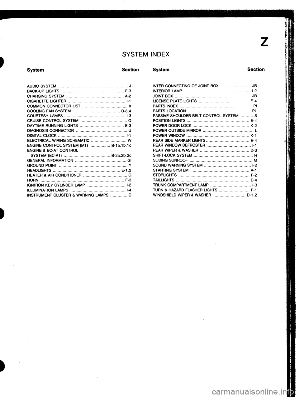
HORN .................................................................... F-3
IGNITION KEY CYLINDER LAMP ............................... l-2
ILLUMINATION LAMPS .............................................
l-4
INSTRUMENT CLUSTER . WARNING LAMPS .............. C INTER CONNECTING OF JOINT BOX ......................... JB
INTERIOR LAMP ...................................................... l-2
JOINT BOX .............................................................. JB
LICENSE PLATE UGHTS ......................................... E-4
PARTS INDEX ........................................................... PI
PARTS LOCATION ................................................... PL
PASSIVE SHOULDER BELT CONTROL SYSTEM .......... S
POSITION LIGHTS ................................................... E-4
POWER DOOR LOCK ............................................. K-2
POWER OUTSIDE MIRROR ......................................... L
POWER WINDOW ................................................... K-l
REAR SIDE MARKER LIGHTS.. ................................. E-4
REAR WINDOW DEFROSTER .................................... I-1
REAR WIPER 8 WASHER ........................................ D-3
SHIFT-LOCK SYSTEM ................................................ H
SLIDING SUNROOF ................................................... M
SOUND WARNING SYSTEM ...................................... l-2
STARTING SYSTEM ................................................ A-l
STOPLIGHTS .......................................................... F-2
TAILLIGHTS ............................................................ E-4
TRUNK COMPARTMENT LAMP ................................. l-3
TURN 8 HAZARD FLASHER UGHTS ......................... F-l
WINDSHIELD WIPER 8 WASHER .......................... D-l ,2
Page 1061 of 1164
Reading Wiring Diagrams Z-GI-5
System name
SYSTEM l FUEL INJECTION SYSTEM f
B-lc py,p -
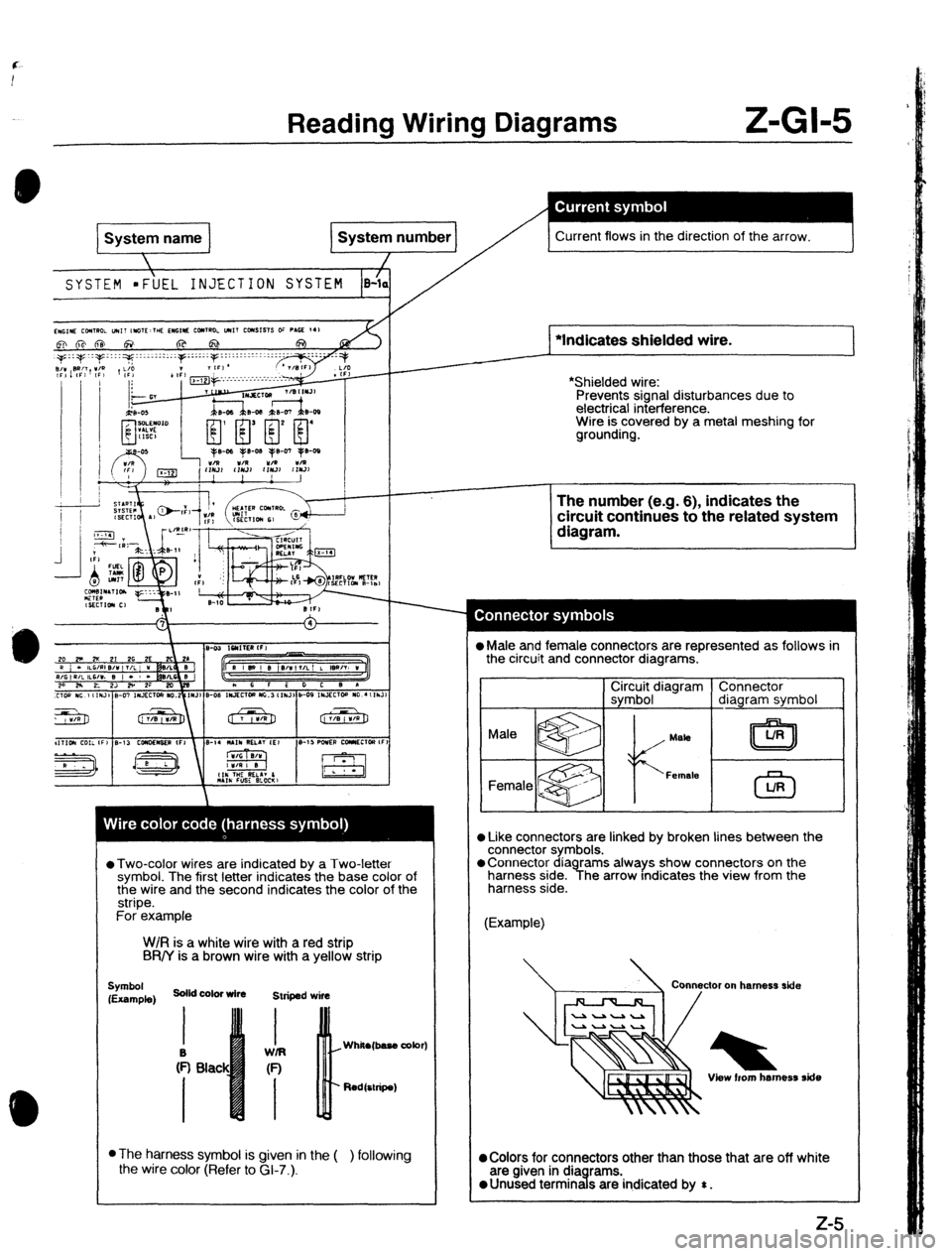
Current flows in the direction of the arrow.
L
::::y...:::..: ::::;IF::::::I::::.:I:I~-. I :I::- .::
F
~~-;..~~~-~-~~~-~-~-~-~-~~~~~-:~-. t /
*Indicates shielded wire.
*Shielded wire:
Prevents signal disturbances due to
electrical interference.
Wire is covered by a metal meshing for
grounding.
*Two-color wires are indicated by a Two-letter
symbol. The first letter indicates the base color of
the wire and the second indicates the color of the
stripe.
For example
W/R is a white wire with a red strip
BR/Y is a brown wire with a yellow strip
Symbol
(Example) solid color wire
Striped wire
Red&ripe)
l
The harness symbol is given in the (
the wire color (Refer to GI-7.). ) following The number (e.g. 6), indicates the
circuit continues to the related system
diagram.
0 Male and female connectors are represented as follows in
the circuit and connector diagrams.
C3r3r;$,diagram
l Like connectors are linked by broken lines between the
connector symbols.
oconnector diagrams always show connectors on the
harness side. The arrow Indicates the view from the
harness side.
(Example)
View horn harness ride
@Colors for connectors other than those that are off white
are given in dia rams.
0 Unused termrn d s are
indicated by $ .
Page 1065 of 1164
Reading Wiring Diagrams Z-GI-9
Symbol ‘ Meaning Symbol Meaning
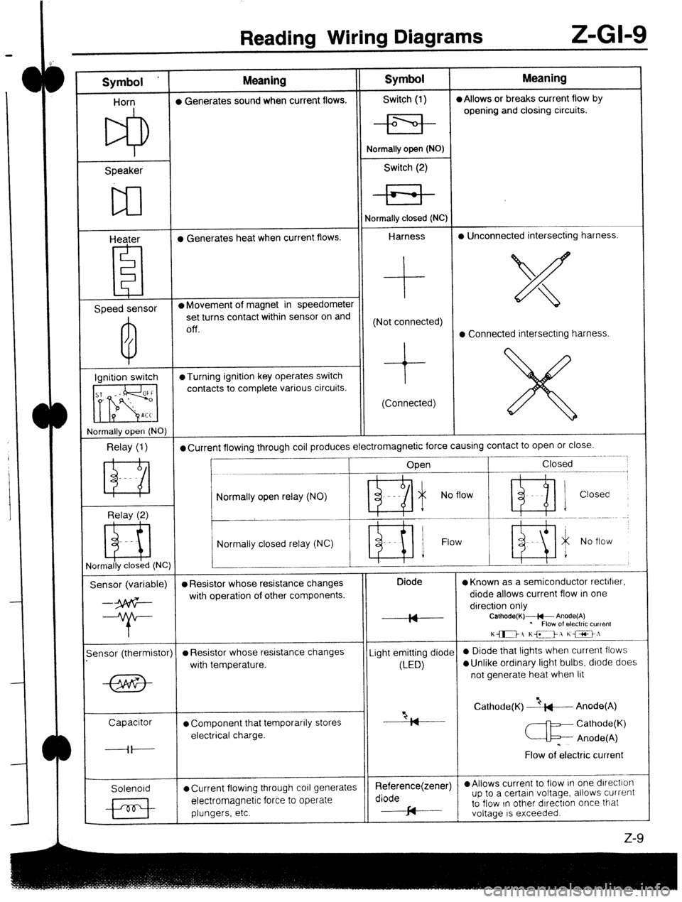
Horn l Generates sound when current flows. Switch (1) l Allows or breaks current flow by
opening and closing circuits.
Speaker
w
Heater l Generates heat when current flows. Normally open (NO)
Switch (2)
Normally closed (NC)
Harness l Unconnected intersecting harness.
Speed sensor l Movement of magnet in speedometer
set turns contact within sensor on and
Off. (Not connected)
l Connected intersecting harness.
Ignition switch @Turning ignition key operates switch
contacts to complete various circuits.
(Connected)
rlormally open (NO)
Relay (1) l Current flowing through coil produces electromagnetic force causing contact to open or close.
____- .~.~~
Open Closed
--.--.-m.---------,
Relay (2) Normally open relay (NO)
- Ri i No flow ’ ni 1 Closed
Normally closed relay (NC) Flow
ormally closed (NC)
Sensor (variable) l Resistor whose resistance changes Diode
l Known as a semiconductor rectifier.
--3p6G- with operation of other components. diode allows current flow in one
direction only
--T- IA
IY Calhode(K)+- Anode(A)
* Flow of electric current
K-1 KD, he>:
-
ensor (thermistor)
l Resistor whose resistance changes Light emitting diode 0 Diode that lights when current flows
with temperature.
(LED)
l Unlike ordinary light bulbs, diode does
not generate heat when lit
Capacitor
l Component that temporarily stores “2, Cathode(K) --&---Anode(A)
I7
Cathode(K)
electrical charge.
c Anode(A)
----il---- .
Flow of electric current
Solenoid
l Current flowing through co11 generates Reference(zener) l Allows current to flow In one dlrectlon
electromagnetic force to operate diode up to a certain voltage. allows current
plungers, etc. cd to flow In other dIrectron once that
J-
voltage IS exceeded.
z-9