1988 OPEL VECTRA belt
[x] Cancel search: beltPage 225 of 525
18If the engine is in the vehicle, further
refitting is a reversal of the removal
procedure, but refit the front section of the
exhaust system referring to Chapter 4C. On
completion, refill the engine with oil, as
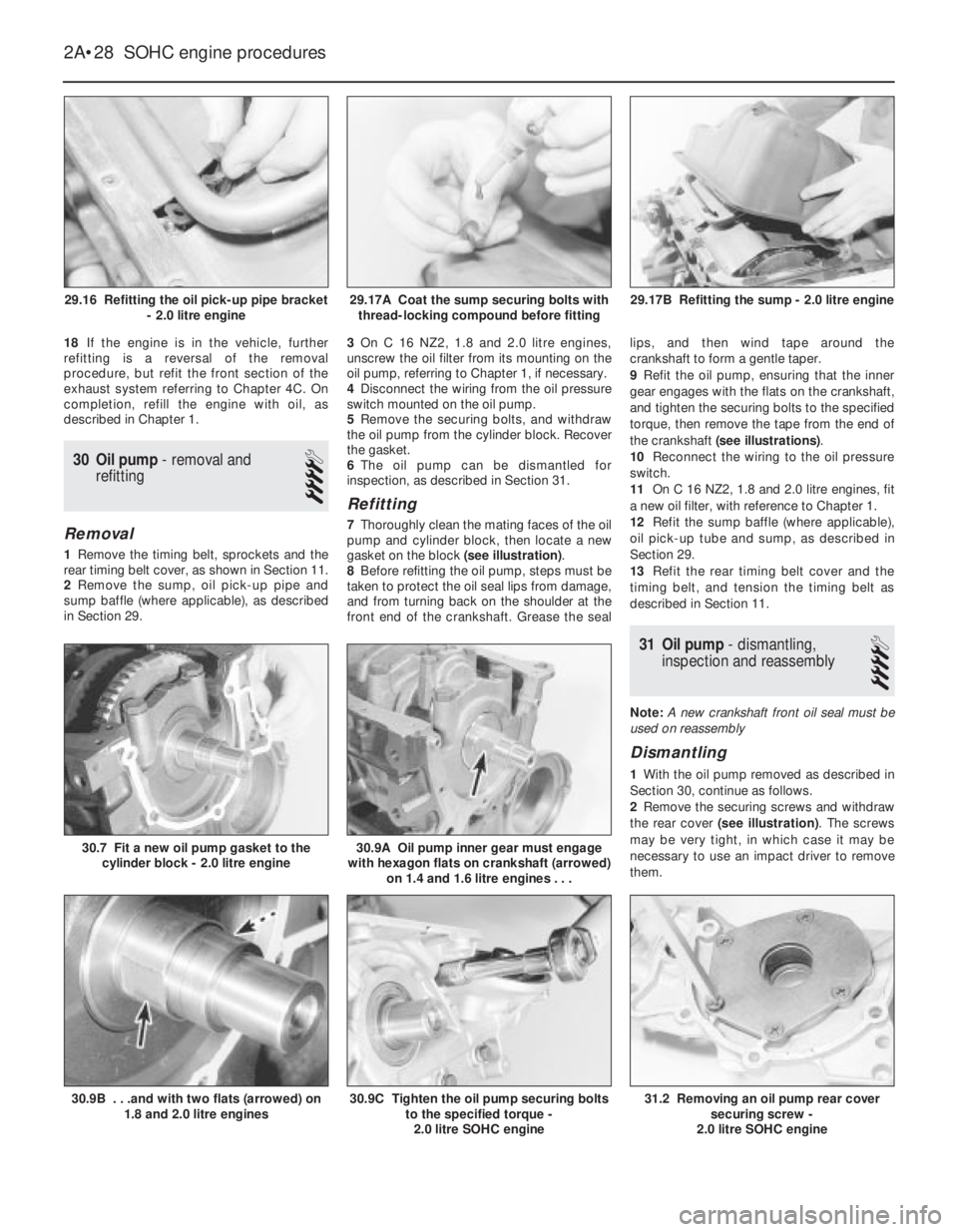
described in Chapter 1.
30Oil pump - removal and
refitting
4
Removal
1Remove the timing belt, sprockets and the
rear timing belt cover, as shown in Section 11.
2Remove the sump, oil pick-up pipe and
sump baffle (where applicable), as described
in Section 29.3On C 16 NZ2, 1.8 and 2.0 litre engines,
unscrew the oil filter from its mounting on the
oil pump, referring to Chapter 1, if necessary.
4Disconnect the wiring from the oil pressure
switch mounted on the oil pump.
5Remove the securing bolts, and withdraw
the oil pump from the cylinder block. Recover
the gasket.
6The oil pump can be dismantled for
inspection, as described in Section 31.
Refitting
7Thoroughly clean the mating faces of the oil
pump and cylinder block, then locate a new
gasket on the block (see illustration).
8Before refitting the oil pump, steps must be
taken to protect the oil seal lips from damage,
and from turning back on the shoulder at the
front end of the crankshaft. Grease the seallips, and then wind tape around the
crankshaft to form a gentle taper.
9Refit the oil pump, ensuring that the inner
gear engages with the flats on the crankshaft,
and tighten the securing bolts to the specified
torque, then remove the tape from the end of
the crankshaft (see illustrations).
10Reconnect the wiring to the oil pressure
switch.
11On C 16 NZ2, 1.8 and 2.0 litre engines, fit
a new oil filter, with reference to Chapter 1.
12Refit the sump baffle (where applicable),
oil pick-up tube and sump, as described in
Section 29.
13Refit the rear timing belt cover and the
timing belt, and tension the timing belt as
described in Section 11.
31Oil pump - dismantling,
inspection and reassembly
4
Note: A new crankshaft front oil seal must be
used on reassembly
Dismantling
1With the oil pump removed as described in
Section 30, continue as follows.
2Remove the securing screws and withdraw
the rear cover (see illustration). The screws
may be very tight, in which case it may be
necessary to use an impact driver to remove
them.
2A•28SOHC engine procedures
29.16 Refitting the oil pick-up pipe bracket
- 2.0 litre engine29.17B Refitting the sump - 2.0 litre engine
31.2 Removing an oil pump rear cover
securing screw -
2.0 litre SOHC engine30.9C Tighten the oil pump securing bolts
to the specified torque -
2.0 litre SOHC engine30.9B . . .and with two flats (arrowed) on
1.8 and 2.0 litre engines
30.9A Oil pump inner gear must engage
with hexagon flats on crankshaft (arrowed)
on 1.4 and 1.6 litre engines . . .30.7 Fit a new oil pump gasket to the
cylinder block - 2.0 litre engine
29.17A Coat the sump securing bolts with
thread-locking compound before fitting
Page 227 of 525
14Insert the rod and piston into the top of
the cylinder bore, so that the base of the
compressor stands on the block. Check that
the connecting rod markings are towards the
side of the engine noted during removal. Note
that the arrow or notch, as applicable, on the
piston crown should point towards the timing
belt end of the engine, and the lugs on the
connecting rods should point towards the
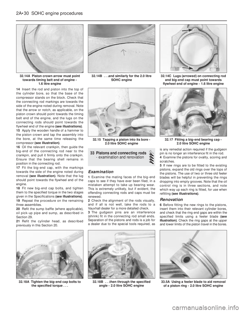
flywheel end of the engine (see illustrations).
15Apply the wooden handle of a hammer to
the piston crown and tap the assembly into
the bore, at the same time releasing the
compressor (see illustration).
16Oil the relevant crankpin, then guide the
big-end of the connecting rod near to the
crankpin, and pull it firmly onto the crankpin.
Ensure that the bearing shell remains in
position in the connecting rod.
17Fit the big-end cap, with the markings
towards the side of the engine noted during
removal (see illustration). Note that the lug
should point towards the flywheel end of the
engine.
18Fit new big-end cap bolts, and tighten
them to the specified torque in the two stages
given in the Specifications (see illustrations).
19Repeat the procedure on the remaining
three assemblies.
20Refit the sump baffle (where applicable),
oil pick-up pipe and sump, as described in
Section 29.
21Refit the cylinder head, as described
previously in this Section 20.
33Pistons and connecting rods
-examination and renovation
4
Examination
1Examine the mating faces of the big-end
caps to see if they have ever been filed, in a
mistaken attempt to take up bearing wear.
This is extremely unlikely, but if evident, the
offending connecting rods and caps must be
renewed.
2Check the alignment of the rods visually,
and if all is not well, take the rods to a
Vauxhall dealer for a more detailed check.
3The gudgeon pins are an interference
(shrink) fit in the connecting rod small ends.
Separation of the pistons and rods is a job for
a dealer due to the special tools required, asis any remedial action required if the gudgeon
pin is no longer an interference fit in the rod.
4Examine the pistons for ovality, scoring and
scratches.
5If new rings are to be fitted to the existing
pistons, expand the old rings over the tops of
the pistons. The use of two or three old feeler
blades will be helpful in preventing the rings
dropping into empty grooves. Note that the oil
control ring is in three sections, and note
which way up each ring is fitted, for use when
refitting (see illustrations).
Renovation
6Before fitting the new rings to the pistons,
insert them into their relevant cylinder bores,
and check that the ring end gaps are within the
specified limits using a feeler blade (see
illustration). Check the ring gaps at the upper
and lower limits of the piston travel in the bores.
2A•30SOHC engine procedures
32.14A Piston crown arrow must point
towards timing belt end of engine -
1.6 litre engine32.14C Lugs (arrowed) on connecting rod
and big-end cap must point towards
flywheel end of engine - 1.6 litre engine
33.5A Using a feeler blade to aid removal
of a piston ring - 2.0 litre SOHC engine32.18B . . .then through the specified
angle - 2.0 litre SOHC engine32.18A Tighten the big-end cap bolts to
the specified torque . . .
32.17 Fitting a big-end bearing cap -
2.0 litre SOHC engine32.15 Tapping a piston into its bore -
2.0 litre SOHC engine
32.14B . . .and similarly for the 2.0 litre
SOHC engine
Page 228 of 525
7If any of the ring end gaps exceed the
specified tolerance, the relevant rings will have
to be renewed, and if the ring grooves in the
pistons are worn, new pistons may be required.
8Clean out the piston ring grooves using a
piece of old piston ring as a scraper. Take
care not to scratch the surface of the pistons.
Protect your fingers, piston ring edges are
sharp. Also probe the groove oil return holes,
to ensure that they are not blocked.
9Check the cylinder bores for signs of wear
ridges towards the top of the bores. If wear
ridges are evident, and new piston rings are
being fitted, the top ring must be stepped to
clear the wear ridge, or the bore must be
de-ridged using a scraper.
10Fit the oil control ring sections with the
lower steel ring gap offset 25 to 50 mm to the
right of the spreader ring gap, and the upper
steel ring gap offset by the same distance to
the left of the spreader ring gap.
11Fit the lower compression ring, noting that
the ring is tapered or stepped. The ring should
be fitted with the word “TOP” uppermost.
12Fit the upper compression ring, and offset
the ring gap by 180°to the lower compression
ring gap. If a stepped ring is being fitted, fit
the ring with the smaller diameter of the step
uppermost.
13If new pistons are to be fitted, they must
be selected from the grades available, after
measuring the cylinder bores as described in
Section 36.
14Normally the appropriate oversize pistons
are supplied by the dealer when the block is
rebored.15Whenever new piston rings are being
installed, the glaze on the original cylinder
bores should be “broken”, using either
abrasive paper or a glaze-removing tool in an
electric drill. If abrasive paper is used, use
strokes at 60°to the bore centre line, to create
a cross-hatching effect.
34Crankshaft and bearings -
removal and refitting
4
Note: New main bearing cap bolts must be
used on refitting
Removal
1With the engine removed from the vehicle,
continue as follows.
2Remove the cylinder head, as described
previously in Section 20.
3Remove the sump, oil pick-up pipe and
sump baffle (where applicable), as described
in Section 29.
4Remove the oil pump, as described in
Section 30.
5Remove the flywheel or flexplate (if
applicable), as described in Sections 25 and
26.
6Remove the pistons and connecting rods,
as described in Section 32.
7Invert the engine so that it is standing on
the top face of the cylinder block.
8The main bearing caps are numbered 1 to 4
from the timing belt end of the engine. The
rear (flywheel end) cap is not marked. Toensure that the caps are refitted the correct
way round, note that the numbers are read
from the coolant pump side of the engine with
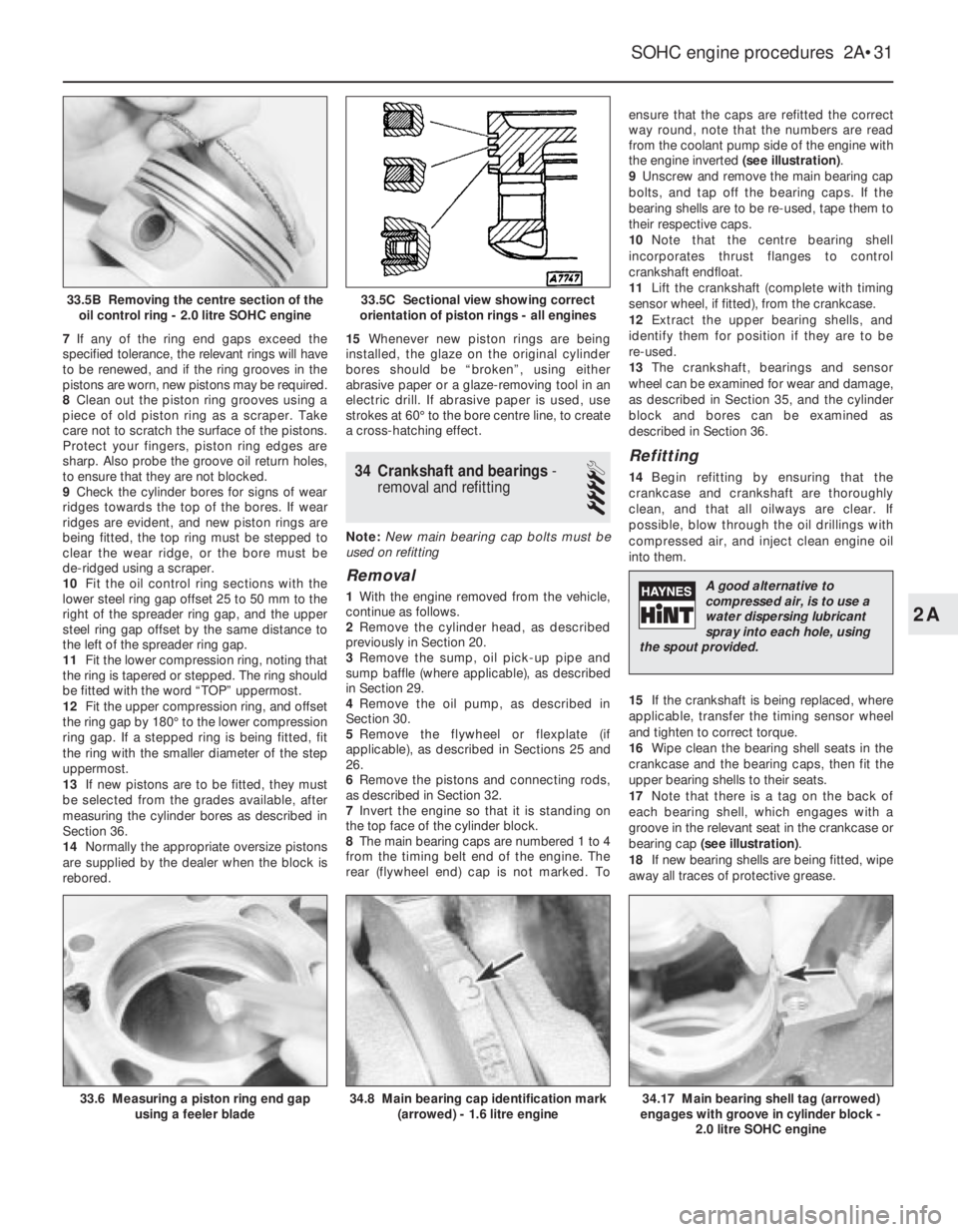
the engine inverted (see illustration).
9Unscrew and remove the main bearing cap
bolts, and tap off the bearing caps. If the
bearing shells are to be re-used, tape them to
their respective caps.
10Note that the centre bearing shell
incorporates thrust flanges to control
crankshaft endfloat.
11Lift the crankshaft (complete with timing
sensor wheel, if fitted), from the crankcase.
12Extract the upper bearing shells, and
identify them for position if they are to be
re-used.
13The crankshaft, bearings and sensor
wheel can be examined for wear and damage,
as described in Section 35, and the cylinder
block and bores can be examined as
described in Section 36.
Refitting
14Begin refitting by ensuring that the
crankcase and crankshaft are thoroughly
clean, and that all oilways are clear. If
possible, blow through the oil drillings with
compressed air, and inject clean engine oil
into them.
15If the crankshaft is being replaced, where
applicable, transfer the timing sensor wheel
and tighten to correct torque.
16Wipe clean the bearing shell seats in the
crankcase and the bearing caps, then fit the
upper bearing shells to their seats.
17Note that there is a tag on the back of
each bearing shell, which engages with a
groove in the relevant seat in the crankcase or
bearing cap (see illustration).
18If new bearing shells are being fitted, wipe
away all traces of protective grease.
SOHC engine procedures 2A•31
33.6 Measuring a piston ring end gap
using a feeler blade34.8 Main bearing cap identification mark
(arrowed) - 1.6 litre engine34.17 Main bearing shell tag (arrowed)
engages with groove in cylinder block -
2.0 litre SOHC engine
33.5C Sectional view showing correct
orientation of piston rings - all engines33.5B Removing the centre section of the
oil control ring - 2.0 litre SOHC engine
2A
A good alternative to
compressed air, is to use a
water dispersing lubricant
spray into each hole, using
the spout provided.
Page 232 of 525
3
System type . . . . . . . . . . . . . . . . . . . . . . . . . . . . . . . . . . . . . . . . . . . Pressurised, with remote expansion tank. Coolant pump driven by
timing belt
Coolant
Type/specification (all models) . . . . . . . . . . . . . . . . . . . . . . . . . . . . . . . . See Lubricants and fluidsin “Weekly checks”
Capacity . . . . . . . . . . . . . . . . . . . . . . . . . . . . . . . . . . . . . . . . . . . . . . . . . See Chapter 1 Specifications
Thermostat
Starts to open at (all models) . . . . . . . . . . . . . . . . . . . . . . . . . . . . . . . . . 92°C
Fully open at (all models) . . . . . . . . . . . . . . . . . . . . . . . . . . . . . . . . . . . . 107°C
Operating temperature (approx.) . . . . . . . . . . . . . . . . . . . . . . . . . . . . . . 80°C
Expansion tank cap
Opening pressure (all models) . . . . . . . . . . . . . . . . . . . . . . . . . . . . . . . . 1.20 to 1.35 bar
Boiling point . . . . . . . . . . . . . . . . . . . . . . . . . . . . . . . . . . . . . . . . . . . . . . 125°C
Cooling fan switch
Switches on at (all models) . . . . . . . . . . . . . . . . . . . . . . . . . . . . . . . . . . . 100°C
Switches off at (all models) . . . . . . . . . . . . . . . . . . . . . . . . . . . . . . . . . . . 95°C
Torque wrench settingsNm lbf ft
Coolant pump bolts:
1.4 and 1.6 litre models
(except C16 NZ2), (M6) . . . . . . . . . . . . . . . . . . . . . . . . . . . . . . . . . . 8 6
C16 NZ2, 1.8 and 2.0 litre models (M8) . . . . . . . . . . . . . . . . . . . . . . . 25 18
Oil pipes to radiator . . . . . . . . . . . . . . . . . . . . . . . . . . . . . . . . . . . . . . . . 22 16
Outlet to thermostat housing,
C16 NZ2, 1.8 and 2.0 litre models . . . . . . . . . . . . . . . . . . . . . . . . . . . 8 6
Temperature sender . . . . . . . . . . . . . . . . . . . . . . . . . . . . . . . . . . . . . . . . 10 7
Temperature sensor . . . . . . . . . . . . . . . . . . . . . . . . . . . . . . . . . . . . . . . . 11 8
Thermostat housing to cylinder head:
1.4 and 1.6 litre models (except C16 NZ2) . . . . . . . . . . . . . . . . . . . . . 10 7
C16 NZ2, 1.8 and 2.0 litre models . . . . . . . . . . . . . . . . . . . . . . . . . . . 15 11
Chapter 3
Cooling, heating and ventilation systems
Coolant mixture - general . . . . . . . . . . . . . . . . . . . . . . . . . . . . . . . . . . .5
Coolant pump - removal and refitting . . . . . . . . . . . . . . . . . . . . . . . . .11
Cooling fan - removal and refitting . . . . . . . . . . . . . . . . . . . . . . . . . . .12
Cooling fan switch - removal and refitting . . . . . . . . . . . . . . . . . . . . .15
Cooling system - draining . . . . . . . . . . . . . . . . . . . . . . . . . . . . . . . . . . .2
Cooling system - filling . . . . . . . . . . . . . . . . . . . . . . . . . . . . . . . . . . . . .4
Cooling system - flushing . . . . . . . . . . . . . . . . . . . . . . . . . . . . . . . . . . .3
Expansion tank and coolant level sensor - removal and refitting . . . .13
Facia ventilation nozzles - removal and refitting . . . . . . . . . . . . . . . .19
General description . . . . . . . . . . . . . . . . . . . . . . . . . . . . . . . . . . . . . . .1Heater blower motor - removal and refitting . . . . . . . . . . . . . . . . . . .18
Heater control panel - removal and refitting . . . . . . . . . . . . . . . . . . . .16
Heater matrix - removal and refitting . . . . . . . . . . . . . . . . . . . . . . . . .17
Radiator (automatic transmission) - removal and refitting . . . . . . . . . .7
Radiator (manual transmission) - removal and refitting . . . . . . . . . . . .6
Radiator - inspection and cleaning . . . . . . . . . . . . . . . . . . . . . . . . . . . .8
Temperature gauge sender - removal and refitting . . . . . . . . . . . . . .14
Thermostat - removal and refitting . . . . . . . . . . . . . . . . . . . . . . . . . . . .9
Thermostat - testing . . . . . . . . . . . . . . . . . . . . . . . . . . . . . . . . . . . . . .10
3•1
Specifications Contents
Easy,suitable for
novice with little
experienceFairly easy,suitable
for beginner with
some experienceFairly difficult,
suitable for competent
DIY mechanic
Difficult,suitable for
experienced DIY
mechanicVery difficult,
suitable for expert DIY
or professional
Degrees of difficulty
54321
Page 233 of 525
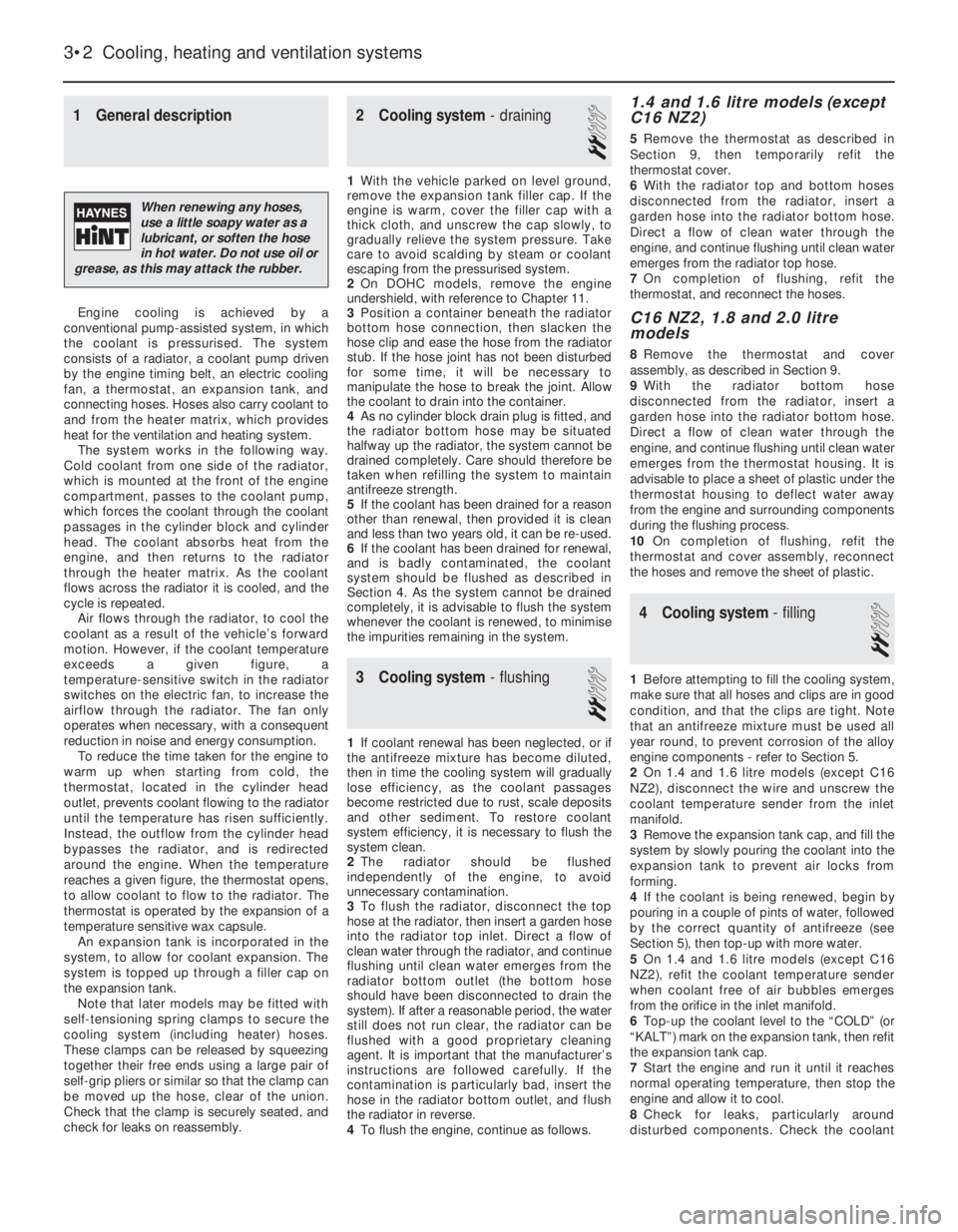
1General description
Engine cooling is achieved by a
conventional pump-assisted system, in which
the coolant is pressurised. The system
consists of a radiator, a coolant pump driven
by the engine timing belt, an electric cooling
fan, a thermostat, an expansion tank, and
connecting hoses. Hoses also carry coolant to
and from the heater matrix, which provides
heat for the ventilation and heating system.
The system works in the following way.
Cold coolant from one side of the radiator,
which is mounted at the front of the engine
compartment, passes to the coolant pump,
which forces the coolant through the coolant
passages in the cylinder block and cylinder
head. The coolant absorbs heat from the
engine, and then returns to the radiator
through the heater matrix. As the coolant
flows across the radiator it is cooled, and the
cycle is repeated.
Air flows through the radiator, to cool the
coolant as a result of the vehicle’s forward
motion. However, if the coolant temperature
exceeds a given figure, a
temperature-sensitive switch in the radiator
switches on the electric fan, to increase the
airflow through the radiator. The fan only
operates when necessary, with a consequent
reduction in noise and energy consumption.
To reduce the time taken for the engine to
warm up when starting from cold, the
thermostat, located in the cylinder head
outlet, prevents coolant flowing to the radiator
until the temperature has risen sufficiently.
Instead, the outflow from the cylinder head
bypasses the radiator, and is redirected
around the engine. When the temperature
reaches a given figure, the thermostat opens,
to allow coolant to flow to the radiator. The
thermostat is operated by the expansion of a
temperature sensitive wax capsule.
An expansion tank is incorporated in the
system, to allow for coolant expansion. The
system is topped up through a filler cap on
the expansion tank.
Note that later models may be fitted with
self-tensioning spring clamps to secure the
cooling system (including heater) hoses.
These clamps can be released by squeezing
together their free ends using a large pair of
self-grip pliers or similar so that the clamp can
be moved up the hose, clear of the union.
Check that the clamp is securely seated, and
check for leaks on reassembly.
2Cooling system -draining
2
1With the vehicle parked on level ground,
remove the expansion tank filler cap. If the
engine is warm, cover the filler cap with a
thick cloth, and unscrew the cap slowly, to
gradually relieve the system pressure. Take
care to avoid scalding by steam or coolant
escaping from the pressurised system.
2On DOHC models, remove the engine
undershield, with reference to Chapter 11.
3Position a container beneath the radiator
bottom hose connection, then slacken the
hose clip and ease the hose from the radiator
stub. If the hose joint has not been disturbed
for some time, it will be necessary to
manipulate the hose to break the joint. Allow
the coolant to drain into the container.
4As no cylinder block drain plug is fitted, and
the radiator bottom hose may be situated
halfway up the radiator, the system cannot be
drained completely. Care should therefore be
taken when refilling the system to maintain
antifreeze strength.
5If the coolant has been drained for a reason
other than renewal, then provided it is clean
and less than two years old, it can be re-used.
6If the coolant has been drained for renewal,
and is badly contaminated, the coolant
system should be flushed as described in
Section 4. As the system cannot be drained
completely, it is advisable to flush the system
whenever the coolant is renewed, to minimise
the impurities remaining in the system.
3Cooling system -flushing
2
1If coolant renewal has been neglected, or if
the antifreeze mixture has become diluted,
then in time the cooling system will gradually
lose efficiency, as the coolant passages
become restricted due to rust, scale deposits
and other sediment. To restore coolant
system efficiency, it is necessary to flush the
system clean.
2The radiator should be flushed
independently of the engine, to avoid
unnecessary contamination.
3To flush the radiator, disconnect the top
hose at the radiator, then insert a garden hose
into the radiator top inlet. Direct a flow of
clean water through the radiator, and continue
flushing until clean water emerges from the
radiator bottom outlet (the bottom hose
should have been disconnected to drain the
system). If after a reasonable period, the water
still does not run clear, the radiator can be
flushed with a good proprietary cleaning
agent. It is important that the manufacturer’s
instructions are followed carefully. If the
contamination is particularly bad, insert the
hose in the radiator bottom outlet, and flush
the radiator in reverse.
4To flush the engine, continue as follows.
1.4 and 1.6 litre models (except
C16 NZ2)
5Remove the thermostat as described in
Section 9, then temporarily refit the
thermostat cover.
6With the radiator top and bottom hoses
disconnected from the radiator, insert a
garden hose into the radiator bottom hose.
Direct a flow of clean water through the
engine, and continue flushing until clean water
emerges from the radiator top hose.
7On completion of flushing, refit the
thermostat, and reconnect the hoses.
C16 NZ2, 1.8 and 2.0 litre
models
8Remove the thermostat and cover
assembly, as described in Section 9.
9With the radiator bottom hose
disconnected from the radiator, insert a
garden hose into the radiator bottom hose.
Direct a flow of clean water through the
engine, and continue flushing until clean water
emerges from the thermostat housing. It is
advisable to place a sheet of plastic under the
thermostat housing to deflect water away
from the engine and surrounding components
during the flushing process.
10On completion of flushing, refit the
thermostat and cover assembly, reconnect
the hoses and remove the sheet of plastic.
4Cooling system -filling
2
1Before attempting to fill the cooling system,
make sure that all hoses and clips are in good
condition, and that the clips are tight. Note
that an antifreeze mixture must be used all
year round, to prevent corrosion of the alloy
engine components -refer to Section 5.
2On 1.4 and 1.6 litre models (except C16
NZ2), disconnect the wire and unscrew the
coolant temperature sender from the inlet
manifold.
3Remove the expansion tank cap, and fill the
system by slowly pouring the coolant into the
expansion tank to prevent air locks from
forming.
4If the coolant is being renewed, begin by
pouring in a couple of pints of water, followed
by the correct quantity of antifreeze (see
Section 5), then top-up with more water.
5On 1.4 and 1.6 litre models (except C16
NZ2), refit the coolant temperature sender
when coolant free of air bubbles emerges
from the orifice in the inlet manifold.
6Top-up the coolant level to the “COLD” (or
“KALT”) mark on the expansion tank, then refit
the expansion tank cap.
7Start the engine and run it until it reaches
normal operating temperature, then stop the
engine and allow it to cool.
8Check for leaks, particularly around
disturbed components. Check the coolant
3•2Cooling, heating and ventilation systems
When renewing any hoses,
use a little soapy water as a
lubricant, or soften the hose
in hot water. Do not use oil or
grease, as this may attack the rubber.
Page 235 of 525
8Radiator -inspection and
cleaning
2
1If the radiator has been removed due to
suspected blockage, reverse-flush it as
described in Section 3.
2Clean dirt and debris from the radiator fins,
using an air jet or a soft brush. Take care, as
the fins are easily damaged and are sharp.
3If necessary, a radiator specialist can
perform a “flow test” on the radiator, to
establish whether an internal blockage exists.
4A leaking radiator must be referred to a
specialist for permanent repair. Do not
attempt to weld or solder a leaking radiator,
as damage to the plastic components may
result.
5In an emergency, minor leaks from the
radiator can be cured by using a radiator
sealant.
9Thermostat - removal and
refitting
3
Note: A new O-ring should be used when
refitting the thermostat
1.4 and 1.6 litre models (except
C16 NZ2)
Removal
1Partially drain the cooling system, as
described in Section 2.
2Remove the timing belt and the camshaft
sprocket, as described in Chapters 2A or 2B,
(as applicable).
3Unscrew and remove the two upper bolts
securing the rear timing belt cover to the
cylinder head, and the lower right-hand bolt
securing the cover to the cylinder block.
4Disconnect the coolant hose from the
thermostat housing.
5Pull the rear timing belt cover forwards,
away from the cylinder head, for access to the
two thermostat housing securing bolts.
6Unscrew and remove the two thermostat
housing securing bolts, and lift off the
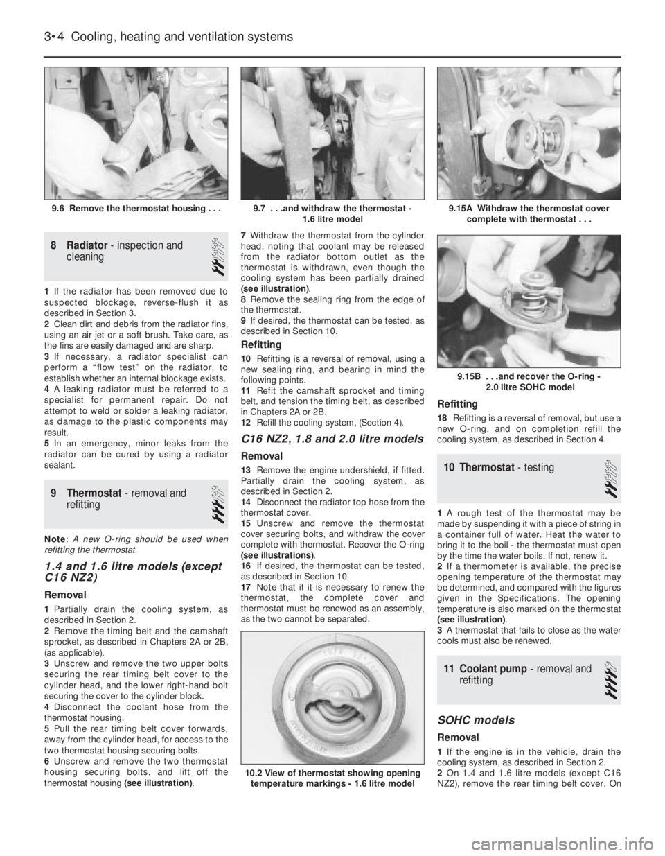
thermostat housing (see illustration).7Withdraw the thermostat from the cylinder
head, noting that coolant may be released
from the radiator bottom outlet as the
thermostat is withdrawn, even though the
cooling system has been partially drained
(see illustration).
8Remove the sealing ring from the edge of
the thermostat.
9If desired, the thermostat can be tested, as
described in Section 10.
Refitting
10Refitting is a reversal of removal, using a
new sealing ring, and bearing in mind the
following points.
11Refit the camshaft sprocket and timing
belt, and tension the timing belt, as described
in Chapters 2A or 2B.
12Refill the cooling system, (Section 4).
C16 NZ2, 1.8 and 2.0 litre models
Removal
13Remove the engine undershield, if fitted.
Partially drain the cooling system, as
described in Section 2.
14Disconnect the radiator top hose from the
thermostat cover.
15Unscrew and remove the thermostat
cover securing bolts, and withdraw the cover
complete with thermostat. Recover the O-ring
(see illustrations).
16If desired, the thermostat can be tested,
as described in Section 10.
17Note that if it is necessary to renew the
thermostat, the complete cover and
thermostat must be renewed as an assembly,
as the two cannot be separated.
Refitting
18Refitting is a reversal of removal, but use a
new O-ring, and on completion refill the
cooling system, as described in Section 4.
10Thermostat -testing
2
1A rough test of the thermostat may be
made by suspending it with a piece of string in
a container full of water. Heat the water to
bring it to the boil -the thermostat must open
by the time the water boils. If not, renew it.
2If a thermometer is available, the precise
opening temperature of the thermostat may
be determined, and compared with the figures
given in the Specifications. The opening
temperature is also marked on the thermostat
(see illustration).
3A thermostat that fails to close as the water
cools must also be renewed.
11Coolant pump -removal and
refitting
4
SOHC models
Removal
1If the engine is in the vehicle, drain the
cooling system, as described in Section 2.
2On 1.4 and 1.6 litre models (except C16
NZ2), remove the rear timing belt cover. On
3•4Cooling, heating and ventilation systems
9.6 Remove the thermostat housing . . .9.15A Withdraw the thermostat cover
complete with thermostat . . .
10.2 View of thermostat showing opening
temperature markings - 1.6 litre model
9.15B . . .and recover the O-ring -
2.0 litre SOHC model
9.7 . . .and withdraw the thermostat -
1.6 litre model
Page 236 of 525
C16 NZ2, 1.8 and 2.0 litre models, remove the
timing belt. Details are as described in
Chapter 2A.
3Remove timing belt tension roller from oil
pump, where applicable.
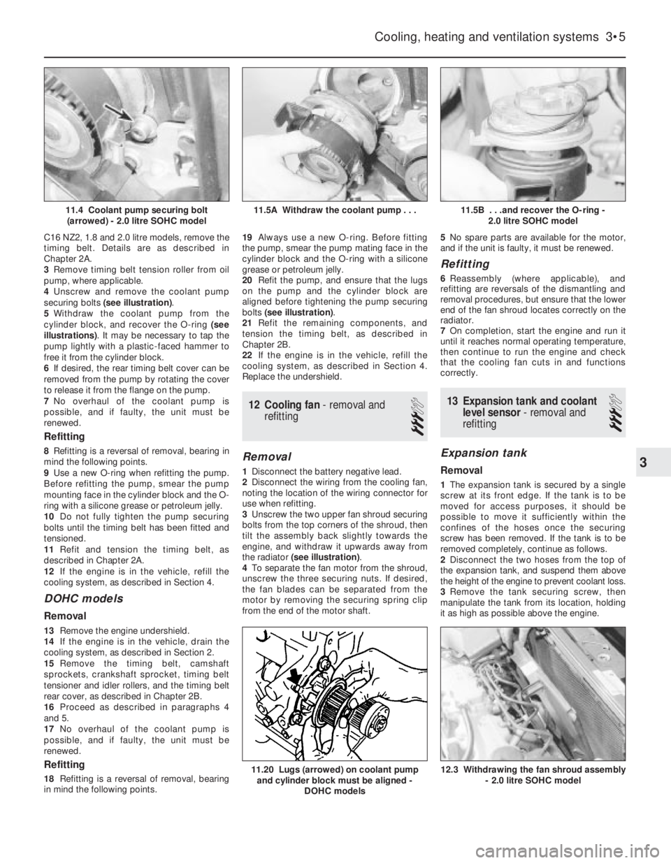
4Unscrew and remove the coolant pump
securing bolts (see illustration).
5Withdraw the coolant pump from the
cylinder block, and recover the O-ring (see
illustrations). It may be necessary to tap the
pump lightly with a plastic-faced hammer to
free it from the cylinder block.
6If desired, the rear timing belt cover can be
removed from the pump by rotating the cover
to release it from the flange on the pump.
7No overhaul of the coolant pump is
possible, and if faulty, the unit must be
renewed.
Refitting
8Refitting is a reversal of removal, bearing in
mind the following points.
9Use a new O-ring when refitting the pump.
Before refitting the pump, smear the pump
mounting face in the cylinder block and the O-
ring with a silicone grease or petroleum jelly.
10Do not fully tighten the pump securing
bolts until the timing belt has been fitted and
tensioned.
11Refit and tension the timing belt, as
described in Chapter 2A.
12If the engine is in the vehicle, refill the
cooling system, as described in Section 4.
DOHC models
Removal
13Remove the engine undershield.
14If the engine is in the vehicle, drain the
cooling system, as described in Section 2.
15Remove the timing belt, camshaft
sprockets, crankshaft sprocket, timing belt
tensioner and idler rollers, and the timing belt
rear cover, as described in Chapter 2B.
16Proceed as described in paragraphs 4
and 5.
17No overhaul of the coolant pump is
possible, and if faulty, the unit must be
renewed.
Refitting
18Refitting is a reversal of removal, bearing
in mind the following points.19Always use a new O-ring. Before fitting
the pump, smear the pump mating face in the
cylinder block and the O-ring with a silicone
grease or petroleum jelly.
20Refit the pump, and ensure that the lugs
on the pump and the cylinder block are
aligned before tightening the pump securing
bolts (see illustration).
21Refit the remaining components, and
tension the timing belt, as described in
Chapter 2B.
22If the engine is in the vehicle, refill the
cooling system, as described in Section 4.
Replace the undershield.
12Cooling fan - removal and
refitting
3
Removal
1Disconnect the battery negative lead.
2Disconnect the wiring from the cooling fan,
noting the location of the wiring connector for
use when refitting.
3Unscrew the two upper fan shroud securing
bolts from the top corners of the shroud, then
tilt the assembly back slightly towards the
engine, and withdraw it upwards away from
the radiator (see illustration).
4To separate the fan motor from the shroud,
unscrew the three securing nuts. If desired,
the fan blades can be separated from the
motor by removing the securing spring clip
from the end of the motor shaft.5No spare parts are available for the motor,
and if the unit is faulty, it must be renewed.
Refitting
6Reassembly (where applicable), and
refitting are reversals of the dismantling and
removal procedures, but ensure that the lower
end of the fan shroud locates correctly on the
radiator.
7On completion, start the engine and run it
until it reaches normal operating temperature,
then continue to run the engine and check
that the cooling fan cuts in and functions
correctly.
13Expansion tank and coolant
level sensor -removal and
refitting
3
Expansion tank
Removal
1The expansion tank is secured by a single
screw at its front edge. If the tank is to be
moved for access purposes, it should be
possible to move it sufficiently within the
confines of the hoses once the securing
screw has been removed. If the tank is to be
removed completely, continue as follows.
2Disconnect the two hoses from the top of
the expansion tank, and suspend them above
the height of the engine to prevent coolant loss.
3Remove the tank securing screw, then
manipulate the tank from its location, holding
it as high as possible above the engine.
Cooling, heating and ventilation systems 3•5
11.5B . . .and recover the O-ring -
2.0 litre SOHC model
12.3 Withdrawing the fan shroud assembly
- 2.0 litre SOHC model11.20 Lugs (arrowed) on coolant pump
and cylinder block must be aligned -
DOHC models
11.5A Withdraw the coolant pump . . .11.4 Coolant pump securing bolt
(arrowed) - 2.0 litre SOHC model
3
Page 242 of 525
Spare parts are available from many
sources, for example: Vauxhall dealers, other
garages and accessory shops, and motor
factors. Our advice regarding spare part
sources is as follows.
Officially appointed Vauxhall
dealers
This is the best source of parts that are
peculiar to your car and are otherwise not
generally available (e.g. complete cylinder
heads, transmission components, badges,
interior trim, etc.). It is also the only place at
which you should buy parts if your vehicle is
still under warranty -use of non-Vauxhall
components may invalidate the warranty. To
be sure of obtaining the correct parts it willalways be necessary to give the storeman
your car’s vehicle identification number, and if
possible, to take the “old” parts along for
positive identification. Remember that many
parts are available on a factory exchange
scheme -any parts returned should always be
clean! It obviously makes good sense to go
straight to the specialists on your car for this
type of part for they are best equipped to
supply you.
Other garages and accessory
shops
These are often very good places to buy
materials and components needed for the
maintenance of your car (e.g. oil filters, spark
plugs, bulbs, drivebelts, oils and greases,touch-up paint, filler paste, etc.). They also
sell general accessories, usually have
convenient opening hours, charge lower
prices and can often be found not far from
home.
Motor factors
Good factors will stock all the more
important components that wear out
relatively quickly (e.g. clutch components,
pistons, valves, exhaust systems, brake
cylinders/pipes/hoses/seals/shoes and pads,
etc.). Motor factors will often provide new or
reconditioned components on a part
exchange basis -this can save considerable
amount of money.
Modifications are a continuing and
unpublished process in vehicle manufacture,
quite apart from major model changes. Spare
parts manuals and lists are compiled upon a
numerical basis, the individual vehicle
numbers being essential to correct identifi-
cation of the component required.
When ordering spare parts, always give as
much information as possible. Quote the car
model, year of manufacture and vehicle iden-
tification and/or engine numbers as
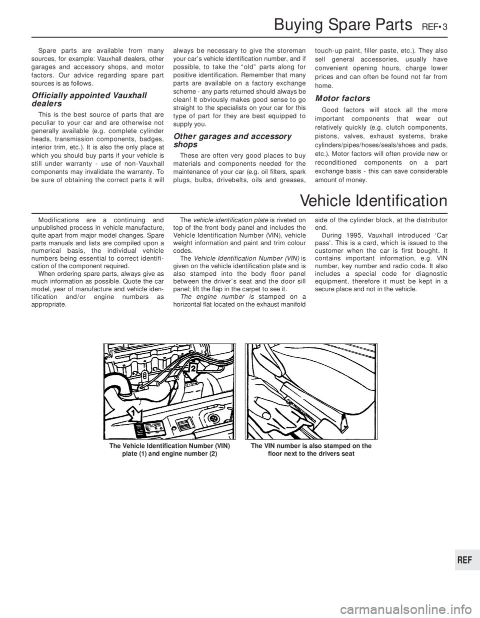
appropriate.The vehicle identification plate is riveted on
top of the front body panel and includes the
Vehicle Identification Number (VIN), vehicle
weight information and paint and trim colour
codes.
The Vehicle Identification Number (VIN) is
given on the vehicle identification plate and is
also stamped into the body floor panel
between the driver’s seat and the door sill
panel; lift the flap in the carpet to see it.
The engine number is stamped on a
horizontal flat located on the exhaust manifoldside of the cylinder block, at the distributor
end.
During 1995, Vauxhall introduced ‘Car
pass’. This is a card, which is issued to the
customer when the car is first bought. It
contains important information, e.g. VIN
number, key number and radio code. It also
includes a special code for diagnostic
equipment, therefore it must be kept in a
secure place and not in the vehicle.
Buying Spare Parts REF•3
The VIN number is also stamped on the
floor next to the drivers seatThe Vehicle Identification Number (VIN)
plate (1) and engine number (2)
REF
Vehicle Identification