1988 OPEL VECTRA ignition
[x] Cancel search: ignitionPage 92 of 525
5If the engine turns over at normal speed but
will not start, check the HT circuit by
connecting a timing light and turning the
engine over on the starter motor. If the light
flashes, voltage is reaching the spark plugs,
so these should be checked first. If the light
does not flash, check the HT leads
themselves followed by the distributor cap,
carbon brush and rotor arm.
6If there is a spark, check the fuel system for
faults as far as possible (Chapters 4A or 4B).
7If there is still no spark, check the voltage at
the ignition coil “+” or “15” terminal; it should
be the same as the battery voltage (i.e., at
least 11.7 volts). If the voltage at the coil is
more than 1 volt less than that at the battery,
check the connections back through the
ignition switch to the battery and its earth until
the fault is found. Note, however, that the
ECU controls the coil’s feed; do not attempt
to “test” the ECU with anything other than the
correct test equipment, which will be available
only to a Vauxhall dealer. If any of the wires
are to be checked which lead to the ECU,
always first unplug the relevant connector
from the ECU so that there is no risk of the
ECU being damaged by the application of
incorrect voltages from test equipment.
8If the feed to the ignition coil is sound,
check the coil’s primary and secondary
windings (refer to Section 16). Renew the coil
if faulty, but check the condition of the LT
connections themselves before doing so, to
ensure that the fault is not due to dirty or
poorly fastened connectors.
9If the ignition coil is in good condition, the
fault may be within the amplifier module or the
distributor on the C16 NZ and C16 NZ2
engines, or the amplifier or the crankshaft
speed/position sensor on the C18 NZ engine.
A quick check of these components can be
made by connecting a low-wattage bulb
across the ignition coil’s (disconnected) LT
terminals. If the bulb flickers or flashes when
the engine is turned over, the amplifier and
distributor (C16 NZ and C16 NZ2 engines), or
amplifier and crankshaft speed/position
sensor (C18 NZ engine), are sound.
10If this is the case, the entire LT circuit is in
good condition; the fault, if it lies in the
ignition system, must be in the HT circuit
components. These should be checked
carefully, as outlined above.
11If the indicator or bulb does not flash, the
fault is in either the amplifier or the distributor
(C16 NZ and C16 NZ2 engines), or the
amplifier or crankshaft speed/position sensor
(C18 NZ engine). Owners should note,
however, that by far the commonest cause of
“failure” of either of these is a poor
connection, either between the components
themselves or in the LT circuit wiring
connections. If such a fault is suspected, the
vehicle must be taken to a suitably equipped
Vauxhall dealer for testing; no information is
available to eliminate these components by
other means.12An irregular misfire suggests either a
loose connection or intermittent fault on the
primary circuit, or a HT fault on the coil side of
the rotor arm.
13With the ignition switched off, check
carefully through the system ensuring that all
connections are clean and securely fastened.
If the equipment is available, check the LT
circuit as described in paragraphs 7 to 11
above.
14Check that the HT coil, the distributor cap
and the HT leads are clean and dry. Check the
leads and the spark plugs (by substitution, if
necessary), then check the distributor cap,
carbon brush and rotor arm.
15Regular misfiring is almost certainly due to
a fault in the distributor cap, HT leads or spark
plugs. Use a timing light (paragraph 5, above)
to check whether HT voltage is present at all
leads.
16If HT voltage is not present on any
particular lead, the fault will be in that lead or
in the distributor cap. If HT is present on all
leads, the fault will be in the spark plugs;
check and renew them if there is any doubt
about their condition.
17If no HT voltage is present, check the
ignition coil; its secondary windings may be
breaking down under load.
18If all components have been checked for
signs of obvious faults but the system is still
thought to be faulty, take the vehicle to a
Vauxhall dealer for testing on special
equipment.
5Battery - testing and charging
2
Note: Refer to Section 3 before proceeding.
Testing
1Topping-up and testing of the electrolyte in
each cell is not possible. The condition of the
battery can therefore only be tested by
observing the battery condition indicator.
2The battery condition indicator is fitted in
the top of the battery casing, and indicates
the condition of the battery from its colour. If
the indicator shows green, then the battery is
in a good state of charge. If the indicator turns
darker, eventually to black, then the battery
requires charging, as described later in this
Section. If the indicator shows clear/yellow,
then the electrolyte level in the battery is too
low to allow further use, and the battery
should be renewed.
Charging
3Do not attempt to charge, load or jump start
a battery when the indicator shows
clear/yellow. If the battery is to be charged,
remove it from the vehicle and charge it as
follows.
4The maintenance-free type battery takes
considerably longer to fully recharge than the
standard type, the time taken being
dependent on the extent of discharge.5A constant-voltage type charger is required,
to be set, when connected, to 13.9 to 14.9
volts with a charger current below 25 amps.
6If the battery is to be charged from a fully
discharged state (less than 12.2 volts output),
have it recharged by a Vauxhall dealer or
battery specialist, as the charge rate will be
high and constant supervision during charging
is necessary.
6Battery - removal and refitting
2
Note: Refer to Section 3 before proceeding.
Removal
1The battery is located at the left-hand front
corner of the engine compartment.
2Disconnect the lead(s) at the negative
(earth) terminal by unscrewing the retaining
nut and removing the terminal clamp.
3Disconnect the positive terminal lead(s) in
the same way.
4Unscrew the clamp bolt sufficiently to
enable the battery to be lifted from its
location. Keep the battery in an upright
position, to avoid spilling electrolyte on the
bodywork.
Refitting
5Refitting is a reversal of removal, but smear
petroleum jelly on the terminals when
reconnecting the leads, and always connect
the positive lead first and the negative lead
last.
7Alternator - description
1A Delco-Remy or Bosch alternator may be
fitted, depending on model and engine
capacity. The maximum output of the
alternator varies accordingly.
2The alternator is belt-driven from the
crankshaft pulley. Cooling is provided by a
fan, mounted outside the casing on the end of
the rotor shaft. An integral voltage regulator is
incorporated, to control the output voltage.
3The alternator provides a charge to the
battery even at very low engine speed, and
consists of a coil-wound stator in which a
rotor rotates. The rotor shaft is supported in
ball-bearings, and slip rings are used to
conduct current to and from the field coils
through the carbon brushes.
4The alternator generates ac (alternating
current), which is rectified by an internal diode
circuit to dc (direct current) for supply to the
battery.
5Later models are fitted with a Delco-Remy,
‘compact’ series alternators (see illustration).
They use a ribbed V-belt type drivebelt with
automatic tensioner. They are rigidly mounted
to the engine.
Engine electrical systems 5•5
5
Page 96 of 525
2When the starter switch is operated, current
flows from the battery to the solenoid that is
mounted on the starter body. The plunger in
the solenoid moves inwards, so causing a
centrally pivoted lever to push the drive pinion
into mesh with the starter ring gear. When the
solenoid plunger reaches the end of its travel,
it closes an internal contact and full starting
current flows to the starter field coils. The
armature is then able to rotate the crankshaft,
so starting the engine.
3A special freewheel clutch is fitted to the
starter driven pinion, so that when the engine
fires and starts to operate on its own it does
not drive the starter motor.
4When the starter switch is released, the
solenoid is de-energised, and a spring moves
the plunger back to its rest position. This
operates the pivoted lever to the withdraw the
drive pinion from engagement with the starter
ring.
13Starter motor - testing
3
Note: Refer to Section 3 before proceeding
Testing
1If the starter motor fails to turn the engine
when the switch is operated, and engine
seizure is not the problem, there are several
other possible reasons:
a)The battery is faulty
b)The electrical connections between the
switch, solenoid battery and starter motor
are somewhere failing to pass the
necessary current from the battery
through the starter to earth
c)The solenoid switch is faulty
d)The starter motor is mechanically or
electrically defective
e)The starter motor pinion and/or flywheel
ring gear is badly worn, and in need of
replacement
2To check the battery, switch on the
headlamps. If they dim after a few seconds,
then the battery is in a discharged state. If the
lamps glow brightly, operate the starter switch
and see what happens to the lamps. If theydim, then power is reaching the motor, but
failing to turn it. If the starter turns slowly, go
on to the next check.
3If, when the starter switch is operated, the
lamps stay bright, then insufficient power is
reaching the motor. Disconnect the battery
and the starter/solenoid power connections,
and the engine earth strap, then thoroughly
clean them and refit them. Smear petroleum
jelly around the battery connections to
prevent corrosion. Corroded connections are
the most frequent cause of electrical system
malfunctions.
4If the preceding checks and cleaning tasks
have been carried out without success, a
clicking noise will probably have been heard
each time the starter switch was operated.
This indicates that the solenoid switch was
operating, but it does not necessarily follow
that the main contacts were closing properly
(if no clicking has been heard from the
solenoid, it is certainly defective). The
solenoid can be checked by connecting a
voltmeter across the main cable connection
on the solenoid and earth. When the switch is
operated, these should be a reading on the
voltmeter. If there is no reading, the solenoid
unit is faulty, and should be renewed.
5If the starter motor operates, but does not
turn the engine, then it is likely that the starter
pinion and/or flywheel ring gear are badly
worn. If this is the case, the starter motor will
normally be noisy in operation.
6Finally, if it is established that the solenoid
is not faulty, and 12 volts are reaching the
starter, then the motor itself is faulty, and
should be removed for inspection.
14Starter motor - removal and
refitting
3
Note: Refer to Section 3 before proceeding
Removal
1Disconnect the battery negative lead.
2Apply the handbrake, then jack up the front
of the vehicle, and support securely on axle
stands (see “Jacking and Vehicle Support”)
positioned under the body side members.3On DOHC models, remove the engine
undershield, as described in Chapter 11.
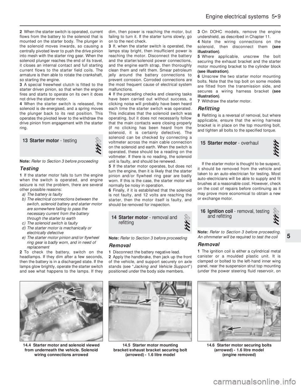
4Note the wiring connections on the
solenoid, then disconnect them (see
illustration).
5Where applicable, unscrew the bolt
securing the exhaust bracket and the starter
motor mounting bracket to the cylinder block
(see illustration).
6Unscrew the two starter motor mounting
bolts. Note that the top bolt on some models
are fitted from the transmission side, and
secures a wiring harness bracket (see
illustration).
7Withdraw the starter motor.
Refitting
8Refitting is a reversal of removal, but where
applicable, ensure that the wiring harness
bracket is in place on the top mounting bolt,
and tighten all bolts to the specified torque.
15Starter motor - overhaul
5
If the starter motor is thought to be suspect,
it should be removed from the vehicle and
taken to an auto-electrician for testing. Most
auto-electricians will be able to supply and fit
brushes at a reasonable cost. However, check
on the cost of repairs before continuing as it
may prove more economical to obtain a new
or exchange motor.
16Ignition coil - removal, testing
and refitting
3
Note: Refer to Section 3 before proceeding.
An ohmmeter will be required to test the coil
Removal
1The ignition coil is either a cylindrical metal
canister or a moulded plastic unit. It is
clamped or bolted to the left-hand inner wing
panel, near the suspension strut top mounting
(under the power steering fluid reservoir, on
Engine electrical systems 5•9
14.6 Starter motor securing bolts
(arrowed) - 1.6 litre model
(engine removed)14.5 Starter motor mounting
bracket/exhaust bracket securing bolt
(arrowed) - 1.6 litre model14.4 Starter motor and solenoid viewed
from underneath the vehicle. Solenoid
wiring connections arrowed
5
Page 97 of 525
models so equipped). On 14 NV, 16 SV and
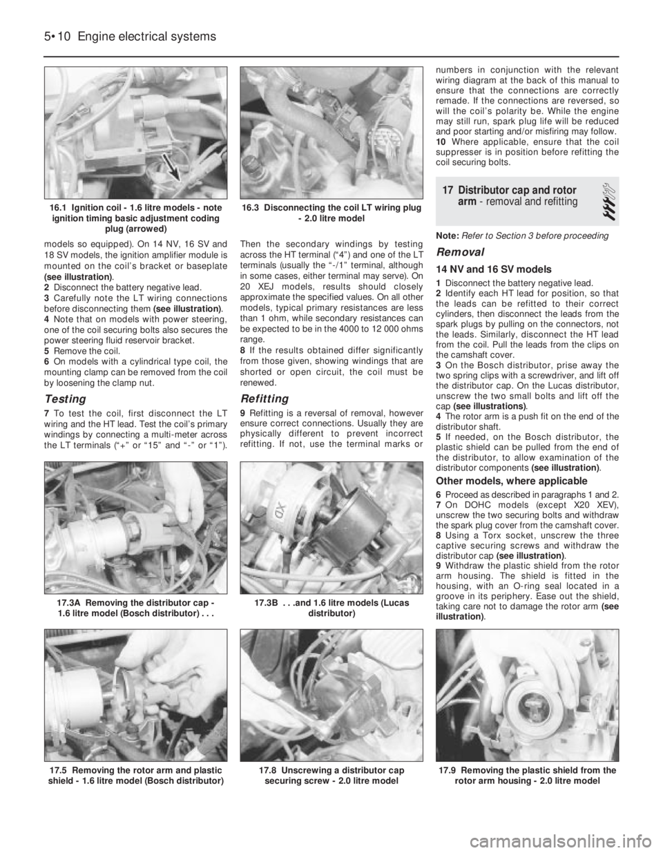
18 SV models, the ignition amplifier module is
mounted on the coil’s bracket or baseplate
(see illustration).
2Disconnect the battery negative lead.
3Carefully note the LT wiring connections
before disconnecting them (see illustration).
4Note that on models with power steering,
one of the coil securing bolts also secures the
power steering fluid reservoir bracket.
5Remove the coil.
6On models with a cylindrical type coil, the
mounting clamp can be removed from the coil
by loosening the clamp nut.
Testing
7To test the coil, first disconnect the LT
wiring and the HT lead. Test the coil’s primary
windings by connecting a multi-meter across
the LT terminals (“+” or “15” and “-” or “1”).Then the secondary windings by testing
across the HT terminal (“4”) and one of the LT
terminals (usually the “-/1” terminal, although
in some cases, either terminal may serve). On
20 XEJ models, results should closely
approximate the specified values. On all other
models, typical primary resistances are less
than 1 ohm, while secondary resistances can
be expected to be in the 4000 to 12 000 ohms
range.
8If the results obtained differ significantly
from those given, showing windings that are
shorted or open circuit, the coil must be
renewed.
Refitting
9Refitting is a reversal of removal, however
ensure correct connections. Usually they are
physically different to prevent incorrect
refitting. If not, use the terminal marks ornumbers in conjunction with the relevant
wiring diagram at the back of this manual to
ensure that the connections are correctly
remade. If the connections are reversed, so
will the coil’s polarity be. While the engine
may still run, spark plug life will be reduced
and poor starting and/or misfiring may follow.
10Where applicable, ensure that the coil
suppresser is in position before refitting the
coil securing bolts.
17Distributor cap and rotor
arm -removal and refitting
3
Note: Refer to Section 3 before proceeding
Removal
14 NV and 16 SV models
1Disconnect the battery negative lead.
2Identify each HT lead for position, so that
the leads can be refitted to their correct
cylinders, then disconnect the leads from the
spark plugs by pulling on the connectors, not
the leads. Similarly, disconnect the HT lead
from the coil. Pull the leads from the clips on
the camshaft cover.
3On the Bosch distributor, prise away the
two spring clips with a screwdriver, and lift off
the distributor cap. On the Lucas distributor,
unscrew the two small bolts and lift off the
cap (see illustrations).
4The rotor arm is a push fit on the end of the
distributor shaft.
5If needed, on the Bosch distributor, the
plastic shield can be pulled from the end of
the distributor, to allow examination of the
distributor components (see illustration).
Other models, where applicable
6Proceed as described in paragraphs 1 and 2.
7On DOHC models (except X20 XEV),
unscrew the two securing bolts and withdraw
the spark plug cover from the camshaft cover.
8Using a Torx socket, unscrew the three
captive securing screws and withdraw the
distributor cap (see illustration).
9Withdraw the plastic shield from the rotor
arm housing. The shield is fitted in the
housing, with an O-ring seal located in a
groove in its periphery. Ease out the shield,
taking care not to damage the rotor arm (see
illustration).
5•10Engine electrical systems
16.1 Ignition coil - 1.6 litre models - note
ignition timing basic adjustment coding
plug (arrowed)
17.3A Removing the distributor cap -
1.6 litre model (Bosch distributor) . . .
17.9 Removing the plastic shield from the
rotor arm housing - 2.0 litre model17.8 Unscrewing a distributor cap
securing screw - 2.0 litre model17.5 Removing the rotor arm and plastic
shield - 1.6 litre model (Bosch distributor)
17.3B . . .and 1.6 litre models (Lucas
distributor)
16.3 Disconnecting the coil LT wiring plug
- 2.0 litre model
Page 98 of 525
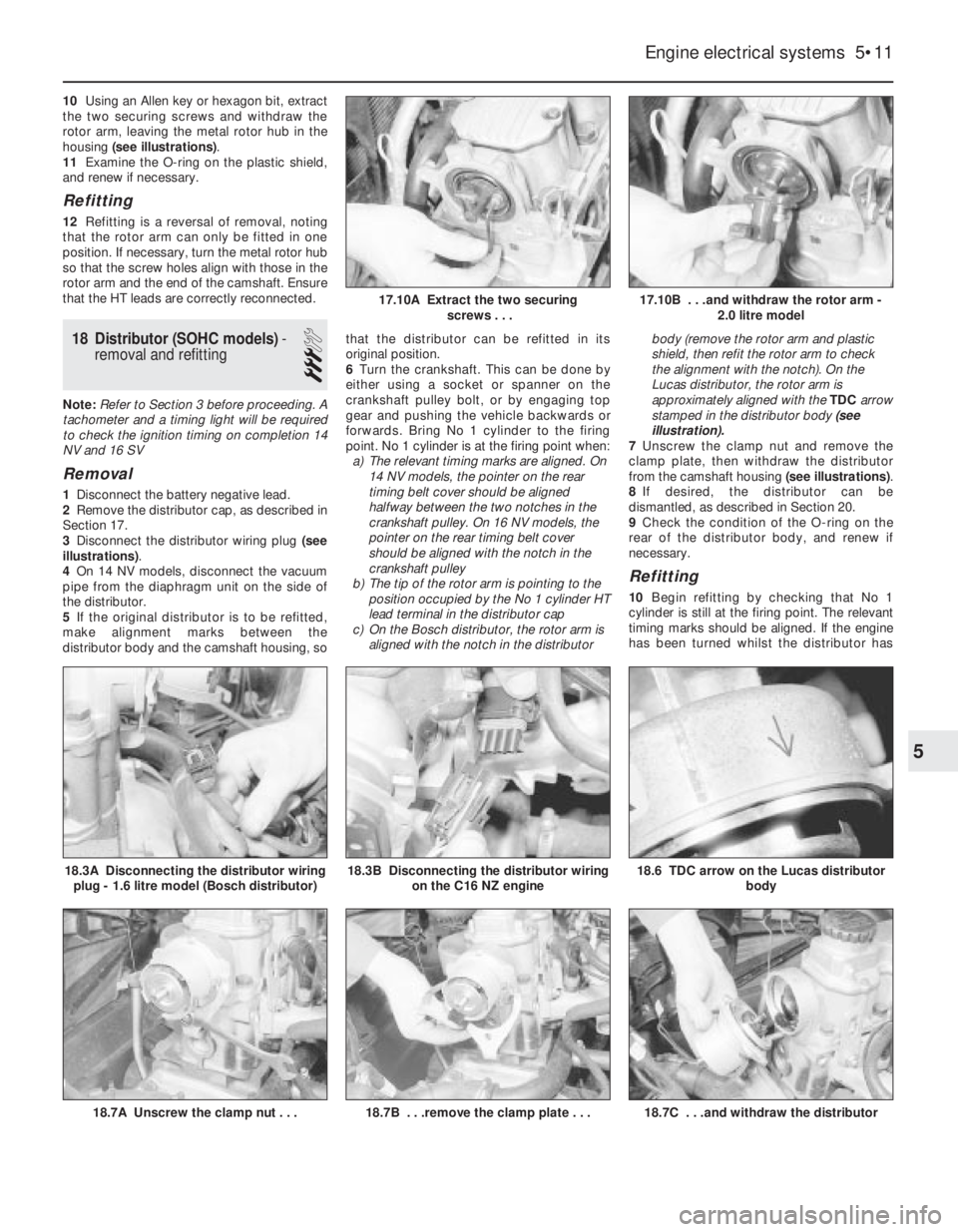
10Using an Allen key or hexagon bit, extract
the two securing screws and withdraw the
rotor arm, leaving the metal rotor hub in the
housing (see illustrations).
11Examine the O-ring on the plastic shield,
and renew if necessary.
Refitting
12Refitting is a reversal of removal, noting
that the rotor arm can only be fitted in one
position. If necessary, turn the metal rotor hub
so that the screw holes align with those in the
rotor arm and the end of the camshaft. Ensure
that the HT leads are correctly reconnected.
18Distributor (SOHC models) -
removal and refitting
3
Note: Refer to Section 3 before proceeding. A
tachometer and a timing light will be required
to check the ignition timing on completion 14
NV and 16 SV
Removal
1Disconnect the battery negative lead.
2Remove the distributor cap, as described in
Section 17.
3Disconnect the distributor wiring plug (see
illustrations).
4On 14 NV models, disconnect the vacuum
pipe from the diaphragm unit on the side of
the distributor.
5If the original distributor is to be refitted,
make alignment marks between the
distributor body and the camshaft housing, sothat the distributor can be refitted in its
original position.
6Turn the crankshaft. This can be done by
either using a socket or spanner on the
crankshaft pulley bolt, or by engaging top
gear and pushing the vehicle backwards or
forwards. Bring No 1 cylinder to the firing
point. No 1 cylinder is at the firing point when:
a)The relevant timing marks are aligned. On
14 NV models, the pointer on the rear
timing belt cover should be aligned
halfway between the two notches in the
crankshaft pulley. On 16 NV models, the
pointer on the rear timing belt cover
should be aligned with the notch in the
crankshaft pulley
b)The tip of the rotor arm is pointing to the
position occupied by the No 1 cylinder HT
lead terminal in the distributor cap
c)On the Bosch distributor, the rotor arm is
aligned with the notch in the distributorbody (remove the rotor arm and plastic
shield, then refit the rotor arm to check
the alignment with the notch). On the
Lucas distributor, the rotor arm is
approximately aligned with the TDC arrow
stamped in the distributor body (see
illustration).
7Unscrew the clamp nut and remove the
clamp plate, then withdraw the distributor
from the camshaft housing (see illustrations).
8If desired, the distributor can be
dismantled, as described in Section 20.
9Check the condition of the O-ring on the
rear of the distributor body, and renew if
necessary.
Refitting
10Begin refitting by checking that No 1
cylinder is still at the firing point. The relevant
timing marks should be aligned. If the engine
has been turned whilst the distributor has
Engine electrical systems 5•11
18.6 TDC arrow on the Lucas distributor
body
18.7C . . .and withdraw the distributor18.7B . . .remove the clamp plate . . .18.7A Unscrew the clamp nut . . .
18.3B Disconnecting the distributor wiring
on the C16 NZ engine18.3A Disconnecting the distributor wiring
plug - 1.6 litre model (Bosch distributor)
17.10B . . .and withdraw the rotor arm -
2.0 litre model17.10A Extract the two securing
screws . . .
5
Page 99 of 525
been removed, check that No 1 cylinder is on
its firing stroke by removing No 1 cylinder
spark plug and placing a finger over the plug
hole. Turn the crankshaft until compression
can be felt, which indicates that No 1 piston is
rising on its compression stroke. Continue
turning the crankshaft until the relevant timing
marks are in alignment.
11Turn the rotor arm to the position noted in
paragraph 6c, and hold the rotor arm in this
position as the distributor is fitted. Note that
the distributor driveshaft will only engage with
the camshaft in one position. If the original
distributor is being refitted, align the marks
made on the distributor body and camshaft
housing before removal.
12Refit the clamp plate and nut, but do not
fully tighten the nut at this stage.
13On the Bosch distributor, remove the rotor
arm, then refit the plastic shield and the rotor
arm.
14On 14 NV models, reconnect the vacuum
pipe to the diaphragm unit.
15Reconnect the distributor wiring plug.
16Refit the distributor cap as described in
Section 17.
17Reconnect the battery negative lead.
18Check and if necessary adjust the ignition
timing, as described in Section 21.
19Distributor (DOHC models),
where applicable - removal
and refitting
3
Removal
1Disconnect the battery negative lead.
2Remove the distributor cap, as described in
Section 17.
3Disconnect the distributor wiring plug.
4Unscrew the two securing bolts, and
remove the distributor from the cylinder head.
5Examine the O-ring on the rear of the
distributor, and renew if necessary.
Refitting
6Refitting is a reversal of removal. However,
note that the distributor should be fitted so
that the wiring plug is positioned on the upper
left-hand side of the distributor body, when
viewed from the distributor cap end.
20Distributor - dismantling,
inspection and reassembly
3
Note: Before contemplating dismantling of a
distributor, check the cost and availability of
replacement parts. It may prove more
economical to renew the complete distributor
assembly
14 NV models
Dismantling
1With the distributor removed as described
in Section 18, continue as follows.
2Pull off the rotor arm, and remove the
plastic shield.
3The top bearing plate can be removed after
unscrewing the two securing screws, however
(other than the vacuum diaphragm unit), no
spares are available for the distributor and no
adjustments are required.
4If desired, the vacuum diaphragm unit can
be removed by extracting the two securing
screws and unhooking the operating arm from
the distributor baseplate. Note that the
screws are of differing lengths, the longer
screw also secures one of the distributor cap
clips.
Inspection
5The vacuum unit can be tested by applying
suction to the vacuum port, and checking that
the operating rod moves into the unit as
suction is applied. Remove the suction, and
check that the operating rod returns to its
original position. If the operating rod does not
move as described, renew the vacuum unit.
6Check the distributor cap for corrosion of
the segments, and for signs of tracking,
indicated by a thin black line between the
segments. Make sure that the carbon brush in
the centre of the cap moves freely and stands
proud of the surface of the cap. Renew the
cap if necessary.
7If the metal portion of the rotor arm is badly
burnt or loose, renew it. If slightly burnt or
corroded; it may be cleaned with a fine file.
8Examine the seal ring at the rear of the
distributor body, and renew if necessary.
Reassembly
9Reassembly is a reversal of dismantling,
ensuring that the vacuum unit operating arm
is correctly engaged with the peg on the
baseplate, several attempts may be required
to reconnect it.
10Refit the distributor as described in
Section 18, and then check and if necessary
adjust the ignition timing, as described in
Section 21.
16 SV models
Dismantling
11With the distributor removed as described
in Section 18, pull off the rotor arm and, on
the Bosch distributor, remove the plastic
shield.
12Using a pin punch, carefully drive out the
roll pin securing the plastic drive collar to the
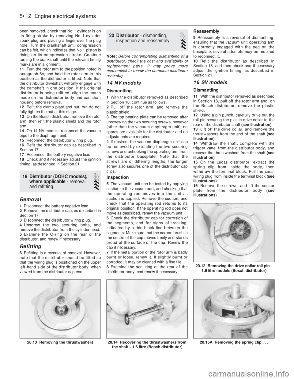
rear of the distributor shaft (see illustration).
13Lift off the drive collar, and remove the
thrustwashers from the end of the shaft (see
illustration).
14Withdraw the shaft, complete with the
trigger vane, from the distributor body, and
recover the thrustwashers from the shaft (see
illustration).
15On the Lucas distributor, extract the
spring clip from inside the body, then
withdraw the terminal block. Pull the small
wiring plug from inside the terminal block (see
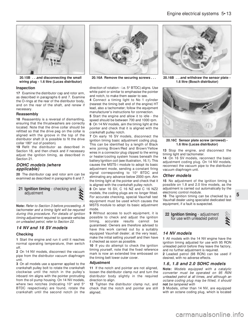
illustrations).
16Remove the screws, and lift the sensor
plate from the distributor body (see
illustrations).
5•12Engine electrical systems
20.15A Removing the spring clip . . .20.14 Recovering the thrustwashers from
the shaft - 1.6 litre (Bosch distributor)20.13 Removing the thrustwashers
20.12 Removing the drive collar roll pin -
1.6 litre models (Bosch distributor)
Page 100 of 525
Inspection
17Examine the distributor cap and rotor arm,
as described in paragraphs 6 and 7. Examine
the O-rings at the rear of the distributor body,
and on the rear of the shaft, and renew if
necessary.
Reassembly
18Reassembly is a reversal of dismantling,
ensuring that the thrustwashers are correctly
located. Note that the drive collar should be
refitted so that the drive peg on the collar is
aligned with the groove in the top of the
distributor shaft (it is possible to fit the drive
collar 180°out of position).
19Refit the distributor as described in
Section 18, and then check and if necessary
adjust the ignition timing, as described in
Section 21.
DOHC models (where
applicable)
20The distributor cap and rotor arm can be
examined as described in paragraphs 6 and 7.
21Ignition timing -checking and
adjustment
4
Note: Refer to Section 3 before proceeding. A
tachometer and a timing light will be required
during this procedure. For details of ignition
timing adjustment required to operate vehicles
on unleaded petrol, refer to Section 22.
14 NV and 16 SV models
Checking
1Start the engine and run it until it reaches
normal operating temperature, then switch
off.
2On 14 NV models, disconnect the vacuum
pipe from the distributor vacuum diaphragm
unit.
3On all models use a spanner applied to the
crankshaft pulley bolt to rotate the crankshaft
clockwise until the notch in the pulley’s
inboard rim aligns with the pointer protruding
from the oil pump housing. On 14 NV models,
where two notches (indicating 10°and 5°
BTDC respectively) are found, rotate the
crankshaft until the second notch (in thedirection of rotation -i.e. 5°BTDC) aligns. Use
white paint or similar to emphasise the pointer
and notch, to make them easier to see.
4Connect a timing light to No 1 cylinder
(nearest the timing belt end of the engine) HT
lead, also a tachometer; follow the equipment
manufacturer’s instructions for connection.
5Start the engine and allow it to idle -the
speed should be between 700 and 1000 rpm.
6On 14 NV models, aim the timing light at the
pointer and check that it is aligned with the
crankshaft pulley notch.
7On early 16 SV models, disconnect the
ignition timing basic adjustment coding plug.
This can be identified by a length of Black
wire joining Brown/Red and Brown/Yellow
wires in a connector plug clipped to the wiring
or heater/cooling system hoses beneath the
battery/ignition coil (see illustration, 16.1). This
causes the MSTS-i module to adopt its basic
adjustment mode, sending a constant firing
signal corresponding to 10°BTDC and
eliminating any advance below 2000 rpm. Aim
the timing light at the pointer and check that it
is aligned with the crankshaft pulley notch.
8On later 16 SV, C 16 NZ and C 16 NZ2
models, the coding plugs are no longer fitted.
For accurate checking, special Vauxhall test
equipment must be used which causes the
MSTS module to adopt its basic adjustment
mode.
9Without access to such equipment, it is
possible to check and adjust the ignition
timing, accurate results cannot be
guaranteed. Owners are therefore advised to
have this work carried out by a suitably
equipped Vauxhall dealer; at the very least,
make the initial setting yourself and then have
it checked as soon as possible.
10If you do attempt to check the ignition
timing yourself, note that the fixed reference
mark is now an extended line embossed on
the timing belt lower outer cover.
Adjustment
11If the notch and pointer are not aligned,
loosen the distributor clamp nut and turn the
distributor body slightly in the required
direction to align.
12Tighten the distributor clamp nut, and
check that the notch and pointer are still
aligned. 13Stop the engine, and disconnect the
timing light and tachometer.
14On 16 SV models, reconnect the basic
adjustment coding plug. On 14 NV models,
reconnect the vacuum pipe to the distributor
vacuum diaphragm unit.
Other models
15No adjustment of the ignition timing is
possible on 1.8 and 2.0 litre models, as the
adjustment is carried out automatically by the
electronic control module.
16The ignition timing can be checked by a
Vauxhall dealer using specialist dedicated test
equipment, if a fault is suspected.
22Ignition timing -adjustment
for use with unleaded petrol
3
14 NV models
1All models with the 14 NV engine have the
ignition timing adjusted for use with 95 RON
unleaded petrol before they leave the factory,
and no further adjustment is required.
2Leaded petrol (98 RON) can be used if
desired, with no adverse effects.
1.6, 1.8 and 2.0 SOHC models
Note: Models equipped with a catalytic
converter must be operated on 95 R0N
unleaded petrol at all times, and although an
octane coding plug may be fitted, it should
not be tampered with
3Models, other than 14 NV, are equipped
with an octane coding plug, which is located
Engine electrical systems 5•13
20.16B . . .and withdraw the sensor plate -
1.6 litre (Bosch distributor)
20.16C Sensor plate screw (arrowed) -
1.6 litre (Lucas distributor)
20.16A Remove the securing screws . . .20.15B . . .and disconnecting the small
wiring plug - 1.6 litre (Lucas distributor)
5
Page 101 of 525
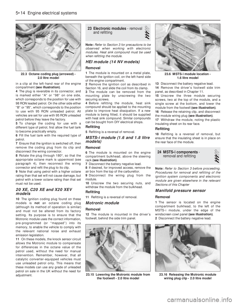
in a clip at the left-hand rear of the engine
compartment (see illustration).
4The plug is reversible in its connector, and
is marked either “A” or “98” on one side,
which corresponds to the position for use with
98 RON leaded petrol. On the other side either
“B” or “95”, which corresponds to the position
to use with 95 RON unleaded petrol. All
vehicles are set for use with 95 RON unleaded
petrol before they leave the factory.
5To change the coding for use with a
different type of petrol, first allow the fuel tank
to become practically empty.
6Fill the fuel tank with the required type of
petrol.
7Ensure that the ignition is switched off, then
remove the coding plug from its clip and
disconnect the wiring connector.
8Rotate the plug through 180°, so that the
appropriate octane mark is uppermost (see
paragraph 4), then reconnect the wiring
connector and refit the plug to its clip.
9Note that using petrol with a higher octane
rating than that set will not cause damage, but
petrol with a lower octane rating than that set
must not be used.
20 XE, C20 XE and X20 XEV
models
10The ignition coding plug found on these
models is not an octane coding plug
(although its method of operation is similar)
and must not be altered from its factory
setting. Its purpose is to ensure that the
Motronic module uses the correct information,
pre-programmed (or “mapped”) into its
memory, to enable the vehicle to comply with
the relevant national noise and exhaust
emission legislation.
11On these models, the knock sensor circuit
allows the Motronic module to compensate
for differences in the octane value of the
petrol used, without the need for manual
intervention. Remember, however, that all
catalytic converter-equipped vehicles must
use unleaded petrol only. This means that
these models can use any grade of unleaded
petrol on sale in the UK without the need for
adjustment.
23Electronic modules - removal
and refitting
3
Note: Refer to Section 3 for precautions to be
observed when working with electronic
modules. Heat sink compound must be used
when refitting the module.
HEI module (14 NV models)
Removal
1The module is mounted on a metal plate,
beneath the ignition coil, on the left-hand side
of the engine compartment.
2Remove the ignition coil as described in
Section 16, and slide the coil from its clamp.
3The module can be removed from the
mounting plate by unscrewing the two
securing screws.
4Before refitting the module, heat sink
compound should be applied to the mounting
plate to improve heat dissipation. If a new
module is being fitted, it should be supplied
with heat sink compound. Similar compounds
can be bought from DIY electrical shops.
Refitting
5Refitting is a reversal of removal.
MSTS-i module (1.6 and 1.8 litre
models)
Removal
6The module is mounted on the engine
compartment bulkhead, above the steering
rack (see illustration).
7Disconnect the battery negative lead.
8If desired, for improved access, remove the
air box from the top of the carburettor.
9Disconnect the wiring plug from the
module.
10Unscrew the two securing nuts, and
withdraw the module from the bulkhead.
Refitting
11Refitting is a reversal of removal.
Motronic module
Removal
12The module is mounted in the driver’s
footwell, behind the side trim panel.13Disconnect the battery negative lead.
14Remove the driver’s footwell side trim
panel, as described in Chapter 11.
15Unscrew the three module securing
screws, two at the top of the module, and a
single screw at the bottom, and lower the
module from the footwell (see illustration).
16Release the retaining clip, and disconnect
the module wiring plug (see illustration).
17Withdraw the module, noting the plastic
insulating sheet on its rear face.
Refitting
18Refitting is a reversal of removal, but
ensure that the insulating sheet is in place on
the rear face of the module.
24MSTS-i components -
removal and refitting
3
Note: Refer to Section 3 before proceeding.
Procedures for removal and refitting of the
ignition system components and electronic
module are given elsewhere in the relevant
Sections of this Chapter
Manifold pressure sensor
Removal
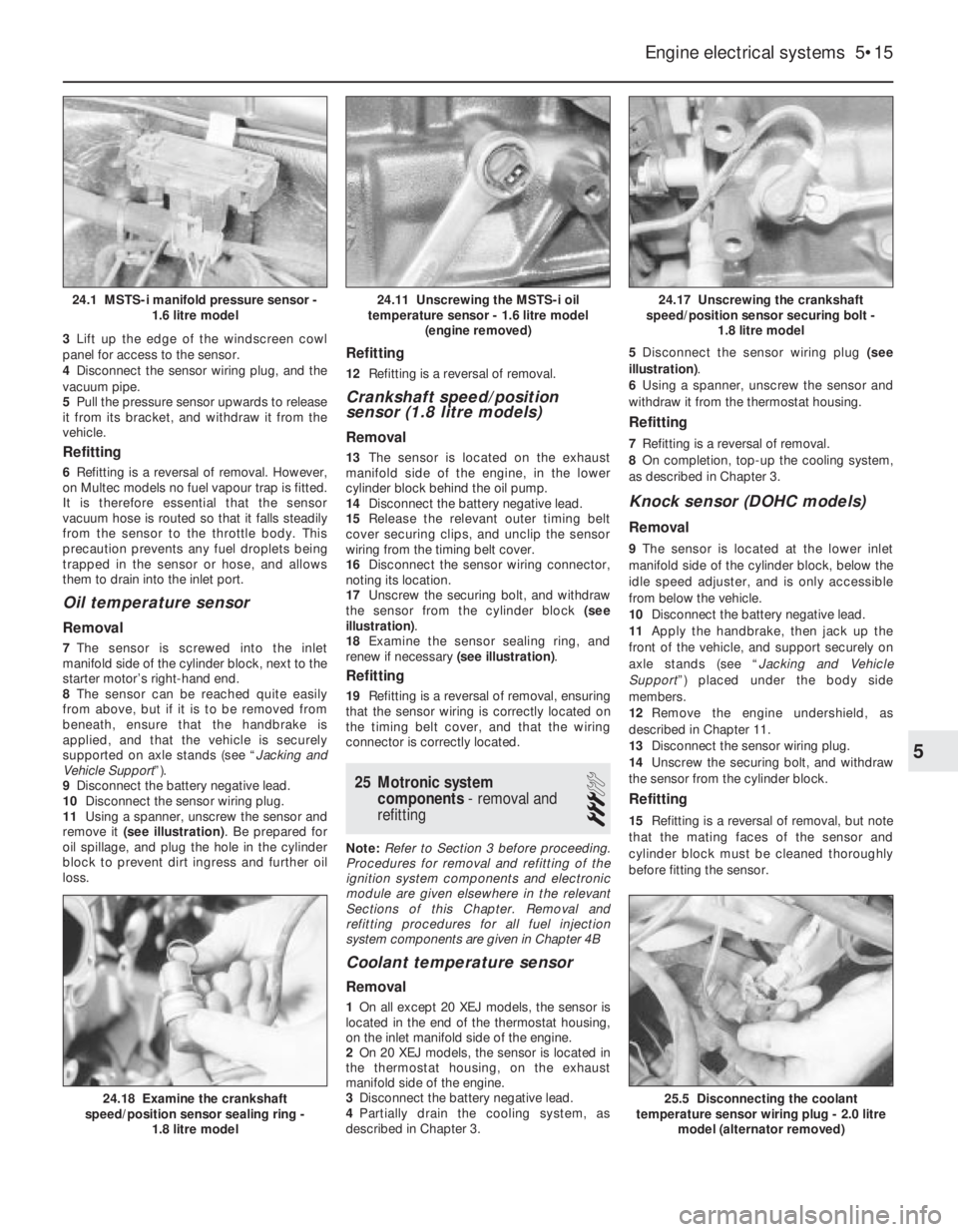
1The sensor is located on the engine
compartment bulkhead, to the left of the
MSTS-i module, under the edge of the
windscreen cowl panel (see illustration).
2Disconnect the battery negative lead.
5•14Engine electrical systems
22.3 Octane coding plug (arrowed) -
2.0 litre model
23.15 Lowering the Motronic module from
the footwell - 2.0 litre model23.16 Releasing the Motronic module
wiring plug clip - 2.0 litre model
23.6 MSTS-i module location -
1.6 litre model
Page 102 of 525
3Lift up the edge of the windscreen cowl
panel for access to the sensor.
4Disconnect the sensor wiring plug, and the
vacuum pipe.
5Pull the pressure sensor upwards to release
it from its bracket, and withdraw it from the
vehicle.
Refitting
6Refitting is a reversal of removal. However,
on Multec models no fuel vapour trap is fitted.
It is therefore essential that the sensor
vacuum hose is routed so that it falls steadily
from the sensor to the throttle body. This
precaution prevents any fuel droplets being
trapped in the sensor or hose, and allows
them to drain into the inlet port.
Oil temperature sensor
Removal
7The sensor is screwed into the inlet
manifold side of the cylinder block, next to the
starter motor’s right-hand end.
8The sensor can be reached quite easily
from above, but if it is to be removed from
beneath, ensure that the handbrake is
applied, and that the vehicle is securely
supported on axle stands (see “Jacking and
Vehicle Support”).
9Disconnect the battery negative lead.
10Disconnect the sensor wiring plug.
11Using a spanner, unscrew the sensor and
remove it (see illustration). Be prepared for
oil spillage, and plug the hole in the cylinder
block to prevent dirt ingress and further oil
loss.
Refitting
12Refitting is a reversal of removal.
Crankshaft speed/position
sensor (1.8 litre models)
Removal
13The sensor is located on the exhaust
manifold side of the engine, in the lower
cylinder block behind the oil pump.
14Disconnect the battery negative lead.
15Release the relevant outer timing belt
cover securing clips, and unclip the sensor
wiring from the timing belt cover.
16Disconnect the sensor wiring connector,
noting its location.
17Unscrew the securing bolt, and withdraw
the sensor from the cylinder block (see
illustration).
18Examine the sensor sealing ring, and
renew if necessary (see illustration).
Refitting
19Refitting is a reversal of removal, ensuring
that the sensor wiring is correctly located on
the timing belt cover, and that the wiring
connector is correctly located.
25Motronic system
components - removal and
refitting
3
Note: Refer to Section 3 before proceeding.
Procedures for removal and refitting of the
ignition system components and electronic
module are given elsewhere in the relevant
Sections of this Chapter. Removal and
refitting procedures for all fuel injection
system components are given in Chapter 4B
Coolant temperature sensor
Removal
1On all except 20 XEJ models, the sensor is
located in the end of the thermostat housing,
on the inlet manifold side of the engine.
2On 20 XEJ models, the sensor is located in
the thermostat housing, on the exhaust
manifold side of the engine.
3Disconnect the battery negative lead.
4Partially drain the cooling system, as
described in Chapter 3. 5Disconnect the sensor wiring plug (see
illustration).
6Using a spanner, unscrew the sensor and
withdraw it from the thermostat housing.
Refitting
7Refitting is a reversal of removal.
8On completion, top-up the cooling system,
as described in Chapter 3.
Knock sensor (DOHC models)
Removal
9The sensor is located at the lower inlet
manifold side of the cylinder block, below the
idle speed adjuster, and is only accessible
from below the vehicle.
10Disconnect the battery negative lead.
11Apply the handbrake, then jack up the
front of the vehicle, and support securely on
axle stands (see “Jacking and Vehicle
Support”) placed under the body side
members.
12Remove the engine undershield, as
described in Chapter 11.
13Disconnect the sensor wiring plug.
14Unscrew the securing bolt, and withdraw
the sensor from the cylinder block.
Refitting
15Refitting is a reversal of removal, but note
that the mating faces of the sensor and
cylinder block must be cleaned thoroughly
before fitting the sensor.
Engine electrical systems 5•15
24.17 Unscrewing the crankshaft
speed/position sensor securing bolt -
1.8 litre model
25.5 Disconnecting the coolant
temperature sensor wiring plug - 2.0 litre
model (alternator removed)24.18 Examine the crankshaft
speed/position sensor sealing ring -
1.8 litre model
24.11 Unscrewing the MSTS-i oil
temperature sensor - 1.6 litre model
(engine removed)24.1 MSTS-i manifold pressure sensor -
1.6 litre model
5