1988 OPEL VECTRA service
[x] Cancel search: servicePage 174 of 525
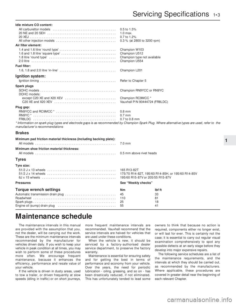
Idle mixture CO content:
All carburettor models . . . . . . . . . . . . . . . . . . . . . . . . . . . . . . . . . . . .0.5 to 1.5%
20 NE and 20 SEH . . . . . . . . . . . . . . . . . . . . . . . . . . . . . . . . . . . . . . .1.0 max.
20 XEJ . . . . . . . . . . . . . . . . . . . . . . . . . . . . . . . . . . . . . . . . . . . . . . . . .0.7 to 1.2%
All other injection models . . . . . . . . . . . . . . . . . . . . . . . . . . . . . . . . . .0.3 % (at 2800 to 3200 rpm)
Air filter element:
1.4 and 1.6 litre ‘round type’ . . . . . . . . . . . . . . . . . . . . . . . . . . . . . . . .Champion W103
1.6 and 1.8 litre ‘square type’ . . . . . . . . . . . . . . . . . . . . . . . . . . . . . . .Champion U512
1.8 litre ‘round type’ . . . . . . . . . . . . . . . . . . . . . . . . . . . . . . . . . . . . . .Champion type not available
2.0 litre . . . . . . . . . . . . . . . . . . . . . . . . . . . . . . . . . . . . . . . . . . . . . . . .Champion U554
Fuel filter:
1.6, 1.8 and 2.0 litre ‘in-line’ . . . . . . . . . . . . . . . . . . . . . . . . . . . . . . . .Champion L201
Ignition system:
Ignition timing . . . . . . . . . . . . . . . . . . . . . . . . . . . . . . . . . . . . . . . . . . .Refer to Chapter 5
Spark plugs
SOHC models . . . . . . . . . . . . . . . . . . . . . . . . . . . . . . . . . . . . . . . . . . .Champion RN9YCC or RN9YC
DOHC models:
except C20 XE and X20 XEV . . . . . . . . . . . . . . . . . . . . . . . . . . . . .Champion RC9MCC *
C20 XE and X20 XEV . . . . . . . . . . . . . . . . . . . . . . . . . . . . . . . . . . .Vauxhall P/N 90444724 (FR8LDC)
Plug gap:
RN9YCC and RC9MCC * . . . . . . . . . . . . . . . . . . . . . . . . . . . . . . . . . .0.8 mm
RN9YC * . . . . . . . . . . . . . . . . . . . . . . . . . . . . . . . . . . . . . . . . . . . . . . .0.7 mm
FR8LDC . . . . . . . . . . . . . . . . . . . . . . . . . . . . . . . . . . . . . . . . . . . . . . .0.7 to 0.8 mm
* Information on spark plug types and electrode gaps is as recommended by Champion Spark Plug. Where alternative types are used, refer to the
manufacturer’s recommendations
Brakes
Minimum pad friction material thickness (including backing plate):
All models . . . . . . . . . . . . . . . . . . . . . . . . . . . . . . . . . . . . . . . . . . . . . .7.0 mm
Minimum shoe friction material thickness:
All models . . . . . . . . . . . . . . . . . . . . . . . . . . . . . . . . . . . . . . . . . . . . . .0.5 mm above rivet heads
Tyres
Tyre size:
51/2 J x 13 wheels . . . . . . . . . . . . . . . . . . . . . . . . . . . . . . . . . . . . . . .165 R13-82T
51/2 J x 14 wheels . . . . . . . . . . . . . . . . . . . . . . . . . . . . . . . . . . . . . . .175/70 R14-82T, 195/60 R14-85H, or 195/60 R14-85V
6J x 15 wheels . . . . . . . . . . . . . . . . . . . . . . . . . . . . . . . . . . . . . . . . . .195/60 R15-87V or 205/55 R15-87V
PressuresSee “Weekly checks”
Torque wrench settingsNmlbf ft
Automatic transmission drain plug . . . . . . . . . . . . . . . . . . . . . . . . . . . . .4533
Roadwheel . . . . . . . . . . . . . . . . . . . . . . . . . . . . . . . . . . . . . . . . . . . . . . .11081
Spark plugs . . . . . . . . . . . . . . . . . . . . . . . . . . . . . . . . . . . . . . . . . . . . . . .2518
Engine oil (sump) drain plug . . . . . . . . . . . . . . . . . . . . . . . . . . . . . . . . .5541
Servicing Specifications 1•3
1
The maintenance intervals in this manual
are provided with the assumption that you,
not the dealer, will be carrying out the work.
These are the minimum maintenance intervals
recommended by the manufacturer for
vehicles driven daily. If you wish to keep your
vehicle in peak condition at all times, you may
wish to perform some of these procedures
more often. We encourage frequent
maintenance, because it enhances the
efficiency, performance and resale value of
your vehicle.
If the vehicle is driven in dusty areas, used
to tow a trailer, or driven frequently at slow
speeds (idling in traffic) or on short journeys,more frequent maintenance intervals are
recommended. Vauxhall recommend that the
service intervals are halved for vehicles that
are used under these conditions.
When the vehicle is new, it should be
serviced by a factory-authorised dealer
service department, to preserve the factory
warranty.
Maintenance is essential for ensuring safety
and for getting the best in terms of
performance and economy from your vehicle.
Over the years, the need for periodic
lubrication -oiling, greasing, and so on -has
been drastically reduced, if not eliminated.
This has unfortunately tended to lead someowners to think that because no action is
required, components either no longer exist,
or will last for ever. This is certainly not the
case; it is essential to carry out regular visual
examination comprehensively to spot any
possible defects at an early stage before they
develop into major expensive repairs.
The following service schedules are a list of
the maintenance requirements, and the
intervals at which they should be carried out,
as recommended by the manufacturers.
Where applicable, these procedures are
covered in greater detail near the beginning of
each relevant Chapter.
Maintenance schedule
Page 175 of 525
1•4Maintenance schedule
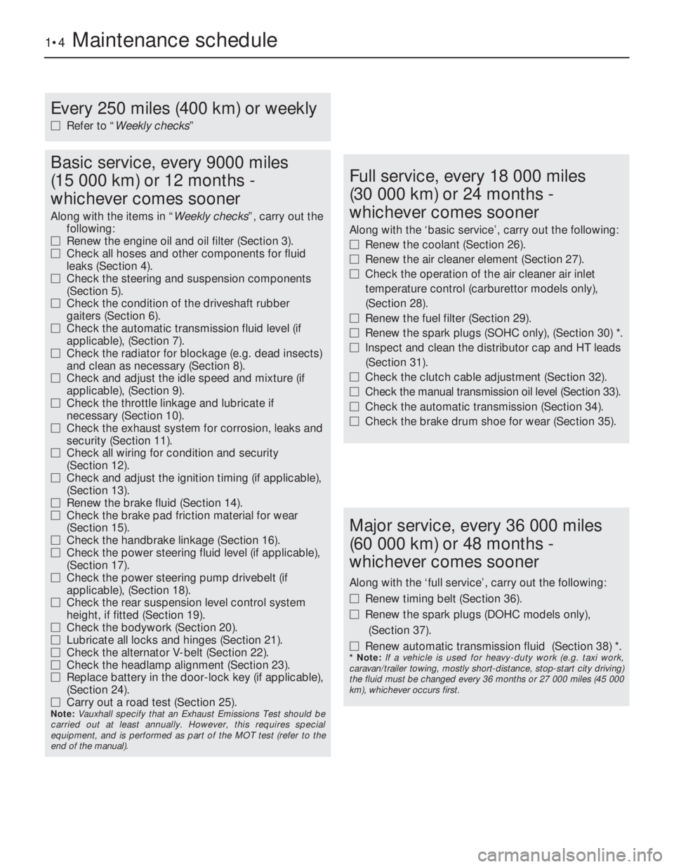
Every 250 miles (400 km) or weekly
MRefer to “Weekly checks”
Basic service, every 9000 miles
(15 000 km) or 12 months -
whichever comes sooner
Along with the items in “Weekly checks”, carry out the
following:
MRenew the engine oil and oil filter (Section 3).
MCheck all hoses and other components for fluid
leaks (Section 4).
MCheck the steering and suspension components
(Section 5).
MCheck the condition of the driveshaft rubber
gaiters (Section 6).
MCheck the automatic transmission fluid level (if
applicable), (Section 7).
MCheck the radiator for blockage (e.g. dead insects)
and clean as necessary (Section 8).
MCheck and adjust the idle speed and mixture (if
applicable), (Section 9).
MCheck the throttle linkage and lubricate if
necessary (Section 10).
MCheck the exhaust system for corrosion, leaks and
security (Section 11).
MCheck all wiring for condition and security
(Section 12).
MCheck and adjust the ignition timing (if applicable),
(Section 13).
MRenew the brake fluid (Section 14).
MCheck the brake pad friction material for wear
(Section 15).
MCheck the handbrake linkage (Section 16).
MCheck the power steering fluid level (if applicable),
(Section 17).
MCheck the power steering pump drivebelt (if
applicable), (Section 18).
MCheck the rear suspension level control system
height, if fitted (Section 19).
MCheck the bodywork (Section 20).
MLubricate all locks and hinges (Section 21).
MCheck the alternator V-belt (Section 22).
MCheck the headlamp alignment (Section 23).
MReplace battery in the door-lock key (if applicable),
(Section 24).
MCarry out a road test (Section 25).
Note: Vauxhall specify that an Exhaust Emissions Test should be
carried out at least annually. However, this requires special
equipment, and is performed as part of the MOT test (refer to the
end of the manual).
Full service, every 18 000 miles
(30 000 km) or 24 months -
whichever comes sooner
Along with the ‘basic service’, carry out the following:
MRenew the coolant (Section 26).
MRenew the air cleaner element (Section 27).
MCheck the operation of the air cleaner air inlet
temperature control (carburettor models only),
(Section 28).
MRenew the fuel filter (Section 29).
MRenew the spark plugs (SOHC only), (Section 30) *.
MInspect and clean the distributor cap and HT leads
(Section 31).
MCheck the clutch cable adjustment (Section 32).
MCheck the manual transmission oil level (Section 33).
MCheck the automatic transmission (Section 34).
MCheck the brake drum shoe for wear (Section 35).
Major service, every 36 000 miles
(60 000 km) or 48 months -
whichever comes sooner
Along with the ‘full service’, carry out the following:
MRenew timing belt (Section 36).
MRenew the spark plugs (DOHC models only),
(Section 37).
MRenew automatic transmission fluid (Section 38) *.
* Note: If a vehicle is used for heavy-duty work (e.g. taxi work,
caravan/trailer towing, mostly short-distance, stop-start city driving)
the fluid must be changed every 36 months or 27 000 miles (45 000
km), whichever occurs first.
Page 179 of 525

1Introduction
This Chapter is designed to help the home
mechanic maintain his/her vehicle for safety,
economy, long life and peak performance.
The Chapter contains a master maintenance
schedule, followed by Sections dealing specifically
with each task in the schedule. Visual checks,
adjustments, component renewal and other helpful
items are included. Refer to the accompanying
illustrations of the engine compartment and the
underside of the vehicle for the locations of the
various components.
Servicing your vehicle according to the
mileage/time maintenance schedule and the
following Sections will provide a planned
maintenance programme, which should result in a
long and reliable service life. This is a comprehensiveplan, so maintaining some items but not others at
the specified service intervals, will not produce the
same results.
As you service your vehicle, you will
discover that many of the procedures can -
and should - be grouped together, because of
the particular procedure being performed, or
because of the proximity of two otherwise-
unrelated components to one another. For
example, if the vehicle is raised for any
reason, the exhaust can be inspected at the
same time as the suspension and steering
components.
The first step in this maintenance
programme is to prepare yourself before the
actual work begins. Read through all the
Sections relevant to the work to be carried
out, then make a list and gather all the parts
and tools required. If a problem is found, seek
advice from a parts specialist, or a dealer
service department.
2Intensive maintenance
If, from the time the vehicle is new, routine
maintenance schedule is followed closely,
frequent checks made of fluid levels and high-
wear items, as recommended, the engine will
be kept in relatively good running condition.
The need for additional work will be minimised
It is possible that there will be times when
the engine is running poorly due to the lack of
regular maintenance. This is even more likely
if a used vehicle, which has not received
regular and frequent maintenance checks, is
purchased. In such cases, additional work
may need to be carried out, outside of the
regular maintenance intervals.
If engine wear is suspected, a compression
1•8Maintenance - component location
Rear underbody view of a 1990 GSi 2000 model (fully independent rear suspension)
1 Fuel tank securing strap
2 Shock absorber
3 ABS wheel sensor
4 Semi-trailing arm
5 Suspension crossmember
mounting bracing bracket
6 Handbrake cable
7 Suspension crossmember
8 Exhaust expansion box
9 Fuel pump
Maintenance procedures
Page 180 of 525
test (refer to Chapter 2A) will provide valuable
information regarding the overall performance
of the main internal components. Such a test
can be used as a basis to decide on the
extent of the work to be carried out. If, for
example, a compression test indicates serious
internal engine wear, conventional
maintenance as described in this Chapter will
not greatly improve the performance of the
engine. It may also prove a waste of time and
money, unless extensive overhaul work is
carried out first.
The following series of operations are those
most often required to improve the
performance of a generally poor-running
engine:Primary operations
a)Clean, inspect and test the battery (See
“Weekly Checks”)
b)Check all the engine related fluids (See
“Weekly Checks”)
c)Check the condition and tension of the
auxiliary drivebelt (Sections 18 and 22, as
appropriate).
d)Renew the spark plugs (Sections 30 and
37, as appropriate).
e)Inspect the distributor cap, rotor arm and
HT leads, as applicable (Section 31).
f)Check the condition of the air filter, and
renew if necessary (Section 27).
g)Check the fuel filter (Section 29).
h)Check the condition of all hoses, and
check for fluid leaks (Section 4).i)Check the idle speed and mixture
settings, as applicable (Section 9).
5If the above operations do not prove fully
effective, carry out the following secondary
operations:
Secondary operations
All items listed under “Primary operations”,
plus the following:
a)Check the charging system (Chapter 5).
b)Check the ignition system (Chapter 5).
c)Check the fuel system (Chapters 4A and
4B).
d)Renew the distributor cap and rotor arm
(Section 31).
e)Renew the ignition HT leads (Section 31).
3Engine oil and filter - renewal
2
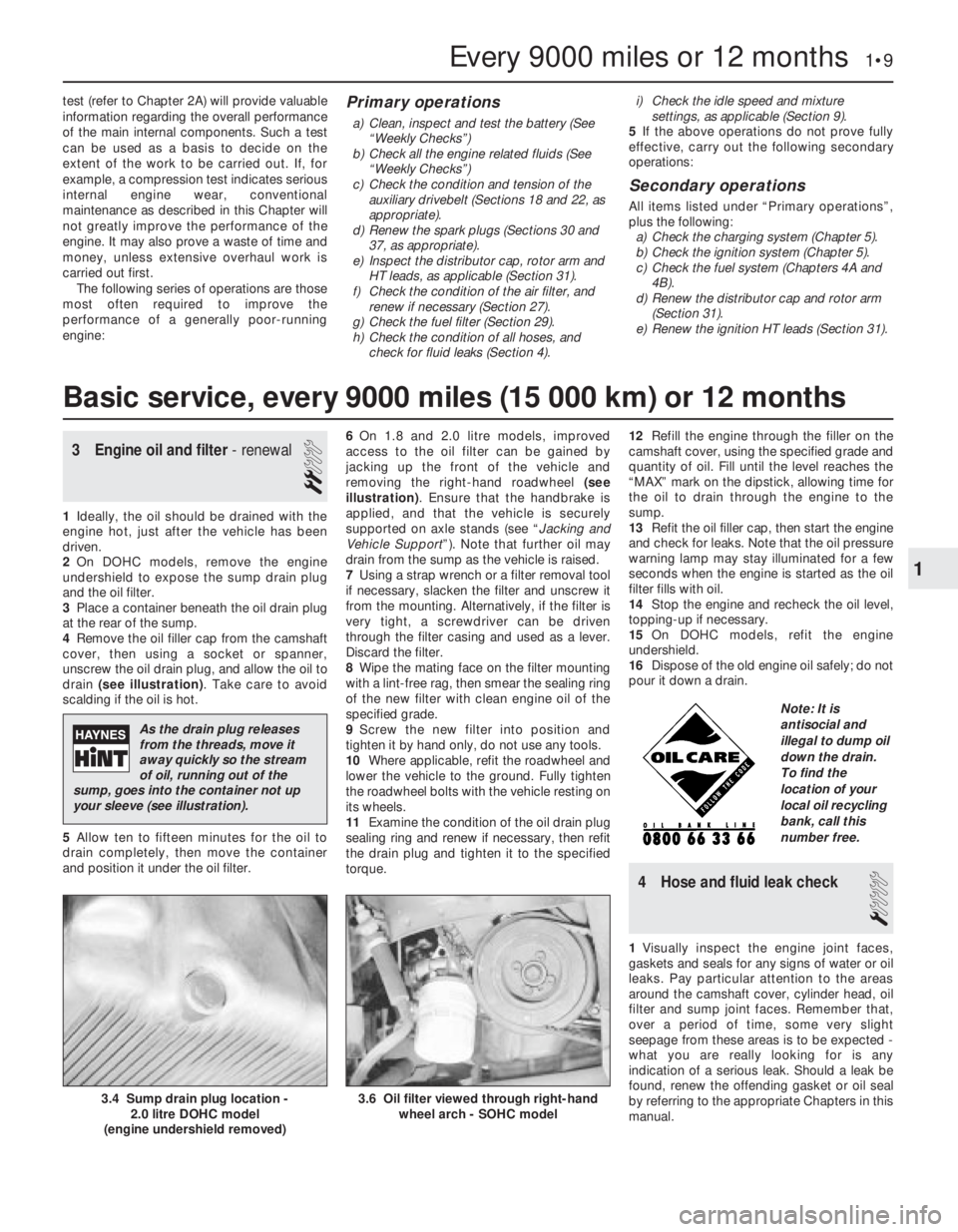
1Ideally, the oil should be drained with the
engine hot, just after the vehicle has been
driven.
2On DOHC models, remove the engine
undershield to expose the sump drain plug
and the oil filter.
3Place a container beneath the oil drain plug
at the rear of the sump.
4Remove the oil filler cap from the camshaft
cover, then using a socket or spanner,
unscrew the oil drain plug, and allow the oil to
drain (see illustration). Take care to avoid
scalding if the oil is hot.
5Allow ten to fifteen minutes for the oil to
drain completely, then move the container
and position it under the oil filter.6On 1.8 and 2.0 litre models, improved
access to the oil filter can be gained by
jacking up the front of the vehicle and
removing the right-hand roadwheel (see
illustration). Ensure that the handbrake is
applied, and that the vehicle is securely
supported on axle stands (see “Jacking and
Vehicle Support”). Note that further oil may
drain from the sump as the vehicle is raised.
7Using a strap wrench or a filter removal tool
if necessary, slacken the filter and unscrew it
from the mounting. Alternatively, if the filter is
very tight, a screwdriver can be driven
through the filter casing and used as a lever.
Discard the filter.
8Wipe the mating face on the filter mounting
with a lint-free rag, then smear the sealing ring
of the new filter with clean engine oil of the
specified grade.
9Screw the new filter into position and
tighten it by hand only, do not use any tools.
10Where applicable, refit the roadwheel and
lower the vehicle to the ground. Fully tighten
the roadwheel bolts with the vehicle resting on
its wheels.
11Examine the condition of the oil drain plug
sealing ring and renew if necessary, then refit
the drain plug and tighten it to the specified
torque. 12Refill the engine through the filler on the
camshaft cover, using the specified grade and
quantity of oil. Fill until the level reaches the
“MAX” mark on the dipstick, allowing time for
the oil to drain through the engine to the
sump.
13Refit the oil filler cap, then start the engine
and check for leaks. Note that the oil pressure
warning lamp may stay illuminated for a few
seconds when the engine is started as the oil
filter fills with oil.
14Stop the engine and recheck the oil level,
topping-up if necessary.
15On DOHC models, refit the engine
undershield.
16Dispose of the old engine oil safely; do not
pour it down a drain.
4Hose and fluid leak check
1
1Visually inspect the engine joint faces,
gaskets and seals for any signs of water or oil
leaks. Pay particular attention to the areas
around the camshaft cover, cylinder head, oil
filter and sump joint faces. Remember that,
over a period of time, some very slight
seepage from these areas is to be expected -
what you are really looking for is any
indication of a serious leak. Should a leak be
found, renew the offending gasket or oil seal
by referring to the appropriate Chapters in this
manual.
Every 9000 miles or 12 months 1•9
3.6 Oil filter viewed through right-hand
wheel arch - SOHC model3.4 Sump drain plug location -
2.0 litre DOHC model
(engine undershield removed)
1
Basic service, every 9000 miles (15 000 km) or 12 months
As the drain plug releases
from the threads, move it
away quickly so the stream
of oil, running out of the
sump, goes into the container not up
your sleeve (see illustration).
Note: It is
antisocial and
illegal to dump oil
down the drain.
To find the
location of your
local oil recycling
bank, call this
number free.
Page 184 of 525
tighten the mounting nuts and bolts. On no
account lever at the free end of the alternator,
as serious internal damage could be caused.
3For details of replacement, see Chapter 5.
23Headlamp alignment
2
Refer to Chapter 12 for details.
24Door lock key battery -
replacement
1
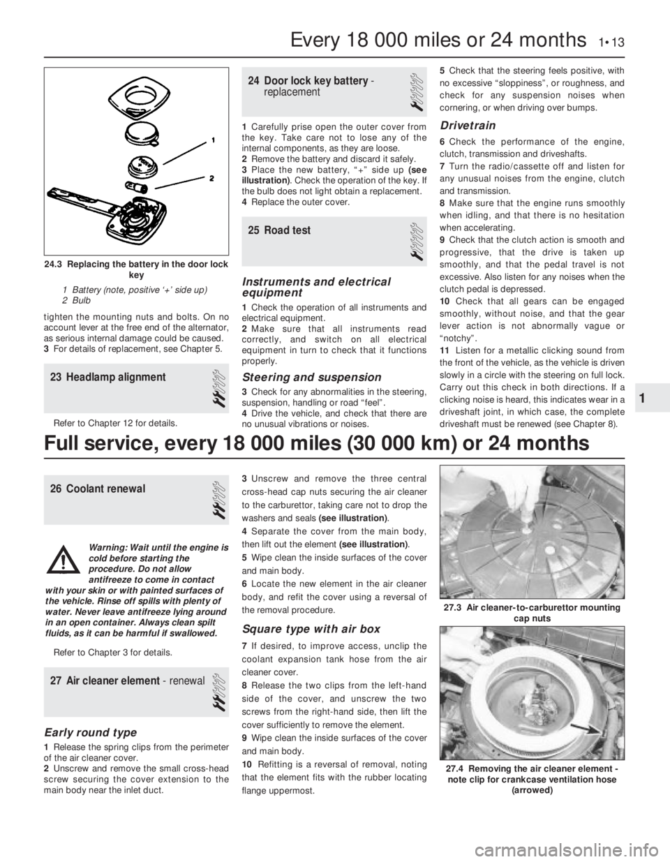
1Carefully prise open the outer cover from
the key. Take care not to lose any of the
internal components, as they are loose.
2Remove the battery and discard it safely.
3Place the new battery, “+” side up (see
illustration). Check the operation of the key. If
the bulb does not light obtain a replacement.
4Replace the outer cover.
25Road test
1
Instruments and electrical
equipment
1Check the operation of all instruments and
electrical equipment.
2Make sure that all instruments read
correctly, and switch on all electrical
equipment in turn to check that it functions
properly.
Steering and suspension
3Check for any abnormalities in the steering,
suspension, handling or road “feel”.
4Drive the vehicle, and check that there are
no unusual vibrations or noises.5Check that the steering feels positive, with
no excessive “sloppiness”, or roughness, and
check for any suspension noises when
cornering, or when driving over bumps.
Drivetrain
6Check the performance of the engine,
clutch, transmission and driveshafts.
7Turn the radio/cassette off and listen for
any unusual noises from the engine, clutch
and transmission.
8Make sure that the engine runs smoothly
when idling, and that there is no hesitation
when accelerating.
9Check that the clutch action is smooth and
progressive, that the drive is taken up
smoothly, and that the pedal travel is not
excessive. Also listen for any noises when the
clutch pedal is depressed.
10Check that all gears can be engaged
smoothly, without noise, and that the gear
lever action is not abnormally vague or
“notchy”.
11Listen for a metallic clicking sound from
the front of the vehicle, as the vehicle is driven
slowly in a circle with the steering on full lock.
Carry out this check in both directions. If a
clicking noise is heard, this indicates wear in a
driveshaft joint, in which case, the complete
driveshaft must be renewed (see Chapter 8).
26Coolant renewal
2
Refer to Chapter 3 for details.
27Air cleaner element - renewal
2
Early round type
1Release the spring clips from the perimeter
of the air cleaner cover.
2Unscrew and remove the small cross-head
screw securing the cover extension to the
main body near the inlet duct.3Unscrew and remove the three central
cross-head cap nuts securing the air cleaner
to the carburettor, taking care not to drop the
washers and seals (see illustration).
4Separate the cover from the main body,
then lift out the element (see illustration).
5Wipe clean the inside surfaces of the cover
and main body.
6Locate the new element in the air cleaner
body, and refit the cover using a reversal of
the removal procedure.
Square type with air box
7If desired, to improve access, unclip the
coolant expansion tank hose from the air
cleaner cover.
8Release the two clips from the left-hand
side of the cover, and unscrew the two
screws from the right-hand side, then lift the
cover sufficiently to remove the element.
9Wipe clean the inside surfaces of the cover
and main body.
10Refitting is a reversal of removal, noting
that the element fits with the rubber locating
flange uppermost.
Every 18 000 miles or 24 months 1•13
24.3 Replacing the battery in the door lock
key
1 Battery (note, positive ‘+’ side up)
2 Bulb
27.4 Removing the air cleaner element -
note clip for crankcase ventilation hose
(arrowed)
27.3 Air cleaner-to-carburettor mounting
cap nuts
1
Full service, every 18 000 miles (30 000 km) or 24 months
Warning: Wait until the engine is
cold before starting the
procedure. Do not allow
antifreeze to come in contact
with your skin or with painted surfaces of
the vehicle. Rinse off spills with plenty of
water. Never leave antifreeze lying around
in an open container. Always clean spilt
fluids, as it can be harmful if swallowed.
Page 185 of 525
28Air inlet temperature control
check (carburettor models
only)
2
Refer to Chapter 4A for details.
29Fuel filter renewal
3
Fuel filters are fitted in various locations
throughout the range. Some may be ‘in-line’ in
the fuel tank itself, or fitted into the
carburettor.
Refer to Chapters 4A or 4B, as appropriate.
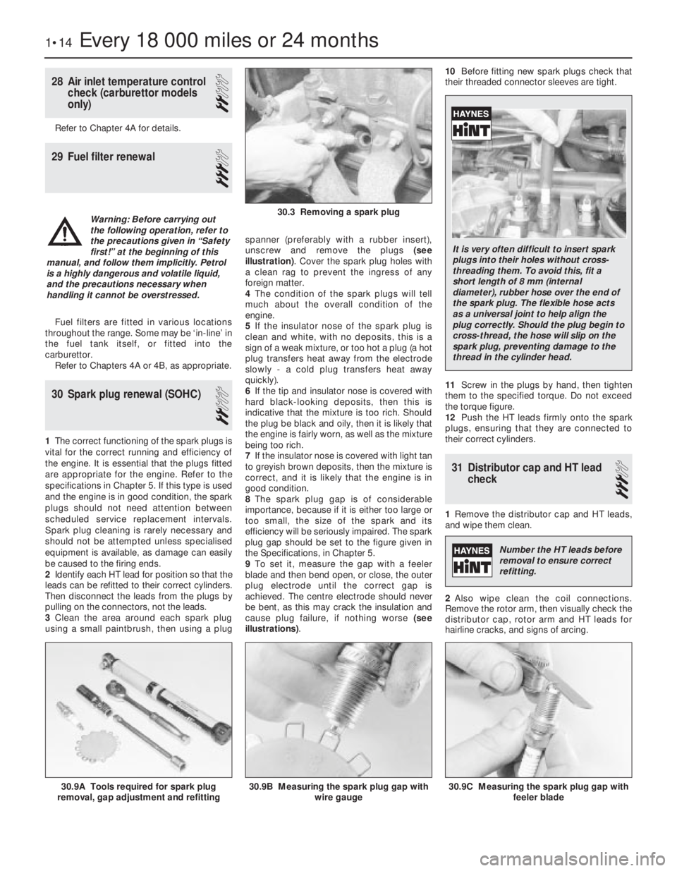
30Spark plug renewal (SOHC)
2
1The correct functioning of the spark plugs is
vital for the correct running and efficiency of
the engine. It is essential that the plugs fitted
are appropriate for the engine. Refer to the
specifications in Chapter 5. If this type is used
and the engine is in good condition, the spark
plugs should not need attention between
scheduled service replacement intervals.
Spark plug cleaning is rarely necessary and
should not be attempted unless specialised
equipment is available, as damage can easily
be caused to the firing ends.
2Identify each HT lead for position so that the
leads can be refitted to their correct cylinders.
Then disconnect the leads from the plugs by
pulling on the connectors, not the leads.
3Clean the area around each spark plug
using a small paintbrush, then using a plugspanner (preferably with a rubber insert),
unscrew and remove the plugs (see
illustration). Cover the spark plug holes with
a clean rag to prevent the ingress of any
foreign matter.
4The condition of the spark plugs will tell
much about the overall condition of the
engine.
5If the insulator nose of the spark plug is
clean and white, with no deposits, this is a
sign of a weak mixture, or too hot a plug (a hot
plug transfers heat away from the electrode
slowly -a cold plug transfers heat away
quickly).
6If the tip and insulator nose is covered with
hard black-looking deposits, then this is
indicative that the mixture is too rich. Should
the plug be black and oily, then it is likely that
the engine is fairly worn, as well as the mixture
being too rich.
7If the insulator nose is covered with light tan
to greyish brown deposits, then the mixture is
correct, and it is likely that the engine is in
good condition.
8The spark plug gap is of considerable
importance, because if it is either too large or
too small, the size of the spark and its
efficiency will be seriously impaired. The spark
plug gap should be set to the figure given in
the Specifications, in Chapter 5.
9To set it, measure the gap with a feeler
blade and then bend open, or close, the outer
plug electrode until the correct gap is
achieved. The centre electrode should never
be bent, as this may crack the insulation and
cause plug failure, if nothing worse (see
illustrations).10Before fitting new spark plugs check that
their threaded connector sleeves are tight.
11Screw in the plugs by hand, then tighten
them to the specified torque. Do not exceed
the torque figure.
12Push the HT leads firmly onto the spark
plugs, ensuring that they are connected to
their correct cylinders.
31Distributor cap and HT lead
check
3
1Remove the distributor cap and HT leads,
and wipe them clean.
2Also wipe clean the coil connections.
Remove the rotor arm, then visually check the
distributor cap, rotor arm and HT leads for
hairline cracks, and signs of arcing.
1•14Every 18 000 miles or 24 months
30.9A Tools required for spark plug
removal, gap adjustment and refitting30.9C Measuring the spark plug gap with
feeler blade30.9B Measuring the spark plug gap with
wire gauge
30.3 Removing a spark plugWarning: Before carrying out
the following operation, refer to
the precautions given in “Safety
first!” at the beginning of this
manual, and follow them implicitly. Petrol
is a highly dangerous and volatile liquid,
and the precautions necessary when
handling it cannot be overstressed.
It is very often difficult to insert spark
plugs into their holes without cross-
threading them. To avoid this, fit a
short length of 8 mm (internal
diameter), rubber hose over the end of
the spark plug. The flexible hose acts
as a universal joint to help align the
plug correctly. Should the plug begin to
cross-thread, the hose will slip on the
spark plug, preventing damage to the
thread in the cylinder head.
Number the HT leads before
removal to ensure correct
refitting.
Page 187 of 525
36Timing belt renewal
3
1To minimise risk of major damage to the
engine the timing belt (or cambelt, as it is
sometimes called), needs replacing at least,
on every major service.
2It is good practise however, not only to
renew the belt whenever major engine work is
carried out, but also if you buy a used car with
unclear service history.
3Some models are fitted with an inspection
cover to view the condition of the belt. Whilst
others involve a lot more work.
4Full details on checking and replacement
are shown in Chapters 2A or 2B, as
appropriate.
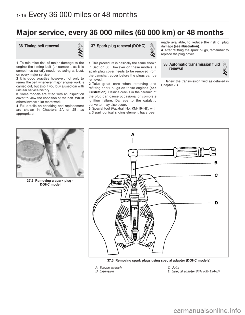
37Spark plug renewal (DOHC)
2
1This procedure is basically the same shown
in Section 30. However on these models, a
spark plug cover needs to be removed from
the camshaft cover before the plugs can be
removed.
2Take great care when removing and
refitting spark plugs on these engines (see
illustration). Hairline cracks in the ceramic of
the plug can cause occasional or complete
ignition failure. Damage to the catalytic
converter may also occur.
3Special tool (Vauxhall No. KM-194-B), with
a 3 part conical sliding element have beenmade available, to reduce the risk of plug
damage (see illustration).
4After refitting the spark plugs, remember to
replace the plug cover.38Automatic transmission fluid
renewal
2
Renew the transmission fluid as detailed in
Chapter 7B.
1•16Every 36 000 miles or 48 months
37.3 Removing spark plugs using special adapter (DOHC models)
A Torque wrench
B ExtensionC Joint
D Special adapter (P/N KM-194-B)
37.2 Removing a spark plug -
DOHC model
Major service, every 36 000 miles (60 000 km) or 48 months
Page 189 of 525
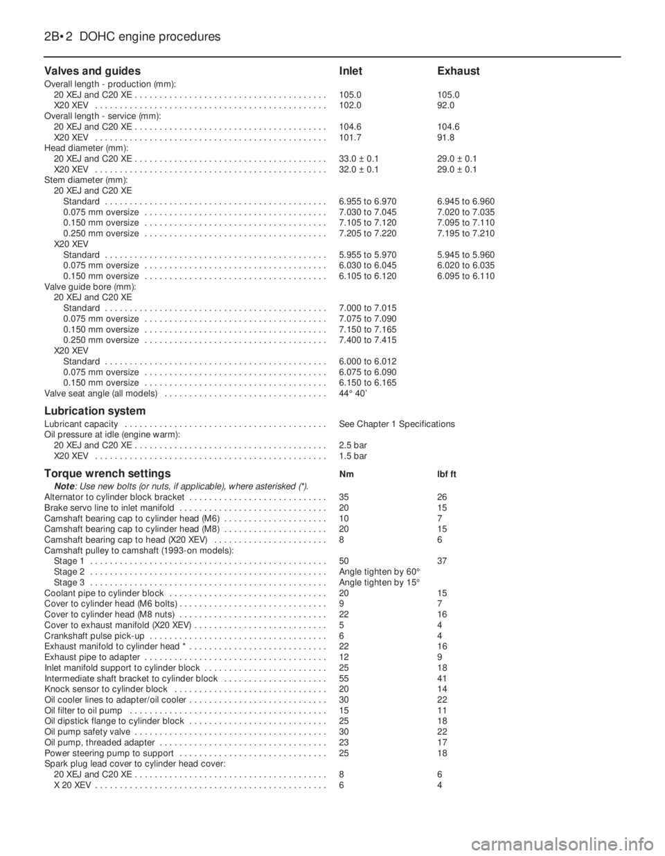
Valves and guidesInletExhaust
Overall length - production (mm):
20 XEJ and C20 XE . . . . . . . . . . . . . . . . . . . . . . . . . . . . . . . . . . . . . . .105.0105.0
X20 XEV . . . . . . . . . . . . . . . . . . . . . . . . . . . . . . . . . . . . . . . . . . . . . . .102.092.0
Overall length - service (mm):
20 XEJ and C20 XE . . . . . . . . . . . . . . . . . . . . . . . . . . . . . . . . . . . . . . .104.6104.6
X20 XEV . . . . . . . . . . . . . . . . . . . . . . . . . . . . . . . . . . . . . . . . . . . . . . .101.791.8
Head diameter (mm):
20 XEJ and C20 XE . . . . . . . . . . . . . . . . . . . . . . . . . . . . . . . . . . . . . . .33.0 ±0.129.0 ±0.1
X20 XEV . . . . . . . . . . . . . . . . . . . . . . . . . . . . . . . . . . . . . . . . . . . . . . .32.0 ±0.129.0 ±0.1
Stem diameter (mm):
20 XEJ and C20 XE
Standard . . . . . . . . . . . . . . . . . . . . . . . . . . . . . . . . . . . . . . . . . . . . .6.955 to 6.9706.945 to 6.960
0.075 mm oversize . . . . . . . . . . . . . . . . . . . . . . . . . . . . . . . . . . . . .7.030 to 7.0457.020 to 7.035
0.150 mm oversize . . . . . . . . . . . . . . . . . . . . . . . . . . . . . . . . . . . . .7.105 to 7.1207.095 to 7.110
0.250 mm oversize . . . . . . . . . . . . . . . . . . . . . . . . . . . . . . . . . . . . .7.205 to 7.2207.195 to 7.210
X20 XEV
Standard . . . . . . . . . . . . . . . . . . . . . . . . . . . . . . . . . . . . . . . . . . . . .5.955 to 5.9705.945 to 5.960
0.075 mm oversize . . . . . . . . . . . . . . . . . . . . . . . . . . . . . . . . . . . . .6.030 to 6.0456.020 to 6.035
0.150 mm oversize . . . . . . . . . . . . . . . . . . . . . . . . . . . . . . . . . . . . .6.105 to 6.1206.095 to 6.110
Valve guide bore (mm):
20 XEJ and C20 XE
Standard . . . . . . . . . . . . . . . . . . . . . . . . . . . . . . . . . . . . . . . . . . . . .7.000 to 7.015
0.075 mm oversize . . . . . . . . . . . . . . . . . . . . . . . . . . . . . . . . . . . . .7.075 to 7.090
0.150 mm oversize . . . . . . . . . . . . . . . . . . . . . . . . . . . . . . . . . . . . .7.150 to 7.165
0.250 mm oversize . . . . . . . . . . . . . . . . . . . . . . . . . . . . . . . . . . . . .7.400 to 7.415
X20 XEV
Standard . . . . . . . . . . . . . . . . . . . . . . . . . . . . . . . . . . . . . . . . . . . . .6.000 to 6.012
0.075 mm oversize . . . . . . . . . . . . . . . . . . . . . . . . . . . . . . . . . . . . .6.075 to 6.090
0.150 mm oversize . . . . . . . . . . . . . . . . . . . . . . . . . . . . . . . . . . . . .6.150 to 6.165
Valve seat angle (all models) . . . . . . . . . . . . . . . . . . . . . . . . . . . . . . . . .44°40’
Lubrication system
Lubricant capacity . . . . . . . . . . . . . . . . . . . . . . . . . . . . . . . . . . . . . . . . .See Chapter 1 Specifications
Oil pressure at idle (engine warm):
20 XEJ and C20 XE . . . . . . . . . . . . . . . . . . . . . . . . . . . . . . . . . . . . . . .2.5 bar
X20 XEV . . . . . . . . . . . . . . . . . . . . . . . . . . . . . . . . . . . . . . . . . . . . . . .1.5 bar
Torque wrench settingsNmlbf ft
Note: Use new bolts (or nuts, if applicable), where asterisked (*).
Alternator to cylinder block bracket . . . . . . . . . . . . . . . . . . . . . . . . . . . .3526
Brake servo line to inlet manifold . . . . . . . . . . . . . . . . . . . . . . . . . . . . . .2015
Camshaft bearing cap to cylinder head (M6) . . . . . . . . . . . . . . . . . . . . .107
Camshaft bearing cap to cylinder head (M8) . . . . . . . . . . . . . . . . . . . . .2015
Camshaft bearing cap to head (X20 XEV) . . . . . . . . . . . . . . . . . . . . . . .86
Camshaft pulley to camshaft (1993-on models):
Stage 1 . . . . . . . . . . . . . . . . . . . . . . . . . . . . . . . . . . . . . . . . . . . . . . . .5037
Stage 2 . . . . . . . . . . . . . . . . . . . . . . . . . . . . . . . . . . . . . . . . . . . . . . . .Angle tighten by 60°
Stage 3 . . . . . . . . . . . . . . . . . . . . . . . . . . . . . . . . . . . . . . . . . . . . . . . .Angle tighten by 15°
Coolant pipe to cylinder block . . . . . . . . . . . . . . . . . . . . . . . . . . . . . . . .2015
Cover to cylinder head (M6 bolts) . . . . . . . . . . . . . . . . . . . . . . . . . . . . . .97
Cover to cylinder head (M8 nuts) . . . . . . . . . . . . . . . . . . . . . . . . . . . . . .2216
Cover to exhaust manifold (X20 XEV) . . . . . . . . . . . . . . . . . . . . . . . . . . .54
Crankshaft pulse pick-up . . . . . . . . . . . . . . . . . . . . . . . . . . . . . . . . . . . .64
Exhaust manifold to cylinder head * . . . . . . . . . . . . . . . . . . . . . . . . . . . .2216
Exhaust pipe to adapter . . . . . . . . . . . . . . . . . . . . . . . . . . . . . . . . . . . . .129
Inlet manifold support to cylinder block . . . . . . . . . . . . . . . . . . . . . . . . .2518
Intermediate shaft bracket to cylinder block . . . . . . . . . . . . . . . . . . . . .5541
Knock sensor to cylinder block . . . . . . . . . . . . . . . . . . . . . . . . . . . . . . .2014
Oil cooler lines to adapter/oil cooler . . . . . . . . . . . . . . . . . . . . . . . . . . . .3022
Oil filter to oil pump . . . . . . . . . . . . . . . . . . . . . . . . . . . . . . . . . . . . . . . .1511
Oil dipstick flange to cylinder block . . . . . . . . . . . . . . . . . . . . . . . . . . . .2518
Oil pump safety valve . . . . . . . . . . . . . . . . . . . . . . . . . . . . . . . . . . . . . . .3022
Oil pump, threaded adapter . . . . . . . . . . . . . . . . . . . . . . . . . . . . . . . . . .2317
Power steering pump to support . . . . . . . . . . . . . . . . . . . . . . . . . . . . . .2518
Spark plug lead cover to cylinder head cover:
20 XEJ and C20 XE . . . . . . . . . . . . . . . . . . . . . . . . . . . . . . . . . . . . . . .86
X 20 XEV . . . . . . . . . . . . . . . . . . . . . . . . . . . . . . . . . . . . . . . . . . . . . . .64
2B•2DOHC engine procedures