1988 OPEL CALIBRA alternator
[x] Cancel search: alternatorPage 214 of 525
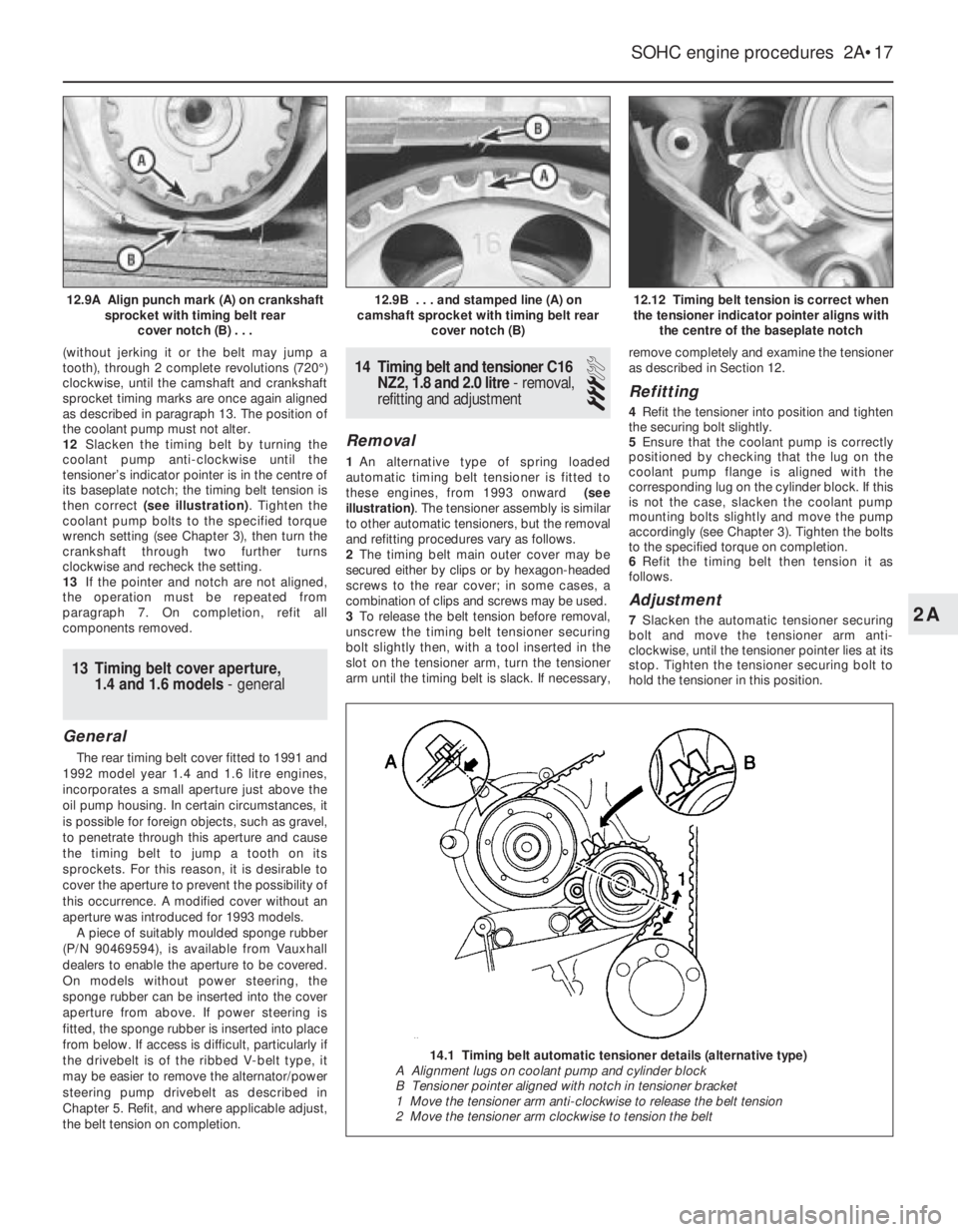
(without jerking it or the belt may jump a
tooth), through 2 complete revolutions (720°)
clockwise, until the camshaft and crankshaft
sprocket timing marks are once again aligned
as described in paragraph 13. The position of
the coolant pump must not alter.
12Slacken the timing belt by turning the
coolant pump anti-clockwise until the
tensioner’s indicator pointer is in the centre of
its baseplate notch; the timing belt tension is
then correct (see illustration). Tighten the
coolant pump bolts to the specified torque
wrench setting (see Chapter 3), then turn the
crankshaft through two further turns
clockwise and recheck the setting.
13If the pointer and notch are not aligned,
the operation must be repeated from
paragraph 7. On completion, refit all
components removed.
13Timing belt cover aperture,
1.4 and 1.6 models - general
General
The rear timing belt cover fitted to 1991 and
1992 model year 1.4 and 1.6 litre engines,
incorporates a small aperture just above the
oil pump housing. In certain circumstances, it
is possible for foreign objects, such as gravel,
to penetrate through this aperture and cause
the timing belt to jump a tooth on its
sprockets. For this reason, it is desirable to
cover the aperture to prevent the possibility of
this occurrence. A modified cover without an
aperture was introduced for 1993 models.
A piece of suitably moulded sponge rubber
(P/N 90469594), is available from Vauxhall
dealers to enable the aperture to be covered.
On models without power steering, the
sponge rubber can be inserted into the cover
aperture from above. If power steering is
fitted, the sponge rubber is inserted into place
from below. If access is difficult, particularly if
the drivebelt is of the ribbed V-belt type, it
may be easier to remove the alternator/power
steering pump drivebelt as described in
Chapter 5. Refit, and where applicable adjust,
the belt tension on completion.
14Timing belt and tensioner C16
NZ2, 1.8 and 2.0 litre - removal,
refitting and adjustment
3
Removal
1An alternative type of spring loaded
automatic timing belt tensioner is fitted to
these engines, from 1993 onward (see
illustration). The tensioner assembly is similar
to other automatic tensioners, but the removal
and refitting procedures vary as follows.
2The timing belt main outer cover may be
secured either by clips or by hexagon-headed
screws to the rear cover; in some cases, a
combination of clips and screws may be used.
3To release the belt tension before removal,
unscrew the timing belt tensioner securing
bolt slightly then, with a tool inserted in the
slot on the tensioner arm, turn the tensioner
arm until the timing belt is slack. If necessary,remove completely and examine the tensioner
as described in Section 12.
Refitting
4Refit the tensioner into position and tighten
the securing bolt slightly.
5Ensure that the coolant pump is correctly
positioned by checking that the lug on the
coolant pump flange is aligned with the
corresponding lug on the cylinder block. If this
is not the case, slacken the coolant pump
mounting bolts slightly and move the pump
accordingly (see Chapter 3). Tighten the bolts
to the specified torque on completion.
6Refit the timing belt then tension it as
follows.
Adjustment
7Slacken the automatic tensioner securing
bolt and move the tensioner arm anti-
clockwise, until the tensioner pointer lies at its
stop. Tighten the tensioner securing bolt to
hold the tensioner in this position.
SOHC engine procedures 2A•17
12.12 Timing belt tension is correct when
the tensioner indicator pointer aligns with
the centre of the baseplate notch12.9B . . . and stamped line (A) on
camshaft sprocket with timing belt rear
cover notch (B)12.9A Align punch mark (A) on crankshaft
sprocket with timing belt rear
cover notch (B) . . .
2A
14.1 Timing belt automatic tensioner details (alternative type)
A Alignment lugs on coolant pump and cylinder block
B Tensioner pointer aligned with notch in tensioner bracket
1 Move the tensioner arm anti-clockwise to release the belt tension
2 Move the tensioner arm clockwise to tension the belt
Page 217 of 525
supported to one side out of the way, thus
avoiding the need to disconnect the relevant
hoses, pipes and wiring.
5If the cylinder head is to be removed
complete with the manifolds, disconnect all
relevant hoses, pipes and wiring from the inlet
manifold and associated components,
referring to Chapter 4A or 4B. On carburettor
models, disconnect the hot air hose from the
shroud on the exhaust manifold. Loosen the
alternator mountings, with reference to
Chapter 5, then unbolt the upper alternator
mounting from the inlet manifold.
6If the inlet manifold is to be left in the engine
compartment, continue as follows, otherwise
go on to paragraph 15.
7Disconnect the air cleaner trunking from the
air box on the carburettor or throttle body, or
directly from the throttle body (as applicable),
and disconnect the camshaft cover breather
hose that runs to the carburettor or throttle
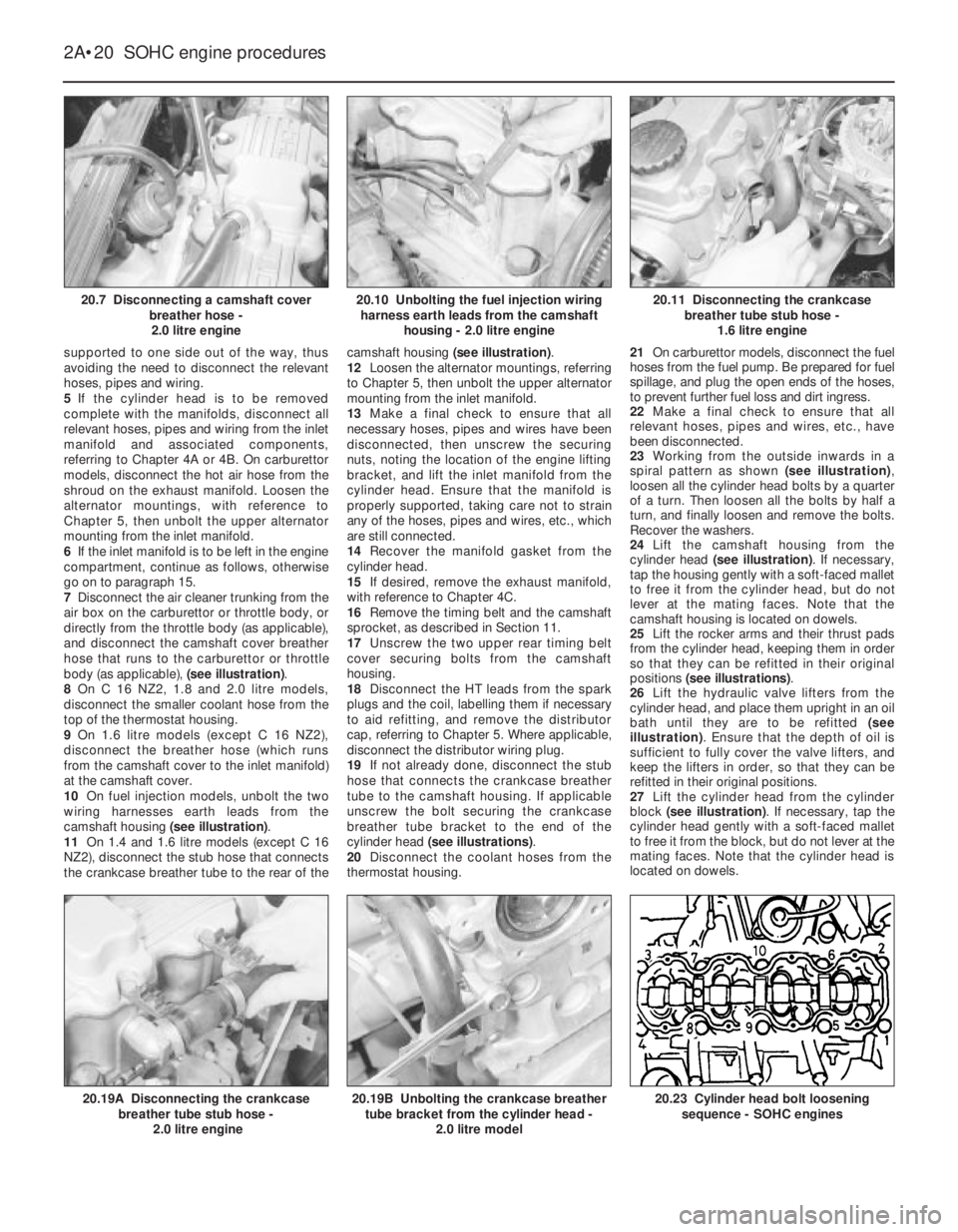
body (as applicable), (see illustration).
8On C 16 NZ2, 1.8 and 2.0 litre models,
disconnect the smaller coolant hose from the
top of the thermostat housing.
9On 1.6 litre models (except C 16 NZ2),
disconnect the breather hose (which runs
from the camshaft cover to the inlet manifold)
at the camshaft cover.
10On fuel injection models, unbolt the two
wiring harnesses earth leads from the
camshaft housing (see illustration).
11On 1.4 and 1.6 litre models (except C 16
NZ2), disconnect the stub hose that connects
the crankcase breather tube to the rear of thecamshaft housing (see illustration).
12Loosen the alternator mountings, referring
to Chapter 5, then unbolt the upper alternator
mounting from the inlet manifold.
13Make a final check to ensure that all
necessary hoses, pipes and wires have been
disconnected, then unscrew the securing
nuts, noting the location of the engine lifting
bracket, and lift the inlet manifold from the
cylinder head. Ensure that the manifold is
properly supported, taking care not to strain
any of the hoses, pipes and wires, etc., which
are still connected.
14Recover the manifold gasket from the
cylinder head.
15If desired, remove the exhaust manifold,
with reference to Chapter 4C.
16Remove the timing belt and the camshaft
sprocket, as described in Section 11.
17Unscrew the two upper rear timing belt
cover securing bolts from the camshaft
housing.
18Disconnect the HT leads from the spark
plugs and the coil, labelling them if necessary
to aid refitting, and remove the distributor
cap, referring to Chapter 5. Where applicable,
disconnect the distributor wiring plug.
19If not already done, disconnect the stub
hose that connects the crankcase breather
tube to the camshaft housing. If applicable
unscrew the bolt securing the crankcase
breather tube bracket to the end of the
cylinder head (see illustrations).
20Disconnect the coolant hoses from the
thermostat housing.21On carburettor models, disconnect the fuel
hoses from the fuel pump. Be prepared for fuel
spillage, and plug the open ends of the hoses,
to prevent further fuel loss and dirt ingress.
22Make a final check to ensure that all
relevant hoses, pipes and wires, etc., have
been disconnected.
23Working from the outside inwards in a
spiral pattern as shown (see illustration),
loosen all the cylinder head bolts by a quarter
of a turn. Then loosen all the bolts by half a
turn, and finally loosen and remove the bolts.
Recover the washers.
24Lift the camshaft housing from the
cylinder head (see illustration). If necessary,
tap the housing gently with a soft-faced mallet
to free it from the cylinder head, but do not
lever at the mating faces. Note that the
camshaft housing is located on dowels.
25Lift the rocker arms and their thrust pads
from the cylinder head, keeping them in order
so that they can be refitted in their original
positions (see illustrations).
26Lift the hydraulic valve lifters from the
cylinder head, and place them upright in an oil
bath until they are to be refitted (see
illustration). Ensure that the depth of oil is
sufficient to fully cover the valve lifters, and
keep the lifters in order, so that they can be
refitted in their original positions.
27Lift the cylinder head from the cylinder
block (see illustration). If necessary, tap the
cylinder head gently with a soft-faced mallet
to free it from the block, but do not lever at the
mating faces. Note that the cylinder head is
located on dowels.
2A•20SOHC engine procedures
20.7 Disconnecting a camshaft cover
breather hose -
2.0 litre engine20.11 Disconnecting the crankcase
breather tube stub hose -
1.6 litre engine
20.23 Cylinder head bolt loosening
sequence - SOHC engines20.19B Unbolting the crankcase breather
tube bracket from the cylinder head -
2.0 litre model20.19A Disconnecting the crankcase
breather tube stub hose -
2.0 litre engine
20.10 Unbolting the fuel injection wiring
harness earth leads from the camshaft
housing - 2.0 litre engine
Page 219 of 525
40Refit the camshaft sprocket and the
timing belt and tension the timing belt as
described in Section 11.
41Where applicable, refit the manifolds to
the cylinder head, with reference to Chapter
4A, 4B or 4C, using new gaskets.
42Reconnect the exhaust downpipe to the
manifold, using a new gasket, referring to
Chapter 4C, if necessary.
43Refit the upper alternator mounting to the
inlet manifold, then adjust the alternator
drivebelt tension, as described in Chapter 5.
44Refill the cooling system, as described in
Chapter 3.
45On completion, check that all relevant
hoses, pipes and wires, etc., have been
reconnected.
46When the engine is started, check for
signs of leaks.
47Once the engine has reached normal
operating temperature, check and if
necessary adjust the idle speed (where
applicable) and the mixture (where
applicable), with reference to Chapter 4A or
4B.
21Cylinder head - removal and
refitting (engine removed)
4
Note: New cylinder head bolts and a new
cylinder head gasket must be used on
refitting, and sealer will be required when
refitting the camshaft housing.
The torque settings stated are only applicable
to latest specification head bolts, available
from Vauxhall. Earlier type or alternative make,
head bolts may require different torques.
Consult your supplier.
Removal
1The cylinder head can be removed
complete with the manifolds, or the manifolds
can be detached from the cylinder head
before removal, with reference Chapter 4A,
4B or 4C.
2Remove the timing belt and the camshaft
sprocket, as described in Section 11.
3Unscrew the two upper rear timing belt
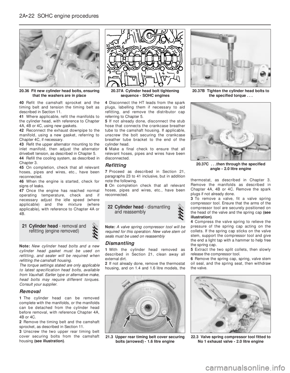
cover securing bolts from the camshaft
housing (see illustration).4Disconnect the HT leads from the spark
plugs, labelling them if necessary to aid
refitting, and remove the distributor cap
referring to Chapter 5.
5If not already done, disconnect the stub
hose that connects the crankcase breather
tube to the camshaft housing. If applicable,
unscrew the bolt securing the crankcase
breather tube bracket to the end of the
cylinder head.
6Make a final check to ensure that all
relevant hoses, pipes and wires have been
disconnected.
Refitting
7Proceed as described in Section 21,
paragraphs 23 to 41 inclusive, but in addition
note the following.
8On completion check that all relevant
hoses, pipes and wires, etc., have been
reconnected.
22Cylinder head -dismantling
and reassembly
4
Note: A valve spring compressor tool will be
required for this operation. New valve stem oil
seals must be used on reassembly
Dismantling
1With the cylinder head removed as
described in Section 21, clean away all
external dirt.
2If not already done, remove the thermostat
housing, and on 1.4 and 1.6 litre models, thethermostat, as described in Chapter 3.
Remove the manifolds as described in
Chapter 4A, 4B or 4C. Remove the spark
plugs if not already done.
3To remove a valve, fit a valve spring
compressor tool. Ensure that the arms of the
compressor tool are securely positioned on
the head of the valve and the spring cap (see
illustration).
4Compress the valve spring to relieve the
pressure of the spring cap acting on the
collets. If the spring cap sticks on the valve
stem, support the compressor tool and give
the end a light tap with a hammer to help free
the spring cap.
5Extract the two split collets, then slowly
release the compressor tool.
6Remove the spring cap, spring, valve stem
oil seal, and the spring seat, then withdraw
the valve.
2A•22SOHC engine procedures
20.36 Fit new cylinder head bolts, ensuring
that the washers are in place20.37B Tighten the cylinder head bolts to
the specified torque . . .
22.3 Valve spring compressor tool fitted to
No 1 exhaust valve - 2.0 litre engine21.3 Upper rear timing belt cover securing
bolts (arrowed) - 1.6 litre engine
20.37C . . .then through the specified
angle - 2.0 litre engine
20.37A Cylinder head bolt tightening
sequence - SOHC engines
Page 253 of 525
MFaulty ignition coil (Chapter 5).
MUneven or low cylinder compressions (Chapter 2A).
MBlocked carburettor jet(s) or internal passages - carburettor
models (Chapter 4A).
MBlocked injector/fuel injection system fault - fuel-injected models
(Chapter 4B).
Engine hesitates on acceleration
MWorn, faulty or incorrectly gapped spark plugs (Chapter 1).
MVacuum leak at the carburettor/throttle body, inlet manifold or
associated hoses (Chapter 4A or 4B).
MBlocked carburettor jet(s) or internal passages - carburettor
models (Chapter 4A).
MBlocked injector/fuel injection system fault - fuel-injected models
(Chapter 4B).
Engine stalls
MVacuum leak at the carburettor/throttle body, inlet manifold or
associated hoses (Chapter 4A or 4B).
MFuel filter choked (Chapter 1).
MFuel pump faulty, or delivery pressure low (Chapter 4A or 4B).
MFuel tank vent blocked, or fuel pipes restricted (Chapter 4A or 4B).
MBlocked carburettor jet(s) or internal passages - carburettor
models (Chapter 4A).
MBlocked injector/fuel injection system fault - fuel-injected models
(Chapter 4B).
Engine lacks power
MTiming belt incorrectly fitted or tensioned (Chapter 2A or 2B).
MFuel filter choked (Chapter 1).
MFuel pump faulty, or delivery pressure low (Chapter 4A or 4B).
MUneven or low cylinder compressions (Chapter 2A).
MWorn, faulty or incorrectly gapped spark plugs (Chapter 1).
MVacuum leak at the carburettor/throttle body, inlet manifold or
associated hoses (Chapter 4A or 4B).
MBlocked carburettor jet(s) or internal passages - carburettor
models (Chapter 4A).
MBlocked injector/fuel injection system fault - fuel-injected models
(Chapter 4B).
MBrakes binding (Chapters 1 and 9).
MClutch slipping (Chapter 6).
Engine backfires
MTiming belt incorrectly fitted or tensioned (Chapter 2A or 2B).
MVacuum leak at the carburettor/throttle body, inlet manifold or
associated hoses (Chapter 4A or 4B).
MBlocked carburettor jet(s) or internal passages - carburettor
models (Chapter 4A).
MBlocked injector/fuel injection system fault - fuel-injected models
(Chapter 4B).
Oil pressure warning light illuminated with engine
running
MLow oil level, or incorrect oil grade (Chapter 1).
MFaulty oil pressure warning light switch (Chapter 12).
MWorn engine bearings and/or oil pump (Chapter 2A).
MHigh engine operating temperature (Chapter 3).
MOil pressure relief valve defective (Chapter 2A).
MOil pick-up strainer clogged (Chapter 2A).
Engine runs-on after switching off
MExcessive carbon build-up in engine (Chapter 2A).
MHigh engine operating temperature (Chapter 3).
MFaulty fuel cut-off solenoid - carburettor models (Chapter 4A).
MFuel injection system fault - fuel-injected models (Chapter 4B).
Engine noises
Pre-ignition (pinking) or knocking during acceleration or
under load
MIgnition timing incorrect/ignition system fault (Chapters 1 and 5).
MIncorrect grade of spark plug (Chapter 1).
MIncorrect grade of fuel (Chapter 1).
MVacuum leak at the carburettor/throttle body, inlet manifold or
associated hoses (Chapter 4A or 4B).
MExcessive carbon build-up in engine (Chapter 2A).
MBlocked carburettor jet(s) or internal passages - carburettor
models (Chapter 4A).
MBlocked injector/fuel injection system fault - fuel-injected models
(Chapter 4B).
Whistling or wheezing noises
MLeaking inlet manifold or carburettor/throttle body gasket
(Chapter 4A or 4B).
MLeaking exhaust manifold gasket or pipe-to-manifold joint
(Chapter 4C).
MLeaking vacuum hose (Chapters 4A, 4B, 4C, 5, 9 and 12).
MBlowing cylinder head gasket (Chapter 2A or 2B).
Tapping or rattling noises
MWorn valve gear or camshaft (Chapter 2A or 2B).
MAncillary component fault (coolant pump, alternator, etc.)
(Chapters 3, 5, etc.).
Knocking or thumping noises
MWorn big-end bearings (regular heavy knocking, perhaps less
under load), (Chapter 2A or 2B).
MWorn main bearings (rumbling and knocking, perhaps worsening
under load), (Chapter 2A or 2B).
MPiston slap (most noticeable when cold), (Chapter 2A).
MAncillary component fault (coolant pump, alternator, etc.)
(Chapters 3, 5, etc.).
REF•14Fault Finding
Engine (continued)
Page 257 of 525
Note:For problems associated with the starting system, refer to the
faults listed under “Engine” earlier in this Section.
Battery will not hold a charge for more than a few
days
MBattery defective internally (Chapter 5).
MBattery terminal connections loose or corroded (Chapter 1).
MAuxiliary drivebelt worn or incorrectly adjusted (Chapter 1).
MAlternator not charging at correct output (Chapter 5).
MAlternator or voltage regulator faulty (Chapter 5).
MShort-circuit causing continual battery drain (Chapters 5 and 12).
Ignition/no-charge warning light remains
illuminated with engine running
MAuxiliary drivebelt broken, worn, or incorrectly adjusted (Chapter 1).
MAlternator brushes worn, sticking, or dirty (Chapter 5).
MAlternator brush springs weak or broken (Chapter 5).
MInternal fault in alternator or voltage regulator (Chapter 5).
MBroken, disconnected, or loose wiring in charging circuit
(Chapter 5).
Ignition/no-charge warning light fails to come on
MWarning light bulb blown (Chapter 12).
MBroken, disconnected, or loose wiring in warning light circuit
(Chapter 12).
MAlternator faulty (Chapter 5).
Lights inoperative
MBulb blown (Chapter 12).
MCorrosion of bulb or bulbholder contacts (Chapter 12).
MBlown fuse (Chapter 12).
MFaulty relay (Chapter 12).
MBroken, loose, or disconnected wiring (Chapter 12).
MFaulty switch (Chapter 12).
Instrument readings inaccurate or erratic
Instrument readings increase with engine speed
MFaulty voltage regulator (Chapter 12).
Fuel or temperature gauges give no reading
MFaulty gauge sender unit (Chapters 3, 4A and 4B).
MWiring open-circuit (Chapter 12).
MFaulty gauge (Chapter 12).
Fuel or temperature gauges give continuous maximum
reading
MFaulty gauge sender unit (Chapters 3, 4A and 4B).
MWiring short-circuit (Chapter 12).
MFaulty gauge (Chapter 12). MIncorrect front wheel alignment (Chapter 10).
MSteering rack or column bent or damaged (Chapter 10).
Excessive play in steering
MWorn steering column intermediate shaft universal joint
(Chapter 10).
MWorn steering track rod end balljoints (Chapters 1 and 10).
MWorn rack-and-pinion steering gear (Chapter 10).
MWorn steering or suspension joints, bushes or components
(Chapters 1 and 10).
Lack of power assistance
MBroken or incorrectly adjusted auxiliary drivebelt (Chapter 1).
MIncorrect power steering fluid level (Chapter 1).
MRestriction in power steering fluid hoses (Chapter 1).
MFaulty power steering pump (Chapter 10).
MFaulty rack-and-pinion steering gear (Chapter 10).
Tyre wear excessive
Tyres worn on inside or outside edges
MTyres under-inflated (wear on both edges), (Chapter 1).
MIncorrect camber or castor angles (wear on one edge only),
(Chapter 10).
MWorn steering or suspension joints, bushes or components
(Chapters 1 and 10).
MExcessively hard cornering.
MAccident damage.
Tyre treads exhibit feathered edges
MIncorrect toe setting (Chapter 10).
Tyres worn in centre of tread
MTyres over-inflated (Chapter 1).
Tyres worn on inside and outside edges
MTyres under-inflated (Chapter 1).
Tyres worn unevenly
MTyres/wheels out of balance (Chapter 1).
MExcessive wheel or tyre run-out (Chapter 1).
MWorn shock absorbers (Chapters 1 and 10).
MFaulty tyre (Chapter 1).
REF•18Fault Finding
Electrical system
Suspension and steering (continued)
Page 259 of 525
REF•20Glossary of Technical Terms
A
ABS (Anti-lock brake system)A system,
usually electronically controlled, that senses
incipient wheel lockup during braking and
relieves hydraulic pressure at wheels that are
about to skid.
Air bag An inflatable bag hidden in the
steering wheel (driver’s side) or the dash or
glovebox (passenger side). In a head-on
collision, the bags inflate, preventing the
driver and front passenger from being thrown
forward into the steering wheel or windscreen.
Air cleanerA metal or plastic housing,
containing a filter element, which removes
dust and dirt from the air being drawn into the
engine.
Air filter elementThe actual filter in an air
cleaner system, usually manufactured from
pleated paper and requiring renewal at regular
intervals.
Allen keyA hexagonal wrench which fits into
a recessed hexagonal hole.
Alligator clipA long-nosed spring-loaded
metal clip with meshing teeth. Used to make
temporary electrical connections.
AlternatorA component in the electrical
system which converts mechanical energy
from a drivebelt into electrical energy to
charge the battery and to operate the starting
system, ignition system and electrical
accessories.
Ampere (amp)A unit of measurement for the
flow of electric current. One amp is the
amount of current produced by one volt
acting through a resistance of one ohm.
Anaerobic sealerA substance used to
prevent bolts and screws from loosening.
Anaerobic means that it does not require
oxygen for activation. The Loctite brand is
widely used.
AntifreezeA substance (usually ethylene
glycol) mixed with water, and added to a
vehicle’s cooling system, to prevent freezing
of the coolant in winter. Antifreeze also
contains chemicals to inhibit corrosion and
the formation of rust and other deposits thatwould tend to clog the radiator and coolant
passages and reduce cooling efficiency.
Anti-seize compoundA coating that
reduces the risk of seizing on fasteners that
are subjected to high temperatures, such as
exhaust manifold bolts and nuts.
AsbestosA natural fibrous mineral with great
heat resistance, commonly used in the
composition of brake friction materials.
Asbestos is a health hazard and the dust
created by brake systems should never be
inhaled or ingested.
AxleA shaft on which a wheel revolves, or
which revolves with a wheel. Also, a solid
beam that connects the two wheels at one
end of the vehicle. An axle which also
transmits power to the wheels is known as a
live axle.
AxleshaftA single rotating shaft, on either
side of the differential, which delivers power
from the final drive assembly to the drive
wheels. Also called a driveshaft or a halfshaft.
BBall bearingAn anti-friction bearing
consisting of a hardened inner and outer race
with hardened steel balls between two races.BearingThe curved surface on a shaft or in a
bore, or the part assembled into either, that
permits relative motion between them with
minimum wear and friction.
Big-end bearingThe bearing in the end of
the connecting rod that’s attached to the
crankshaft.
Bleed nippleA valve on a brake wheel
cylinder, caliper or other hydraulic component
that is opened to purge the hydraulic system
of air. Also called a bleed screw.
Brake bleedingProcedure for removing air
from lines of a hydraulic brake system.
Brake discThe component of a disc brake
that rotates with the wheels.
Brake drumThe component of a drum brake
that rotates with the wheels.
Brake liningsThe friction material which
contacts the brake disc or drum to retard the
vehicle’s speed. The linings are bonded or
riveted to the brake pads or shoes.
Brake padsThe replaceable friction pads
that pinch the brake disc when the brakes are
applied. Brake pads consist of a friction
material bonded or riveted to a rigid backing
plate.
Brake shoeThe crescent-shaped carrier to
which the brake linings are mounted and
which forces the lining against the rotating
drum during braking.
Braking systemsFor more information on
braking systems, consult the Haynes
Automotive Brake Manual.
Breaker barA long socket wrench handle
providing greater leverage.
BulkheadThe insulated partition between
the engine and the passenger compartment.
CCaliperThe non-rotating part of a disc-brake
assembly that straddles the disc and carries
the brake pads. The caliper also contains the
hydraulic components that cause the pads to
pinch the disc when the brakes are applied. A
caliper is also a measuring tool that can be set
to measure inside or outside dimensions of an
object.
Brake bleeding
Bearing
Axle assembly
Anti-seize compound
Alternator (exploded view)
Air filter
Page 260 of 525

Glossary of Technical Terms REF•21
REF
CamshaftA rotating shaft on which a series
of cam lobes operate the valve mechanisms.
The camshaft may be driven by gears, by
sprockets and chain or by sprockets and a
belt.
CanisterA container in an evaporative
emission control system; contains activated
charcoal granules to trap vapours from the
fuel system.
CarburettorA device which mixes fuel with
air in the proper proportions to provide a
desired power output from a spark ignition
internal combustion engine.
CastellatedResembling the parapets along
the top of a castle wall. For example, a
castellated balljoint stud nut.
CastorIn wheel alignment, the backward or
forward tilt of the steering axis. Castor is
positive when the steering axis is inclined
rearward at the top.Catalytic converterA silencer-like device in
the exhaust system which converts certain
pollutants in the exhaust gases into less
harmful substances.
CirclipA ring-shaped clip used to prevent
endwise movement of cylindrical parts and
shafts. An internal circlip is installed in a
groove in a housing; an external circlip fits into
a groove on the outside of a cylindrical piece
such as a shaft.
ClearanceThe amount of space between
two parts. For example, between a piston and
a cylinder, between a bearing and a journal,
etc.
Coil springA spiral of elastic steel found in
various sizes throughout a vehicle, for
example as a springing medium in the
suspension and in the valve train.
CompressionReduction in volume, and
increase in pressure and temperature, of a
gas, caused by squeezing it into a smaller
space.
Compression ratioThe relationship between
cylinder volume when the piston is at top
dead centre and cylinder volume when the
piston is at bottom dead centre.
Constant velocity (CV) jointA type of
universal joint that cancels out vibrations
caused by driving power being transmitted
through an angle.
Core plugA disc or cup-shaped metal device
inserted in a hole in a casting through which
core was removed when the casting was
formed. Also known as a freeze plug or
expansion plug.
CrankcaseThe lower part of the engine
block in which the crankshaft rotates.
CrankshaftThe main rotating member, or
shaft, running the length of the crankcase,
with offset “throws” to which the connecting
rods are attached.Crocodile clipSee Alligator clip
DDiagnostic codeCode numbers obtained by
accessing the diagnostic mode of an engine
management computer. This code can be
used to determine the area in the system
where a malfunction may be located.
Disc brakeA brake design incorporating a
rotating disc onto which brake pads are
squeezed. The resulting friction converts the
energy of a moving vehicle into heat.
Double-overhead cam (DOHC)An engine
that uses two overhead camshafts, usually
one for the intake valves and one for the
exhaust valves.
Drivebelt(s)The belt(s) used to drive
accessories such as the alternator, water
pump, power steering pump, air conditioning
compressor, etc. off the crankshaft pulley.
DriveshaftAny shaft used to transmit
motion. Commonly used when referring to the
axleshafts on a front wheel drive vehicle.
Drum brakeA type of brake using a drum-
shaped metal cylinder attached to the inner
surface of the wheel. When the brake pedal is
pressed, curved brake shoes with friction
linings press against the inside of the drum to
slow or stop the vehicle.
Castellated nut
Catalytic converter
Crankshaft assembly
Carburettor
Canister
Drum brake assembly
Accessory drivebelts
Driveshaft
Page 262 of 525
Glossary of Technical Terms REF•23
JJump startStarting the engine of a vehicle
with a discharged or weak battery by
attaching jump leads from the weak battery to
a charged or helper battery.
LLoad Sensing Proportioning Valve (LSPV)A
brake hydraulic system control valve that
works like a proportioning valve, but also
takes into consideration the amount of weight
carried by the rear axle.
LocknutA nut used to lock an adjustment
nut, or other threaded component, in place.
For example, a locknut is employed to keep
the adjusting nut on the rocker arm in
position.
LockwasherA form of washer designed to
prevent an attaching nut from working loose.
MMacPherson strutA type of front
suspension system devised by Earle
MacPherson at Ford of England. In its original
form, a simple lateral link with the anti-roll bar
creates the lower control arm. A long strut - an
integral coil spring and shock absorber - is
mounted between the body and the steering
knuckle. Many modern so-called MacPherson
strut systems use a conventional lower A-arm
and don’t rely on the anti-roll bar for location.
MultimeterAn electrical test instrument with
the capability to measure voltage, current and
resistance.
NNOxOxides of Nitrogen. A common toxic
pollutant emitted by petrol and diesel engines
at higher temperatures.
OOhmThe unit of electrical resistance. One
volt applied to a resistance of one ohm will
produce a current of one amp.
OhmmeterAn instrument for measuring
electrical resistance.
O-ringA type of sealing ring made of a
special rubber-like material; in use, the O-ring
is compressed into a groove to provide the
sealing action.Overhead cam (ohc) engineAn engine with
the camshaft(s) located on top of the cylinder
head(s).
Overhead valve (ohv) engineAn engine with
the valves located in the cylinder head, but
with the camshaft located in the engine block.
Oxygen sensorA device installed in the
engine exhaust manifold, which senses the
oxygen content in the exhaust and converts
this information into an electric current. Also
called a Lambda sensor.
PPhillips screwA type of screw head having a
cross instead of a slot for a corresponding
type of screwdriver.
PlastigageA thin strip of plastic thread,
available in different sizes, used for measuring
clearances. For example, a strip of Plastigage
is laid across a bearing journal. The parts are
assembled and dismantled; the width of the
crushed strip indicates the clearance between
journal and bearing.
Propeller shaftThe long hollow tube with
universal joints at both ends that carries
power from the transmission to the differential
on front-engined rear wheel drive vehicles.
Proportioning valveA hydraulic control
valve which limits the amount of pressure to
the rear brakes during panic stops to prevent
wheel lock-up.
RRack-and-pinion steeringA steering system
with a pinion gear on the end of the steering
shaft that mates with a rack (think of a geared
wheel opened up and laid flat). When the
steering wheel is turned, the pinion turns,
moving the rack to the left or right. This
movement is transmitted through the track
rods to the steering arms at the wheels.
RadiatorA liquid-to-air heat transfer device
designed to reduce the temperature of the
coolant in an internal combustion engine
cooling system.
RefrigerantAny substance used as a heat
transfer agent in an air-conditioning system.
R-12 has been the principle refrigerant for
many years; recently, however, manufacturers
have begun using R-134a, a non-CFC
substance that is considered less harmful tothe ozone in the upper atmosphere.
Rocker armA lever arm that rocks on a shaft
or pivots on a stud. In an overhead valve
engine, the rocker arm converts the upward
movement of the pushrod into a downward
movement to open a valve.
RotorIn a distributor, the rotating device
inside the cap that connects the centre
electrode and the outer terminals as it turns,
distributing the high voltage from the coil
secondary winding to the proper spark plug.
Also, that part of an alternator which rotates
inside the stator. Also, the rotating assembly
of a turbocharger, including the compressor
wheel, shaft and turbine wheel.
RunoutThe amount of wobble (in-and-out
movement) of a gear or wheel as it’s rotated.
The amount a shaft rotates “out-of-true.” The
out-of-round condition of a rotating part.
SSealantA liquid or paste used to prevent
leakage at a joint. Sometimes used in
conjunction with a gasket.
Sealed beam lampAn older headlight design
which integrates the reflector, lens and
filaments into a hermetically-sealed one-piece
unit. When a filament burns out or the lens
cracks, the entire unit is simply replaced.
Serpentine drivebeltA single, long, wide
accessory drivebelt that’s used on some
newer vehicles to drive all the accessories,
instead of a series of smaller, shorter belts.
Serpentine drivebelts are usually tensioned by
an automatic tensioner.
ShimThin spacer, commonly used to adjust
the clearance or relative positions between
two parts. For example, shims inserted into or
under bucket tappets control valve
clearances. Clearance is adjusted by
changing the thickness of the shim.
Slide hammerA special puller that screws
into or hooks onto a component such as a
shaft or bearing; a heavy sliding handle on the
shaft bottoms against the end of the shaft to
knock the component free.
SprocketA tooth or projection on the
periphery of a wheel, shaped to engage with a
chain or drivebelt. Commonly used to refer to
the sprocket wheel itself.
Starter inhibitor switchOn vehicles with an
O-ring
Serpentine drivebelt
Plastigage
REF