1988 OPEL CALIBRA relay
[x] Cancel search: relayPage 159 of 525
9Fuel filter (‘Out-of-tank’ fuel
pump models) - removal and
refitting
3
Note: Refer to Section 2 before proceeding
Removal
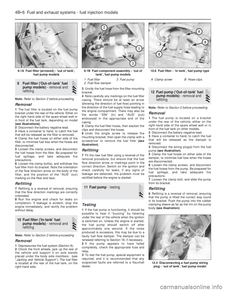
1The fuel filter is located on the fuel pump
bracket under the rear of the vehicle. Either on
the right-hand side of the spare wheel well or
in front of the fuel tank, depending on model
(see illustrations).
2Disconnect the battery negative lead.
3Have a container to hand, to catch the fuel
that will be released as the filter is removed.
4Clamp the fuel hoses on either side of the
filter, to minimise fuel loss when the hoses are
disconnected.
5Loosen the clamp screws, and disconnect
the fuel hoses from the filter. Be prepared for
fuel spillage, and take adequate fire
precautions.
6Loosen the clamp bolt(s), and withdraw the
fuel filter from its bracket. Note the orientation
of the flow direction arrow on the body of the
filter, and the position of the “AUS” (out)
marking on the filter end face.
Refitting
7Refitting is a reversal of removal, ensuring
that the flow direction markings are correctly
orientated.
8Run the engine and check for leaks on
completion. If leakage is evident, stop the
engine immediately, and rectify the problem
without delay.
10Fuel filter (‘In-tank’ fuel
pump models) - removal and
refitting
3
Note: Refer to Section 2 before proceeding
Removal
1Depressurise the fuel system (Section 8).
2Chock the front wheels, jack up the rear of
the vehicle and support it on axle stands
placed under the body side members. (see
“Jacking and Vehicle Support”). The fuel filter
is located at the rear of the fuel tank, on the
right-hand side.3Unclip the fuel hose from the filter mounting
bracket.
4Note carefully any markings on the fuel filter
casing. There should be at least an arrow
(showing the direction of fuel flow) pointing in
the direction of the fuel supply hose leading to
the engine compartment. There may also be
the words “EIN” (in) and “AUS” (out)
embossed in the appropriate end of the
casing.
5Clamp the fuel filter hoses, then slacken the
clips and disconnect the hoses.
6Undo the single screw to release the
mounting bracket, then open the clamp with a
screwdriver to remove the fuel filter (see
illustration).
Refitting
7Fit the new fuel filter using a reversal of the
removal procedure, but ensure that the fuel
flow direction arrow or markings point in the
correct direction. Switch on the ignition and
check carefully for leaks; if any signs of
leakage are detected, the problem must be
rectified before the engine is started.
11Fuel pump - testing
2
Testing
1If the fuel pump is functioning, it should be
possible to hear it “buzzing” by listening
under the rear of the vehicle when the ignition
is switched on. Unless the engine is started,
the fuel pump should switch off after
approximately one second. If the noise
produced is excessive, this may be due to a
faulty fuel flow damper. The damper can be
renewed referring to Section 18, if necessary.
2If the pump appears to have failed
completely, check the appropriate fuse and
relay.
3To test the fuel pump, special equipment is
required, and it is recommended that any
suspected faults are referred to a Vauxhall
dealer.
12Fuel pump (‘Out-of-tank’ fuel
pump models) - removal and
refitting
3
Note: Refer to Section 2 before proceeding
Removal
1The fuel pump is located on a bracket
under the rear of the vehicle, either on the
right-hand side of the spare wheel well or in
front of the fuel tank on other models.
2Disconnect the battery negative lead.
3Have a container to hand, to catch the fuel
that will be released as the damper is
removed.
4Disconnect the wiring plug(s) from the fuel
pump (see illustration).
5Clamp the fuel hoses on either side of the
damper, to minimise fuel loss when the hoses
are disconnected.
6Loosen the clamp screws, and disconnect
the fuel hoses from the pump. Be prepared for
fuel spillage, and take adequate fire
precautions.
7Loosen the clamp bolt, and slide the pump
from its bracket.
Refitting
8Refitting is a reversal of removal, ensuring
that the pump is fitted the correct way round
in its bracket. Push the pump into the rubber
clamping sleeve as far as the rim on the pump
body (see illustration).
4B•6Fuel and exhaust systems - fuel injection models
9.1A Fuel filter (arrowed) - ‘out of tank’,
fuel pump models10.6 Fuel filter - ‘in tank’, fuel pump type
A Clamp screwB Hose clips
12.4 Disconnecting a fuel pump wiring
plug - ‘out of tank’, fuel pump model
9.1B Fuel component assembly - ‘out of
tank’, fuel pump models
1 Fuel filter
2 Fuel flow damper3 Fuel pump
Page 160 of 525
4B
9Run the engine and check for leaks on
completion. If leakage is evident, stop the
engine immediately, and rectify the problem
without delay.
13Fuel pump (‘In-tank’ fuel
pump models) - removal and
refitting
3
Removal
1Depressurise the fuel system (Section 8),
then remove and refit the fuel filler cap to
ensure that the pressure is equalised inside
and outside the tank.
2Disconnect the battery negative terminal.
3Fold forwards the rear seat cushion. Peel
back the floor covering beneath it, then
remove the cover plug from the vehicle floor
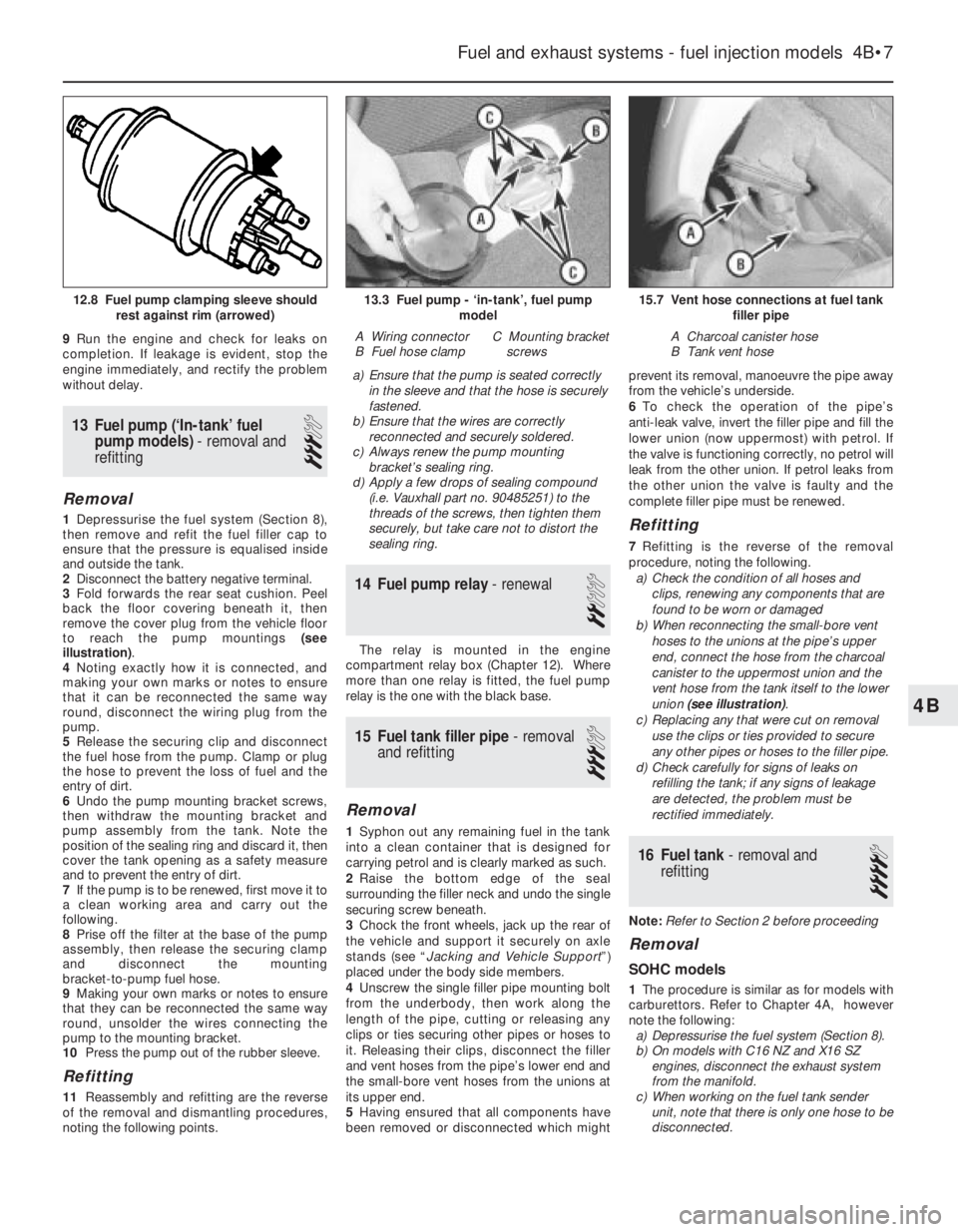
to reach the pump mountings (see
illustration).
4Noting exactly how it is connected, and
making your own marks or notes to ensure
that it can be reconnected the same way
round, disconnect the wiring plug from the
pump.
5Release the securing clip and disconnect
the fuel hose from the pump. Clamp or plug
the hose to prevent the loss of fuel and the
entry of dirt.
6Undo the pump mounting bracket screws,
then withdraw the mounting bracket and
pump assembly from the tank. Note the
position of the sealing ring and discard it, then
cover the tank opening as a safety measure
and to prevent the entry of dirt.
7If the pump is to be renewed, first move it to
a clean working area and carry out the
following.
8Prise off the filter at the base of the pump
assembly, then release the securing clamp
and disconnect the mounting
bracket-to-pump fuel hose.
9Making your own marks or notes to ensure
that they can be reconnected the same way
round, unsolder the wires connecting the
pump to the mounting bracket.
10Press the pump out of the rubber sleeve.
Refitting
11Reassembly and refitting are the reverse
of the removal and dismantling procedures,
noting the following points.a)Ensure that the pump is seated correctly
in the sleeve and that the hose is securely
fastened.
b)Ensure that the wires are correctly
reconnected and securely soldered.
c)Always renew the pump mounting
bracket’s sealing ring.
d)Apply a few drops of sealing compound
(i.e. Vauxhall part no. 90485251) to the
threads of the screws, then tighten them
securely, but take care not to distort the
sealing ring.
14Fuel pump relay - renewal
2
The relay is mounted in the engine
compartment relay box (Chapter 12). Where
more than one relay is fitted, the fuel pump
relay is the one with the black base.
15Fuel tank filler pipe - removal
and refitting
3
Removal
1Syphon out any remaining fuel in the tank
into a clean container that is designed for
carrying petrol and is clearly marked as such.
2Raise the bottom edge of the seal
surrounding the filler neck and undo the single
securing screw beneath.
3Chock the front wheels, jack up the rear of
the vehicle and support it securely on axle
stands (see “Jacking and Vehicle Support”)
placed under the body side members.
4Unscrew the single filler pipe mounting bolt
from the underbody, then work along the
length of the pipe, cutting or releasing any
clips or ties securing other pipes or hoses to
it. Releasing their clips, disconnect the filler
and vent hoses from the pipe’s lower end and
the small-bore vent hoses from the unions at
its upper end.
5Having ensured that all components have
been removed or disconnected which mightprevent its removal, manoeuvre the pipe away
from the vehicle’s underside.
6To check the operation of the pipe’s
anti-leak valve, invert the filler pipe and fill the
lower union (now uppermost) with petrol. If
the valve is functioning correctly, no petrol will
leak from the other union. If petrol leaks from
the other union the valve is faulty and the
complete filler pipe must be renewed.
Refitting
7Refitting is the reverse of the removal
procedure, noting the following.
a)Check the condition of all hoses and
clips, renewing any components that are
found to be worn or damaged
b)When reconnecting the small-bore vent
hoses to the unions at the pipe’s upper
end, connect the hose from the charcoal
canister to the uppermost union and the
vent hose from the tank itself to the lower
union (see illustration).
c)Replacing any that were cut on removal
use the clips or ties provided to secure
any other pipes or hoses to the filler pipe.
d)Check carefully for signs of leaks on
refilling the tank; if any signs of leakage
are detected, the problem must be
rectified immediately.
16Fuel tank - removal and
refitting
4
Note: Refer to Section 2 before proceeding
Removal
SOHC models
1The procedure is similar as for models with
carburettors. Refer to Chapter 4A, however
note the following:
a)Depressurise the fuel system (Section 8).
b)On models with C16 NZ and X16 SZ
engines, disconnect the exhaust system
from the manifold.
c)When working on the fuel tank sender
unit, note that there is only one hose to be
disconnected.
Fuel and exhaust systems - fuel injection models 4B•7
15.7 Vent hose connections at fuel tank
filler pipe
A Charcoal canister hose
B Tank vent hose
13.3 Fuel pump - ‘in-tank’, fuel pump
model
A Wiring connector
B Fuel hose clampC Mounting bracket
screws
12.8 Fuel pump clamping sleeve should
rest against rim (arrowed)
Page 177 of 525
1•6Maintenance - component location
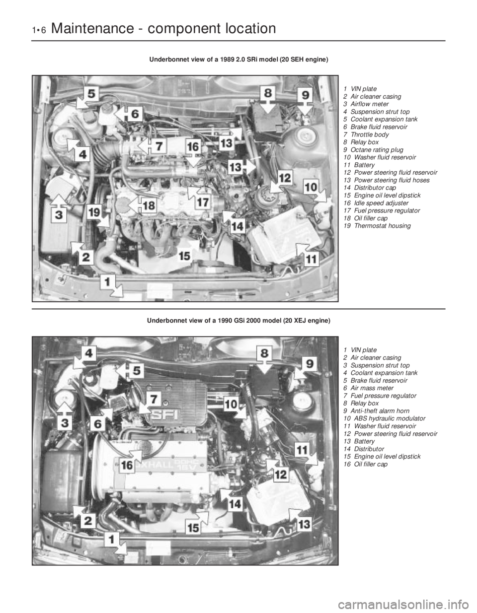
Underbonnet view of a 1989 2.0 SRi model (20 SEH engine)
1 VIN plate
2 Air cleaner casing
3 Airflow meter
4 Suspension strut top
5 Coolant expansion tank
6 Brake fluid reservoir
7 Throttle body
8 Relay box
9 Octane rating plug
10 Washer fluid reservoir
11 Battery
12 Power steering fluid reservoir
13 Power steering fluid hoses
14 Distributor cap
15 Engine oil level dipstick
16 Idle speed adjuster
17 Fuel pressure regulator
18 Oil filler cap
19 Thermostat housing
Underbonnet view of a 1990 GSi 2000 model (20 XEJ engine)
1 VIN plate
2 Air cleaner casing
3 Suspension strut top
4 Coolant expansion tank
5 Brake fluid reservoir
6 Air mass meter
7 Fuel pressure regulator
8 Relay box
9 Anti-theft alarm horn
10 ABS hydraulic modulator
11 Washer fluid reservoir
12 Power steering fluid reservoir
13 Battery
14 Distributor
15 Engine oil level dipstick
16 Oil filler cap
Page 257 of 525
Note:For problems associated with the starting system, refer to the
faults listed under “Engine” earlier in this Section.
Battery will not hold a charge for more than a few
days
MBattery defective internally (Chapter 5).
MBattery terminal connections loose or corroded (Chapter 1).
MAuxiliary drivebelt worn or incorrectly adjusted (Chapter 1).
MAlternator not charging at correct output (Chapter 5).
MAlternator or voltage regulator faulty (Chapter 5).
MShort-circuit causing continual battery drain (Chapters 5 and 12).
Ignition/no-charge warning light remains
illuminated with engine running
MAuxiliary drivebelt broken, worn, or incorrectly adjusted (Chapter 1).
MAlternator brushes worn, sticking, or dirty (Chapter 5).
MAlternator brush springs weak or broken (Chapter 5).
MInternal fault in alternator or voltage regulator (Chapter 5).
MBroken, disconnected, or loose wiring in charging circuit
(Chapter 5).
Ignition/no-charge warning light fails to come on
MWarning light bulb blown (Chapter 12).
MBroken, disconnected, or loose wiring in warning light circuit
(Chapter 12).
MAlternator faulty (Chapter 5).
Lights inoperative
MBulb blown (Chapter 12).
MCorrosion of bulb or bulbholder contacts (Chapter 12).
MBlown fuse (Chapter 12).
MFaulty relay (Chapter 12).
MBroken, loose, or disconnected wiring (Chapter 12).
MFaulty switch (Chapter 12).
Instrument readings inaccurate or erratic
Instrument readings increase with engine speed
MFaulty voltage regulator (Chapter 12).
Fuel or temperature gauges give no reading
MFaulty gauge sender unit (Chapters 3, 4A and 4B).
MWiring open-circuit (Chapter 12).
MFaulty gauge (Chapter 12).
Fuel or temperature gauges give continuous maximum
reading
MFaulty gauge sender unit (Chapters 3, 4A and 4B).
MWiring short-circuit (Chapter 12).
MFaulty gauge (Chapter 12). MIncorrect front wheel alignment (Chapter 10).
MSteering rack or column bent or damaged (Chapter 10).
Excessive play in steering
MWorn steering column intermediate shaft universal joint
(Chapter 10).
MWorn steering track rod end balljoints (Chapters 1 and 10).
MWorn rack-and-pinion steering gear (Chapter 10).
MWorn steering or suspension joints, bushes or components
(Chapters 1 and 10).
Lack of power assistance
MBroken or incorrectly adjusted auxiliary drivebelt (Chapter 1).
MIncorrect power steering fluid level (Chapter 1).
MRestriction in power steering fluid hoses (Chapter 1).
MFaulty power steering pump (Chapter 10).
MFaulty rack-and-pinion steering gear (Chapter 10).
Tyre wear excessive
Tyres worn on inside or outside edges
MTyres under-inflated (wear on both edges), (Chapter 1).
MIncorrect camber or castor angles (wear on one edge only),
(Chapter 10).
MWorn steering or suspension joints, bushes or components
(Chapters 1 and 10).
MExcessively hard cornering.
MAccident damage.
Tyre treads exhibit feathered edges
MIncorrect toe setting (Chapter 10).
Tyres worn in centre of tread
MTyres over-inflated (Chapter 1).
Tyres worn on inside and outside edges
MTyres under-inflated (Chapter 1).
Tyres worn unevenly
MTyres/wheels out of balance (Chapter 1).
MExcessive wheel or tyre run-out (Chapter 1).
MWorn shock absorbers (Chapters 1 and 10).
MFaulty tyre (Chapter 1).
REF•18Fault Finding
Electrical system
Suspension and steering (continued)
Page 258 of 525
Horn inoperative, or unsatisfactory in operation
Horn operates all the time
MHorn push either earthed or stuck down (Chapter 12).
MHorn cable-to-horn push earthed (Chapter 12).
Horn fails to operate
MBlown fuse (Chapter 12).
MCable or cable connections loose, broken or disconnected
(Chapter 12).
MFaulty horn (Chapter 12).
Horn emits intermittent or unsatisfactory sound
MCable connections loose (Chapter 12).
MHorn mountings loose (Chapter 12).
MFaulty horn (Chapter 12).
Windscreen/tailgate wipers inoperative, or unsat-
isfactory in operation
Wipers fail to operate, or operate very slowly
MWiper blades stuck to screen, or linkage seized or binding
(Chapters 1 and 12).
MBlown fuse (Chapter 12).
MCable or cable connections loose, broken or disconnected
(Chapter 12).
MFaulty relay (Chapter 12).
MFaulty wiper motor (Chapter 12).
Wiper blades sweep over too large or too small an area of
the glass
MWiper arms incorrectly positioned on spindles (Chapter 1).
MExcessive wear of wiper linkage (Chapter 12).
MWiper motor or linkage mountings loose or insecure (Chapter 12).
Wiper blades fail to clean the glass effectively
MWiper blade rubbers worn or perished (Chapter 1).
MWiper arm tension springs broken, or arm pivots seized
(Chapter 12).
MInsufficient windscreen washer additive to adequately remove
road film (Chapter 1).
Windscreen/tailgate washers inoperative, or
unsatisfactory in operation
One or more washer jets inoperative
MBlocked washer jet (Chapter 1).
MDisconnected, kinked or restricted fluid hose (Chapter 12).
MInsufficient fluid in washer reservoir (Chapter 1).
Washer pump fails to operate
MBroken or disconnected wiring or connections (Chapter 12).
MBlown fuse (Chapter 12).
MFaulty washer switch (Chapter 12).
MFaulty washer pump (Chapter 12).
Washer pump runs for some time before fluid is emitted
from jets
MFaulty one-way valve in fluid supply hose (Chapter 12).
Electric windows inoperative, or unsatisfactory in
operation
Window glass will only move in one direction
MFaulty switch (Chapter 12).
Window glass slow to move
MRegulator seized or damaged, or in need of lubrication
(Chapter 11).
MDoor internal components or trim fouling regulator (Chapter 11).
MFaulty motor (Chapter 12).
Window glass fails to move
MBlown fuse (Chapter 12).
MFaulty relay (Chapter 12).
MBroken or disconnected wiring or connections (Chapter 12).
MFaulty motor (Chapter 12).
Central locking system inoperative, or unsatis-
factory in operation
Complete system failure
MBlown fuse (Chapter 12).
MFaulty relay (Chapter 12).
MBroken or disconnected wiring or connections (Chapter 12).
MFaulty control module (Chapter 12).
Latch locks but will not unlock, or unlocks but will not lock
MFaulty master switch (Chapter 12).
MBroken or disconnected latch operating rods or levers
(Chapter 11).
MFaulty relay (Chapter 12).
MFaulty control module (Chapter 12).
One solenoid/motor fails to operate
MBroken or disconnected wiring or connections (Chapter 12).
MFaulty solenoid/motor (Chapter 12).
MBroken, binding or disconnected latch operating rods or levers
(Chapter 11).
MFault in door latch (Chapter 11).
Fault Finding REF•19
REF
Electrical system (continued)
Page 266 of 525
Pierburg 2E3 carburettor- 4A•5
Piston rings- 2A•30
Piston/connecting rod- 2A•29
Plastic components- 11•3
Potentiometer- 4B•12, 4B•16
Power steering fluid - 0•14, 0•17, 1•2, 1•12
Power steering pump- 10•22
Power steering system bleeding- 10•22
Punctures- 0•8
RRadiator- 3•3
Radiator cooling fan- 3•5
Radiator grille- 11•12
Radio/cassette anti theft system- REF•5
Radio/cassette player- 12•18
Rear hub- 10•10, 10•15
Rear lamps- 12•11
Rear suspension assembly- 10•15
Relays- 12•3
Release bearing (clutch)- 6•6
Repair procedures- REF •4
Respraying- 11•2
Reversing lamp switch- 7A•6
Road test- 1•13
Roll bars- 10•8, 10•13, 10•17
Routine maintenance - 1•1 et seq
SSafety first!- 0•5
Scratches- 11•2
Seat belts- 11•21
Seats- 11•20, 11•22
Seats heated- 12•6
Selector cable (automatics)- 7B•4
Selector lever- 7B•4
Sender unit fuel level- 4A•4, 4B•8
Sender units (temperature gauge)- 3•6
Servicing - see Routine maintenance
Servo unit (braking system)- 9•15
Shock absorber- 10•11
Shoes (brake)- 9•6
Short-circuit finding- 12•2
Spark plugs- 1•3, 1•14, 1•16
Speakers- 12•17
Speedometer cable- 12•18
Speedometer drive- 7A•6
Starter inhibitor switch- 7B•3
Starter motor- 5•8
Starting problems- 0•6
Steering wheel alignment- 10•1, 10•24
Steering- 10•1 et seq
camber - 10•1 10•24
castor - 10•1, 10•24
column - 10•18
damper - 10•21
fault diagnosis - REF•12, REF•17gear - 10•21
power steering system bleeding - 10•22
power steering fluid - 0•17, 1•2
power steering pump - 10•22
shaft rubber coupling - 10•18
tie-rod end - 10•23
toe setting - 10•1, 10•24
wheel - 10•17
wheel bearing - 10•4, 10•9, 10•14
wheel with airbag - 12•20
Stub axle- 10•13
Subframe- 10•5
Sump- 2A•27, 2B•9
Sunroof- 11•13
Sunroof motor- 12•18
Sunroof switch- 12•5
Suspension- 10•1 et seq
anti-roll bars - 10•8, 10•13, 10•17
assembly (rear) - 10•15
coil spring (rear) - 10•12, 10•15
fault diagnosis - REF•12, REF•17
level control system - 10•14
lower arm (front) - 10•7
rear hub - 10•10, 10•15
shock absorber - 10•11
strut (front) - 10•6
stub axle - 10•13
sub frame - 10•5
trailing arms - 10•12, 10•16
wheel bearing - 10•4, 10•9, 10•14
Suspension/steering checks- 1•10
Switches:
brake lamp - 12•5
cooling fan - 3•6
courtesy lamp - 12•5
electric door mirror - 12•5
handbrake warning lamp - 12•5
hazard warning - 12•4
heater blower motor - 12•4
ignition - 12•3
indicator - 12•4
kickdown - 7B•3
lights - 12•4
luggage compartment - 12•5
oil pressure warning lamp - 12•5
push button - 12•4
reversing lamp - 7A•6
starter inhibitor - 7B•3
sunroof - 12•5
TTailgate- 11•5
Temperature gauge sender- 3•6
Temperature sensor (automatics)- 7B•5
Thermostat- 3•4
Throttle cable- 4A•5, 4B•9
Throttle pedal- 4A•5Tie-rod end- 10•23
Timing- 5•2, 5•13
Timing belt- 1•16, 2A•13, 2B•3, 2B•6
Toe setting- 10•1, 10•24
Tools and working facilities- REF•4, REF•6,
REF•7
Towing- 0•9
Trim panel (door)- 11•6
Tyre checks- 0•16, 0•17
Tyre pressures- 0•17
UUnderbody- 11•1
Underbody views- 1•7
Underbonnet views- 0•10, 1•5
Upholstery and carpets- 11•2
VVacuum servo unit (braking system)- 9•15
Valve lifters- 2A•24, 2B•9
Valves- 2A•5, 2B•2
Vehicle identification numbers- REF•3
Ventilation system- 3•1 et seq
Vents- 3•8
WWasher fluid- 0•13, 1•2
Washers- 12•13, 12•15
Water pump- 3•4
Weekly checks- 0•10et seq
Wheelalignment- 10•1, 10•24
Wheel arch liners- 11•12
Wheel bearing- 10•4, 10•9, 10•14
Wheel changing- 0•8
Wheel cylinder- 9•11
Window glass- 11•9
Window regulator- 11•10
Windscreen- 11•9, 11•12
Wiper blades- 0•15, 12•13
Wiper motors- 12•14
Wiring diagrams- 12•22 et seq
Index REF•27
REF