1988 OPEL CALIBRA oil level
[x] Cancel search: oil levelPage 206 of 525
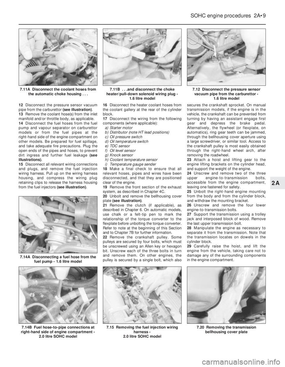
12Disconnect the pressure sensor vacuum
pipe from the carburettor (see illustration).
13Remove the coolant hose(s) from the inlet
manifold and/or throttle body, as applicable.
14Disconnect the fuel hoses from the fuel
pump and vapour separator on carburettor
models or from the fuel pipes at the
right-hand side of the engine compartment on
other models. Be prepared for fuel spillage,
and take adequate fire precautions. Plug the
open ends of the pipes and hoses, to prevent
dirt ingress and further fuel leakage (see
illustrations).
15Disconnect all relevant wiring connections
and plugs, and remove the fuel injection
wiring harness. Pull up on the wiring harness
housing, and compress the wiring plug
retaining clips to release the harness housing
from the fuel injectors (see illustration).16Disconnect the heater coolant hoses from
the coolant gallery at the rear of the cylinder
block.
17Disconnect the wiring from the following
components (where applicable):
a)Starter motor
b)Distributor (note HT lead positions)
c)Oil pressure switch
d)Oil temperature switch
e)TDC sensor
f)Oil level sensor
g)Knock sensor
h)Coolant temperature sensor
i)Temperature gauge sender
18Make a final check to ensure that all
relevant hoses, pipes and wires have been
disconnected, and that they are positioned
clear of the engine.
19Remove the front section of the exhaust
system, as described in Chapter 4C.
20Unbolt and remove the bellhousing cover
plate (see illustration).
21Remove the clutch (if applicable), as
described in Chapter 6. On automatic models,
use chalk or a felt-tip pen to mark the
relationship of the torque converter to the
flexplate before unbolting the torque converter.
Refer to note at the beginning of this Section
and to Chapter 7B for further information.
22Remove the crankshaft pulley. Some
pulleys are secured by four bolts, which must
be unscrewed using an Allen key or hexagon
bit. Unscrew each of the three bolts in turn
and remove them. On other engines, the
pulley is secured by a single bolt, which alsosecures the crankshaft sprocket. On manual
transmission models, if the engine is in the
vehicle, the crankshaft can be prevented from
turning by having an assistant engage first
gear and depress the brake pedal.
Alternatively, the flywheel (or flexplate, on
automatics), ring gear teeth can be jammed,
through the bellhousing cover aperture using
a large screwdriver, or similar tool. Access to
the crankshaft pulley is most easily obtained
through the right-hand wheel arch, after
removing the roadwheel.
23Attach a hoist and lifting gear to the
engine lifting brackets on the cylinder head,
and support the weight of the engine.
24Unscrew and remove two of the three
upper engine-to-transmission bolts,
accessible from the engine compartment,
leaving one fastened for safety.
25Unbolt the right-hand engine mounting
from the body and from the cylinder block,
and withdraw the mounting bracket.
26Unscrew and remove the four lower
engine-to-transmission bolts.
27Support the transmission using a trolley
jack and interposed block of wood. Remove
the last upper transmission bolt.
28Manipulate the engine as necessary to
separate it from the transmission. Note that
the transmission locates on dowels in the
cylinder block.
29Carefully raise the hoist, and lift the
engine from the vehicle, taking care not to
damage any of the surrounding components
in the engine compartment.
SOHC engine procedures 2A•9
7.12 Disconnect the pressure sensor
vacuum pipe from the carburettor -
1.6 litre model
7.20 Removing the transmission
bellhousing cover plate7.15 Removing the fuel injection wiring
harness -
2.0 litre SOHC model7.14B Fuel hose-to-pipe connections at
right-hand side of engine compartment -
2.0 litre SOHC model
7.14A Disconnecting a fuel hose from the
fuel pump - 1.6 litre model
7.11B . . .and disconnect the choke
heater/pull-down solenoid wiring plug -
1.6 litre model7.11A Disconnect the coolant hoses from
the automatic choke housing . . .
2A
Page 208 of 525
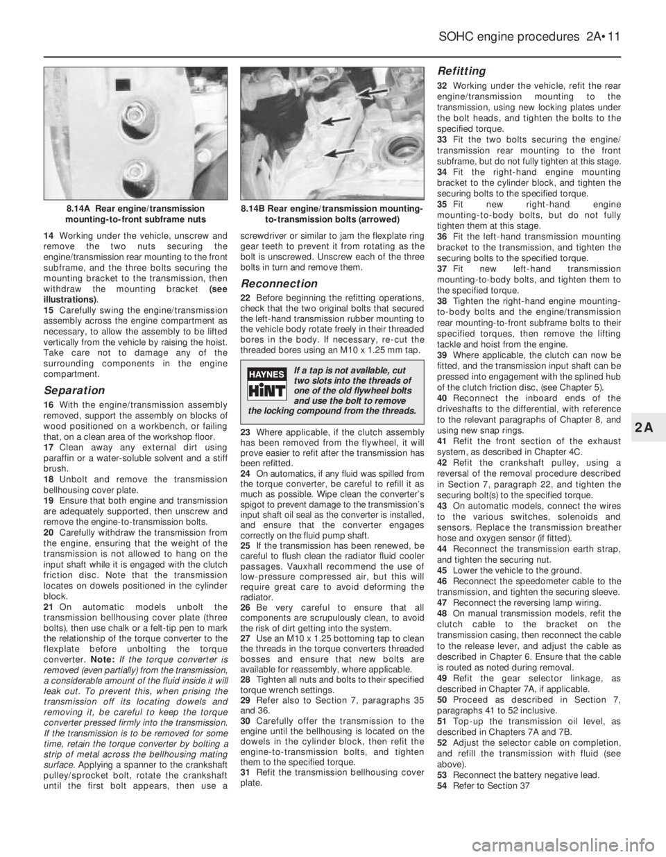
14Working under the vehicle, unscrew and
remove the two nuts securing the
engine/transmission rear mounting to the front
subframe, and the three bolts securing the
mounting bracket to the transmission, then
withdraw the mounting bracket (see
illustrations).
15Carefully swing the engine/transmission
assembly across the engine compartment as
necessary, to allow the assembly to be lifted
vertically from the vehicle by raising the hoist.
Take care not to damage any of the
surrounding components in the engine
compartment.
Separation
16With the engine/transmission assembly
removed, support the assembly on blocks of
wood positioned on a workbench, or failing
that, on a clean area of the workshop floor.
17Clean away any external dirt using
paraffin or a water-soluble solvent and a stiff
brush.
18Unbolt and remove the transmission
bellhousing cover plate.
19Ensure that both engine and transmission
are adequately supported, then unscrew and
remove the engine-to-transmission bolts.
20Carefully withdraw the transmission from
the engine, ensuring that the weight of the
transmission is not allowed to hang on the
input shaft while it is engaged with the clutch
friction disc. Note that the transmission
locates on dowels positioned in the cylinder
block.
21On automatic models unbolt the
transmission bellhousing cover plate (three
bolts), then use chalk or a felt-tip pen to mark
the relationship of the torque converter to the
flexplate before unbolting the torque
converter. Note:If the torque converter is
removed (even partially) from the transmission,
a considerable amount of the fluid inside it will
leak out. To prevent this, when prising the
transmission off its locating dowels and
removing it, be careful to keep the torque
converter pressed firmly into the transmission.
If the transmission is to be removed for some
time, retain the torque converter by bolting a
strip of metal across the bellhousing mating
surface. Applying a spanner to the crankshaft
pulley/sprocket bolt, rotate the crankshaft
until the first bolt appears, then use ascrewdriver or similar to jam the flexplate ring
gear teeth to prevent it from rotating as the
bolt is unscrewed. Unscrew each of the three
bolts in turn and remove them.
Reconnection
22Before beginning the refitting operations,
check that the two original bolts that secured
the left-hand transmission rubber mounting to
the vehicle body rotate freely in their threaded
bores in the body. If necessary, re-cut the
threaded bores using an M10 x 1.25 mm tap.
23Where applicable, if the clutch assembly
has been removed from the flywheel, it will
prove easier to refit after the transmission has
been refitted.
24On automatics, if any fluid was spilled from
the torque converter, be careful to refill it as
much as possible. Wipe clean the converter’s
spigot to prevent damage to the transmission’s
input shaft oil seal as the converter is installed,
and ensure that the converter engages
correctly on the fluid pump shaft.
25If the transmission has been renewed, be
careful to flush clean the radiator fluid cooler
passages. Vauxhall recommend the use of
low-pressure compressed air, but this will
require great care to avoid deforming the
radiator.
26Be very careful to ensure that all
components are scrupulously clean, to avoid
the risk of dirt getting into the system.
27Use an M10 x 1.25 bottoming tap to clean
the threads in the torque converters threaded
bosses and ensure that new bolts are
available for reassembly, where applicable.
28Tighten all nuts and bolts to their specified
torque wrench settings.
29Refer also to Section 7, paragraphs 35
and 36.
30Carefully offer the transmission to the
engine until the bellhousing is located on the
dowels in the cylinder block, then refit the
engine-to-transmission bolts, and tighten
them to the specified torque.
31Refit the transmission bellhousing cover
plate.
Refitting
32Working under the vehicle, refit the rear
engine/transmission mounting to the
transmission, using new locking plates under
the bolt heads, and tighten the bolts to the
specified torque.
33Fit the two bolts securing the engine/
transmission rear mounting to the front
subframe, but do not fully tighten at this stage.
34Fit the right-hand engine mounting
bracket to the cylinder block, and tighten the
securing bolts to the specified torque.
35Fit new right-hand engine
mounting-to-body bolts, but do not fully
tighten them at this stage.
36Fit the left-hand transmission mounting
bracket to the transmission, and tighten the
securing bolts to the specified torque.
37Fit new left-hand transmission
mounting-to-body bolts, and tighten them to
the specified torque.
38Tighten the right-hand engine mounting-
to-body bolts and the engine/transmission
rear mounting-to-front subframe bolts to their
specified torques, then remove the lifting
tackle and hoist from the engine.
39Where applicable, the clutch can now be
fitted, and the transmission input shaft can be
pressed into engagement with the splined hub
of the clutch friction disc, (see Chapter 5).
40Reconnect the inboard ends of the
driveshafts to the differential, with reference
to the relevant paragraphs of Chapter 8, and
using new snap rings.
41Refit the front section of the exhaust
system, as described in Chapter 4C.
42Refit the crankshaft pulley, using a
reversal of the removal procedure described
in Section 7, paragraph 22, and tighten the
securing bolt(s) to the specified torque.
43On automatic models, connect the wires
to the various switches, solenoids and
sensors. Replace the transmission breather
hose and oxygen sensor (if fitted).
44Reconnect the transmission earth strap,
and tighten the securing nut.
45Lower the vehicle to the ground.
46Reconnect the speedometer cable to the
transmission, and tighten the securing sleeve.
47Reconnect the reversing lamp wiring.
48On manual transmission models, refit the
clutch cable to the bracket on the
transmission casing, then reconnect the cable
to the release lever, and adjust the cable as
described in Chapter 6. Ensure that the cable
is routed as noted during removal.
49Refit the gear selector linkage, as
described in Chapter 7A, if applicable.
50Proceed as described in Section 7,
paragraphs 41 to 52 inclusive.
51Top-up the transmission oil level, as
described in Chapters 7A and 7B.
52Adjust the selector cable on completion,
and refill the transmission with fluid (see
above).
53Reconnect the battery negative lead.
54Refer to Section 37
SOHC engine procedures 2A•11
8.14B Rear engine/transmission mounting-
to-transmission bolts (arrowed)8.14A Rear engine/transmission
mounting-to-front subframe nuts
2A
If a tap is not available, cut
two slots into the threads of
one of the old flywheel bolts
and use the bolt to remove
the locking compound from the threads.
Page 210 of 525
a)Inlet and exhaust manifolds (where
applicable)
b)Starter motor
c)Rear coolant gallery and hoses
d)Oil pressure switch
e)Oil temperature switch (where applicable)
f)Oil level sensor (where applicable)
g)Knock sensor (where applicable)
h)TDC sensor (where applicable)
i)Distributor components
j)Fuel pump (where applicable)
k)Thermostat/housing (N 16 NZ2, 1.8 and
2.0 litre models)
l)Power steering pump and mounting
bracket (where applicable)
m)Alternator mounting bracket
n)Engine lifting brackets
o)Dipstick/crankcase breather tube
p)Inlet manifold mounting bracket (where
applicable)
13To ensure maximum life, with minimum
trouble, from a rebuilt engine, not only must
everything be correctly assembled, but it must
also be spotlessly clean. All oilways and
coolant passages must be clear, and all
washers must be fitted in their original
positions. Oil all bearings and other moving
surfaces thoroughly with clean engine oil
during assembly.
14Before assembly begins, renew any bolts
or studs with damaged threads.
15Obtain a torque wrench, an angle-torque
gauge, sockets and bits, an oil can, clean
lint-free rag, and a set of engine gaskets and
oil seals, together with a new oil filter.16If they have been removed, new cylinder
head bolts, flywheel bolts, big-end bearing
cap bolts and main bearing cap bolts will also
be required.
17On completion of reassembly, refit the
applicable ancillary components listed in
paragraph 12.
18Follow procedure shown in Section 37.
11Timing belt and sprockets
(without automatic tensioner) -
removal, refitting and adjustment
3
Note: A two-legged puller may be required to
remove the crankshaft sprocket on N 16 NZ2,
1.8 and 2.0 litre models.Some of the later 1.4
and 1.6 litre engines, identifiable by the
squared-off top surfaces of the timing belt
covers, are fitted with spring-loaded auto-matic timing belt tensioners to ensure correct
belt tensioning on assembly.
Removal
1Disconnect the battery negative lead.
2On models with power steering, remove the
pump drivebelt, see Chapters 1 and 10.
3Remove the alternator drivebelt, as
described in Chapter 5.
4On C 16 NZ2, 1.8 and 2.0 litre models,
disconnect the wiring from the temperature
gauge sender.
5Release the securing clips (or hexagon-
headed screws, if fitted), and remove the main
outer timing belt cover, then unclip the smaller
outer timing belt cover from the coolant pump.
Where applicable, three screws retain the lower
(small) outer cover to the rear cover, the fourth
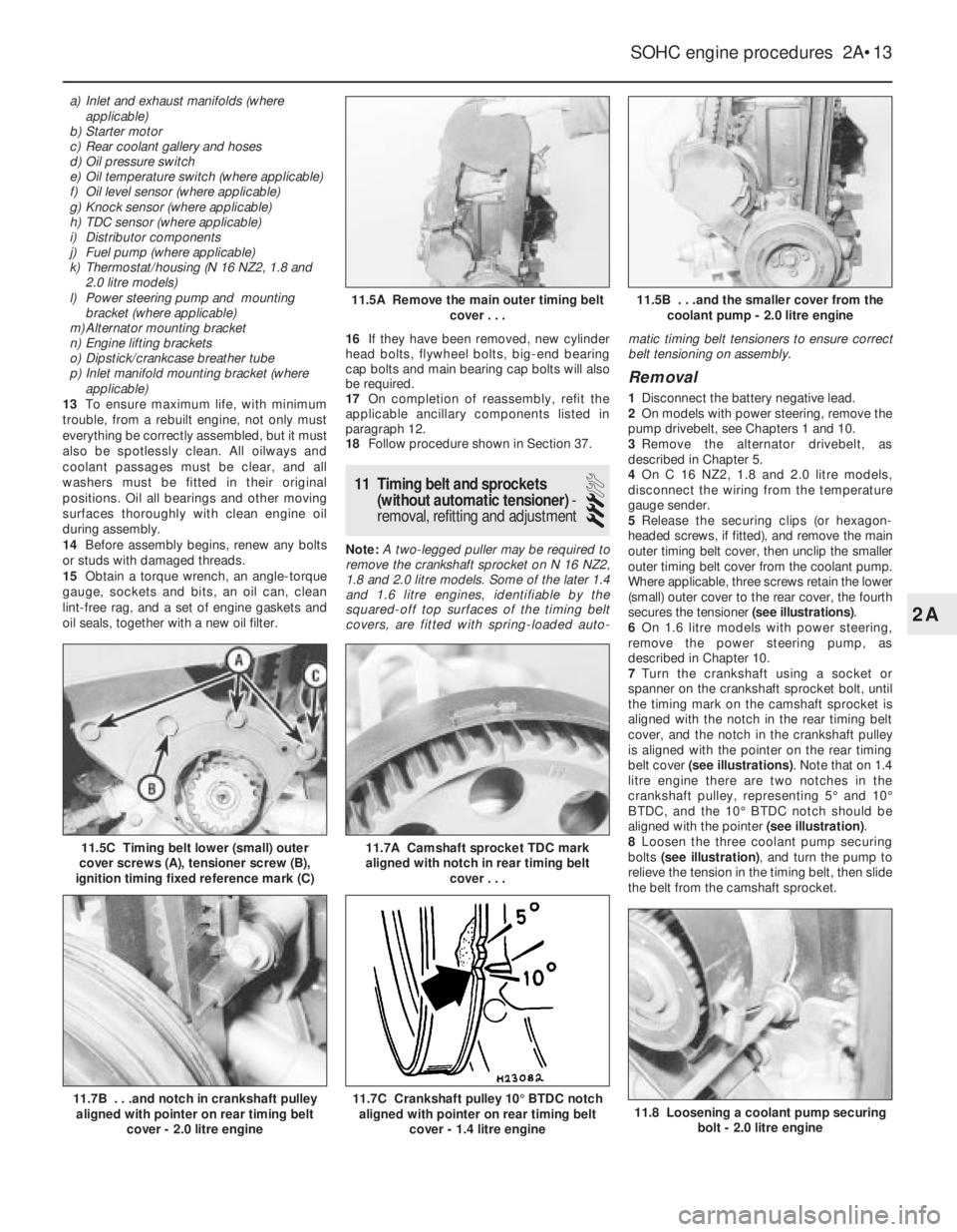
secures the tensioner (see illustrations).
6On 1.6 litre models with power steering,
remove the power steering pump, as
described in Chapter 10.
7Turn the crankshaft using a socket or
spanner on the crankshaft sprocket bolt, until
the timing mark on the camshaft sprocket is
aligned with the notch in the rear timing belt
cover, and the notch in the crankshaft pulley
is aligned with the pointer on the rear timing
belt cover (see illustrations). Note that on 1.4
litre engine there are two notches in the
crankshaft pulley, representing 5°and 10°
BTDC, and the 10°BTDC notch should be
aligned with the pointer (see illustration).
8Loosen the three coolant pump securing
bolts (see illustration), and turn the pump to
relieve the tension in the timing belt, then slide
the belt from the camshaft sprocket.
SOHC engine procedures 2A•13
11.5C Timing belt lower (small) outer
cover screws (A), tensioner screw (B),
ignition timing fixed reference mark (C)
11.8 Loosening a coolant pump securing
bolt - 2.0 litre engine11.7C Crankshaft pulley 10°BTDC notch
aligned with pointer on rear timing belt
cover - 1.4 litre engine11.7B . . .and notch in crankshaft pulley
aligned with pointer on rear timing belt
cover - 2.0 litre engine
11.7A Camshaft sprocket TDC mark
aligned with notch in rear timing belt
cover . . .
11.5B . . .and the smaller cover from the
coolant pump - 2.0 litre engine11.5A Remove the main outer timing belt
cover . . .
2A
Page 224 of 525
28Crankshaft rear oil seal -
renewal
4
Renewal
1With the engine removed from the vehicle,
remove the flywheel, or flexplate (as
applicable) as described in Sections 25 and
26.
2Punch or drill a small hole in the centre of
the now-exposed oil seal. Screw in a
self-tapping screw, and pull on the screw with
pliers to extract the seal. Several attempts
may be necessary. Be careful not to damage
the sealing face of the crankshaft.
3Clean the oil seal seat with a wooden or
plastic scraper.4Grease the lips of the new seal, then tap the
seal into position using a tube, until flush with
the outer faces of the cylinder block and rear
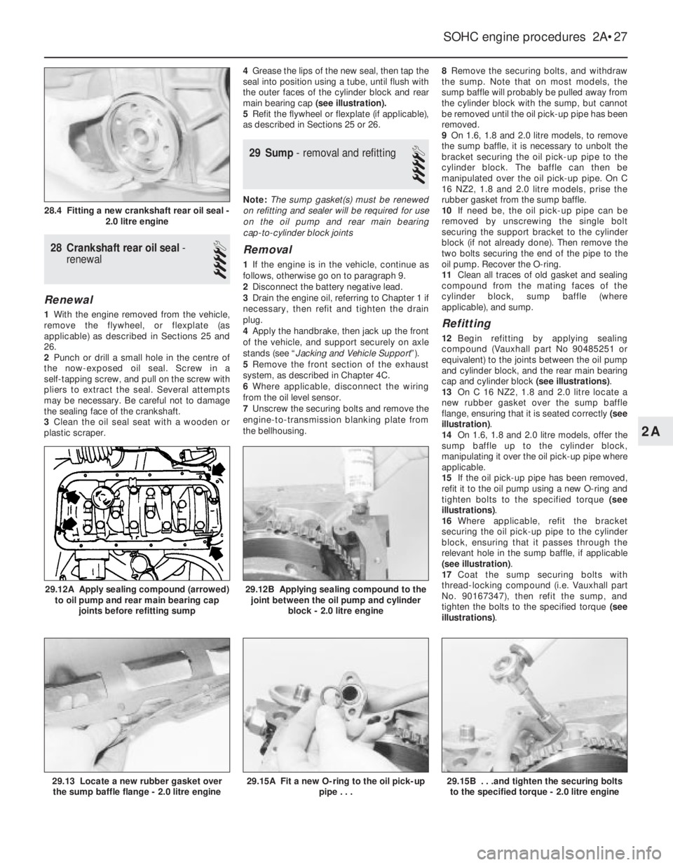
main bearing cap (see illustration).
5Refit the flywheel or flexplate (if applicable),
as described in Sections 25 or 26.
29Sump - removal and refitting
4
Note: The sump gasket(s) must be renewed
on refitting and sealer will be required for use
on the oil pump and rear main bearing
cap-to-cylinder block joints
Removal
1If the engine is in the vehicle, continue as
follows, otherwise go on to paragraph 9.
2Disconnect the battery negative lead.
3Drain the engine oil, referring to Chapter 1 if
necessary, then refit and tighten the drain
plug.
4Apply the handbrake, then jack up the front
of the vehicle, and support securely on axle
stands (see “Jacking and Vehicle Support”).
5Remove the front section of the exhaust
system, as described in Chapter 4C.
6Where applicable, disconnect the wiring
from the oil level sensor.
7Unscrew the securing bolts and remove the
engine-to-transmission blanking plate from
the bellhousing.8Remove the securing bolts, and withdraw
the sump. Note that on most models, the
sump baffle will probably be pulled away from
the cylinder block with the sump, but cannot
be removed until the oil pick-up pipe has been
removed.
9On 1.6, 1.8 and 2.0 litre models, to remove
the sump baffle, it is necessary to unbolt the
bracket securing the oil pick-up pipe to the
cylinder block. The baffle can then be
manipulated over the oil pick-up pipe. On C
16 NZ2, 1.8 and 2.0 litre models, prise the
rubber gasket from the sump baffle.
10If need be, the oil pick-up pipe can be
removed by unscrewing the single bolt
securing the support bracket to the cylinder
block (if not already done). Then remove the
two bolts securing the end of the pipe to the
oil pump. Recover the O-ring.
11Clean all traces of old gasket and sealing
compound from the mating faces of the
cylinder block, sump baffle (where
applicable), and sump.
Refitting
12Begin refitting by applying sealing
compound (Vauxhall part No 90485251 or
equivalent) to the joints between the oil pump
and cylinder block, and the rear main bearing
cap and cylinder block (see illustrations).
13On C 16 NZ2, 1.8 and 2.0 litre locate a
new rubber gasket over the sump baffle
flange, ensuring that it is seated correctly (see
illustration).
14On 1.6, 1.8 and 2.0 litre models, offer the
sump baffle up to the cylinder block,
manipulating it over the oil pick-up pipe where
applicable.
15If the oil pick-up pipe has been removed,
refit it to the oil pump using a new O-ring and
tighten bolts to the specified torque (see
illustrations).
16Where applicable, refit the bracket
securing the oil pick-up pipe to the cylinder
block, ensuring that it passes through the
relevant hole in the sump baffle, if applicable
(see illustration).
17Coat the sump securing bolts with
thread-locking compound (i.e. Vauxhall part
No. 90167347), then refit the sump, and
tighten the bolts to the specified torque (see
illustrations).
SOHC engine procedures 2A•27
29.12B Applying sealing compound to the
joint between the oil pump and cylinder
block - 2.0 litre engine
29.15B . . .and tighten the securing bolts
to the specified torque - 2.0 litre engine29.15A Fit a new O-ring to the oil pick-up
pipe . . .29.13 Locate a new rubber gasket over
the sump baffle flange - 2.0 litre engine
29.12A Apply sealing compound (arrowed)
to oil pump and rear main bearing cap
joints before refitting sump
28.4 Fitting a new crankshaft rear oil seal -
2.0 litre engine
2A
Page 231 of 525
5Note that the rubber plug located next to
the bellhousing flange on the cylinder block
covers the aperture for the installation of a
diagnostic TDC sensor. The sensor, when
connected to a monitoring unit, indicates TDC
from the position of the pins set into the
crankshaft balance weight.
37Examination and renovation
-general
4
General
1With the engine completely stripped, clean all
components and examine them for wear. Each
component should be checked, and where
necessary renewed or renovated, as described
in the relevant Sections of this Chapter.
2Renew main and big-end bearing shells as
a matter of course, unless it is known that
they have had little wear, and are in perfect
condition.
3If in doubt whether to renew a component
that is still just serviceable, consider the time
and effort that will be incurred should the
component fail at an early date after rebuild.
Obviously, the age and expected life of the
vehicle must influence the standards applied.4Gaskets, oil seals and O-rings must all be
renewed as a matter of routine. Flywheel,
cylinder head, and main and big-end bearing
cap bolts must be renewed, because of the
high stress to which they are subjected.
5Renew the engine core plugs while they are
easily accessible, if they show signs of
leakage. Knock out the old plugs with a
hammer and chisel or punch. Clean the plug
seats, smear the new plugs with sealing
compound, and tap them squarely into
position.
38Initial start-up after major
overhaul or repair
2
1Make a final check to ensure that
everything has been reconnected to the
engine, and that no rags or tools have been
left in the engine compartment.
2Check that oil and coolant levels are
correct.
3Start the engine. This may take a little longer
than usual, as fuel is pumped to the engine.
4Check that the oil pressure warning lamp
goes out when the engine starts. This may
take a few seconds as the new oil filter fills
with oil.5Run the engine at a fast tickover, and check
for leaks of oil, fuel and coolant. If a new
camshaft has been fitted, pay careful
attention to the running-in procedure given in
Section 18, paragraphs 17 and 18. Where
applicable, check the power steering and/or
automatic transmission fluid cooler unions for
leakage. Some smoke and odd smells may be
experienced, as assembly lubricants and
sealers burn off the various components.
6Bring the engine to normal operating
temperature. Check the ignition timing, idle
speed and the mixture (where applicable), as
described in Chapter 4A or 4B.
7Allow the engine to cool, then recheck the
oil and coolant levels. Top-up if necessary
8If new bearings, pistons, etc., have been
fitted, the engine should be run-in at reduced
speeds and loads for the first 500 miles (800
km) or so. It is beneficial to change the engine
oil and filter after this mileage.
2A•34SOHC engine procedures
Page 232 of 525
3
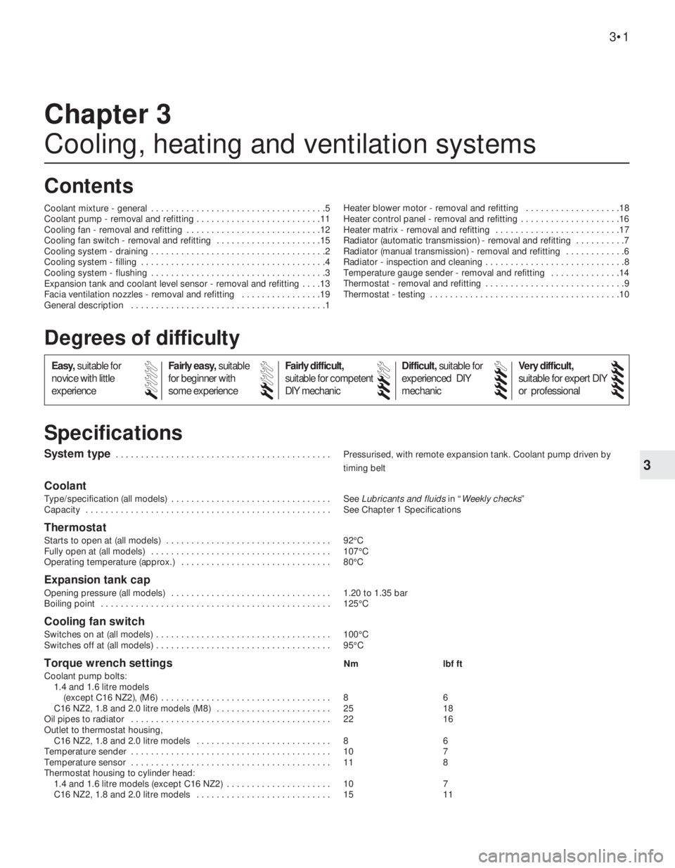
System type . . . . . . . . . . . . . . . . . . . . . . . . . . . . . . . . . . . . . . . . . . . Pressurised, with remote expansion tank. Coolant pump driven by
timing belt
Coolant
Type/specification (all models) . . . . . . . . . . . . . . . . . . . . . . . . . . . . . . . . See Lubricants and fluidsin “Weekly checks”
Capacity . . . . . . . . . . . . . . . . . . . . . . . . . . . . . . . . . . . . . . . . . . . . . . . . . See Chapter 1 Specifications
Thermostat
Starts to open at (all models) . . . . . . . . . . . . . . . . . . . . . . . . . . . . . . . . . 92°C
Fully open at (all models) . . . . . . . . . . . . . . . . . . . . . . . . . . . . . . . . . . . . 107°C
Operating temperature (approx.) . . . . . . . . . . . . . . . . . . . . . . . . . . . . . . 80°C
Expansion tank cap
Opening pressure (all models) . . . . . . . . . . . . . . . . . . . . . . . . . . . . . . . . 1.20 to 1.35 bar
Boiling point . . . . . . . . . . . . . . . . . . . . . . . . . . . . . . . . . . . . . . . . . . . . . . 125°C
Cooling fan switch
Switches on at (all models) . . . . . . . . . . . . . . . . . . . . . . . . . . . . . . . . . . . 100°C
Switches off at (all models) . . . . . . . . . . . . . . . . . . . . . . . . . . . . . . . . . . . 95°C
Torque wrench settingsNm lbf ft
Coolant pump bolts:
1.4 and 1.6 litre models
(except C16 NZ2), (M6) . . . . . . . . . . . . . . . . . . . . . . . . . . . . . . . . . . 8 6
C16 NZ2, 1.8 and 2.0 litre models (M8) . . . . . . . . . . . . . . . . . . . . . . . 25 18
Oil pipes to radiator . . . . . . . . . . . . . . . . . . . . . . . . . . . . . . . . . . . . . . . . 22 16
Outlet to thermostat housing,
C16 NZ2, 1.8 and 2.0 litre models . . . . . . . . . . . . . . . . . . . . . . . . . . . 8 6
Temperature sender . . . . . . . . . . . . . . . . . . . . . . . . . . . . . . . . . . . . . . . . 10 7
Temperature sensor . . . . . . . . . . . . . . . . . . . . . . . . . . . . . . . . . . . . . . . . 11 8
Thermostat housing to cylinder head:
1.4 and 1.6 litre models (except C16 NZ2) . . . . . . . . . . . . . . . . . . . . . 10 7
C16 NZ2, 1.8 and 2.0 litre models . . . . . . . . . . . . . . . . . . . . . . . . . . . 15 11
Chapter 3
Cooling, heating and ventilation systems
Coolant mixture - general . . . . . . . . . . . . . . . . . . . . . . . . . . . . . . . . . . .5
Coolant pump - removal and refitting . . . . . . . . . . . . . . . . . . . . . . . . .11
Cooling fan - removal and refitting . . . . . . . . . . . . . . . . . . . . . . . . . . .12
Cooling fan switch - removal and refitting . . . . . . . . . . . . . . . . . . . . .15
Cooling system - draining . . . . . . . . . . . . . . . . . . . . . . . . . . . . . . . . . . .2
Cooling system - filling . . . . . . . . . . . . . . . . . . . . . . . . . . . . . . . . . . . . .4
Cooling system - flushing . . . . . . . . . . . . . . . . . . . . . . . . . . . . . . . . . . .3
Expansion tank and coolant level sensor - removal and refitting . . . .13
Facia ventilation nozzles - removal and refitting . . . . . . . . . . . . . . . .19
General description . . . . . . . . . . . . . . . . . . . . . . . . . . . . . . . . . . . . . . .1Heater blower motor - removal and refitting . . . . . . . . . . . . . . . . . . .18
Heater control panel - removal and refitting . . . . . . . . . . . . . . . . . . . .16
Heater matrix - removal and refitting . . . . . . . . . . . . . . . . . . . . . . . . .17
Radiator (automatic transmission) - removal and refitting . . . . . . . . . .7
Radiator (manual transmission) - removal and refitting . . . . . . . . . . . .6
Radiator - inspection and cleaning . . . . . . . . . . . . . . . . . . . . . . . . . . . .8
Temperature gauge sender - removal and refitting . . . . . . . . . . . . . .14
Thermostat - removal and refitting . . . . . . . . . . . . . . . . . . . . . . . . . . . .9
Thermostat - testing . . . . . . . . . . . . . . . . . . . . . . . . . . . . . . . . . . . . . .10
3•1
Specifications Contents
Easy,suitable for
novice with little
experienceFairly easy,suitable
for beginner with
some experienceFairly difficult,
suitable for competent
DIY mechanic
Difficult,suitable for
experienced DIY
mechanicVery difficult,
suitable for expert DIY
or professional
Degrees of difficulty
54321
Page 233 of 525
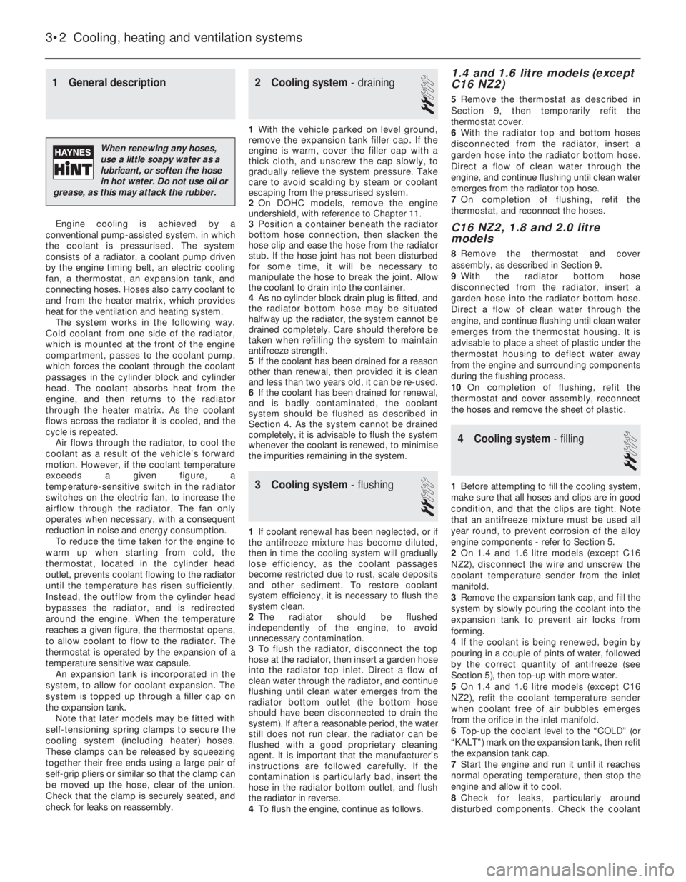
1General description
Engine cooling is achieved by a
conventional pump-assisted system, in which
the coolant is pressurised. The system
consists of a radiator, a coolant pump driven
by the engine timing belt, an electric cooling
fan, a thermostat, an expansion tank, and
connecting hoses. Hoses also carry coolant to
and from the heater matrix, which provides
heat for the ventilation and heating system.
The system works in the following way.
Cold coolant from one side of the radiator,
which is mounted at the front of the engine
compartment, passes to the coolant pump,
which forces the coolant through the coolant
passages in the cylinder block and cylinder
head. The coolant absorbs heat from the
engine, and then returns to the radiator
through the heater matrix. As the coolant
flows across the radiator it is cooled, and the
cycle is repeated.
Air flows through the radiator, to cool the
coolant as a result of the vehicle’s forward
motion. However, if the coolant temperature
exceeds a given figure, a
temperature-sensitive switch in the radiator
switches on the electric fan, to increase the
airflow through the radiator. The fan only
operates when necessary, with a consequent
reduction in noise and energy consumption.
To reduce the time taken for the engine to
warm up when starting from cold, the
thermostat, located in the cylinder head
outlet, prevents coolant flowing to the radiator
until the temperature has risen sufficiently.
Instead, the outflow from the cylinder head
bypasses the radiator, and is redirected
around the engine. When the temperature
reaches a given figure, the thermostat opens,
to allow coolant to flow to the radiator. The
thermostat is operated by the expansion of a
temperature sensitive wax capsule.
An expansion tank is incorporated in the
system, to allow for coolant expansion. The
system is topped up through a filler cap on
the expansion tank.
Note that later models may be fitted with
self-tensioning spring clamps to secure the
cooling system (including heater) hoses.
These clamps can be released by squeezing
together their free ends using a large pair of
self-grip pliers or similar so that the clamp can
be moved up the hose, clear of the union.
Check that the clamp is securely seated, and
check for leaks on reassembly.
2Cooling system -draining
2
1With the vehicle parked on level ground,
remove the expansion tank filler cap. If the
engine is warm, cover the filler cap with a
thick cloth, and unscrew the cap slowly, to
gradually relieve the system pressure. Take
care to avoid scalding by steam or coolant
escaping from the pressurised system.
2On DOHC models, remove the engine
undershield, with reference to Chapter 11.
3Position a container beneath the radiator
bottom hose connection, then slacken the
hose clip and ease the hose from the radiator
stub. If the hose joint has not been disturbed
for some time, it will be necessary to
manipulate the hose to break the joint. Allow
the coolant to drain into the container.
4As no cylinder block drain plug is fitted, and
the radiator bottom hose may be situated
halfway up the radiator, the system cannot be
drained completely. Care should therefore be
taken when refilling the system to maintain
antifreeze strength.
5If the coolant has been drained for a reason
other than renewal, then provided it is clean
and less than two years old, it can be re-used.
6If the coolant has been drained for renewal,
and is badly contaminated, the coolant
system should be flushed as described in
Section 4. As the system cannot be drained
completely, it is advisable to flush the system
whenever the coolant is renewed, to minimise
the impurities remaining in the system.
3Cooling system -flushing
2
1If coolant renewal has been neglected, or if
the antifreeze mixture has become diluted,
then in time the cooling system will gradually
lose efficiency, as the coolant passages
become restricted due to rust, scale deposits
and other sediment. To restore coolant
system efficiency, it is necessary to flush the
system clean.
2The radiator should be flushed
independently of the engine, to avoid
unnecessary contamination.
3To flush the radiator, disconnect the top
hose at the radiator, then insert a garden hose
into the radiator top inlet. Direct a flow of
clean water through the radiator, and continue
flushing until clean water emerges from the
radiator bottom outlet (the bottom hose
should have been disconnected to drain the
system). If after a reasonable period, the water
still does not run clear, the radiator can be
flushed with a good proprietary cleaning
agent. It is important that the manufacturer’s
instructions are followed carefully. If the
contamination is particularly bad, insert the
hose in the radiator bottom outlet, and flush
the radiator in reverse.
4To flush the engine, continue as follows.
1.4 and 1.6 litre models (except
C16 NZ2)
5Remove the thermostat as described in
Section 9, then temporarily refit the
thermostat cover.
6With the radiator top and bottom hoses
disconnected from the radiator, insert a
garden hose into the radiator bottom hose.
Direct a flow of clean water through the
engine, and continue flushing until clean water
emerges from the radiator top hose.
7On completion of flushing, refit the
thermostat, and reconnect the hoses.
C16 NZ2, 1.8 and 2.0 litre
models
8Remove the thermostat and cover
assembly, as described in Section 9.
9With the radiator bottom hose
disconnected from the radiator, insert a
garden hose into the radiator bottom hose.
Direct a flow of clean water through the
engine, and continue flushing until clean water
emerges from the thermostat housing. It is
advisable to place a sheet of plastic under the
thermostat housing to deflect water away
from the engine and surrounding components
during the flushing process.
10On completion of flushing, refit the
thermostat and cover assembly, reconnect
the hoses and remove the sheet of plastic.
4Cooling system -filling
2
1Before attempting to fill the cooling system,
make sure that all hoses and clips are in good
condition, and that the clips are tight. Note
that an antifreeze mixture must be used all
year round, to prevent corrosion of the alloy
engine components -refer to Section 5.
2On 1.4 and 1.6 litre models (except C16
NZ2), disconnect the wire and unscrew the
coolant temperature sender from the inlet
manifold.
3Remove the expansion tank cap, and fill the
system by slowly pouring the coolant into the
expansion tank to prevent air locks from
forming.
4If the coolant is being renewed, begin by
pouring in a couple of pints of water, followed
by the correct quantity of antifreeze (see
Section 5), then top-up with more water.
5On 1.4 and 1.6 litre models (except C16
NZ2), refit the coolant temperature sender
when coolant free of air bubbles emerges
from the orifice in the inlet manifold.
6Top-up the coolant level to the “COLD” (or
“KALT”) mark on the expansion tank, then refit
the expansion tank cap.
7Start the engine and run it until it reaches
normal operating temperature, then stop the
engine and allow it to cool.
8Check for leaks, particularly around
disturbed components. Check the coolant
3•2Cooling, heating and ventilation systems
When renewing any hoses,
use a little soapy water as a
lubricant, or soften the hose
in hot water. Do not use oil or
grease, as this may attack the rubber.
Page 236 of 525
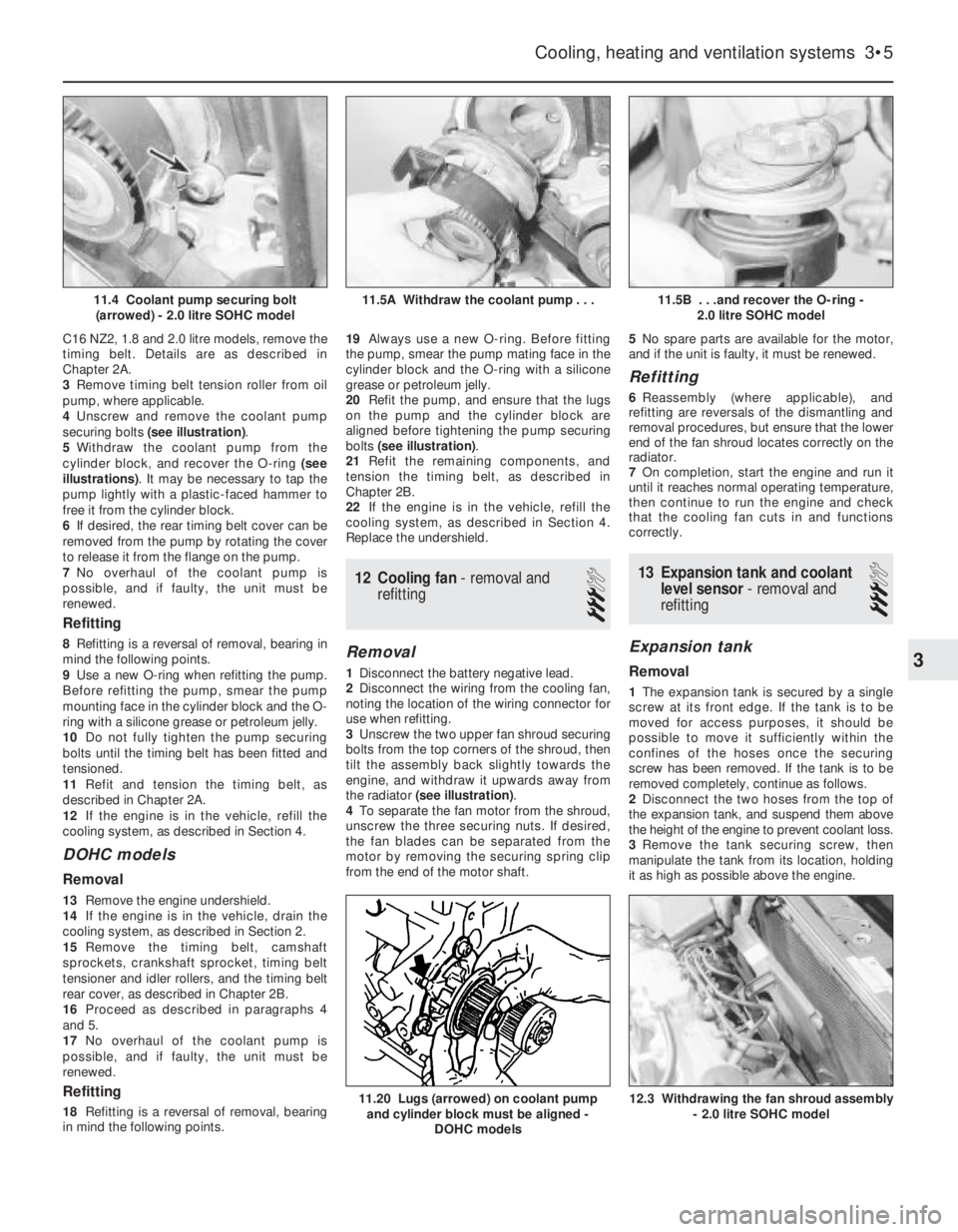
C16 NZ2, 1.8 and 2.0 litre models, remove the
timing belt. Details are as described in
Chapter 2A.
3Remove timing belt tension roller from oil
pump, where applicable.
4Unscrew and remove the coolant pump
securing bolts (see illustration).
5Withdraw the coolant pump from the
cylinder block, and recover the O-ring (see
illustrations). It may be necessary to tap the
pump lightly with a plastic-faced hammer to
free it from the cylinder block.
6If desired, the rear timing belt cover can be
removed from the pump by rotating the cover
to release it from the flange on the pump.
7No overhaul of the coolant pump is
possible, and if faulty, the unit must be
renewed.
Refitting
8Refitting is a reversal of removal, bearing in
mind the following points.
9Use a new O-ring when refitting the pump.
Before refitting the pump, smear the pump
mounting face in the cylinder block and the O-
ring with a silicone grease or petroleum jelly.
10Do not fully tighten the pump securing
bolts until the timing belt has been fitted and
tensioned.
11Refit and tension the timing belt, as
described in Chapter 2A.
12If the engine is in the vehicle, refill the
cooling system, as described in Section 4.
DOHC models
Removal
13Remove the engine undershield.
14If the engine is in the vehicle, drain the
cooling system, as described in Section 2.
15Remove the timing belt, camshaft
sprockets, crankshaft sprocket, timing belt
tensioner and idler rollers, and the timing belt
rear cover, as described in Chapter 2B.
16Proceed as described in paragraphs 4
and 5.
17No overhaul of the coolant pump is
possible, and if faulty, the unit must be
renewed.
Refitting
18Refitting is a reversal of removal, bearing
in mind the following points.19Always use a new O-ring. Before fitting
the pump, smear the pump mating face in the
cylinder block and the O-ring with a silicone
grease or petroleum jelly.
20Refit the pump, and ensure that the lugs
on the pump and the cylinder block are
aligned before tightening the pump securing
bolts (see illustration).
21Refit the remaining components, and
tension the timing belt, as described in
Chapter 2B.
22If the engine is in the vehicle, refill the
cooling system, as described in Section 4.
Replace the undershield.
12Cooling fan - removal and
refitting
3
Removal
1Disconnect the battery negative lead.
2Disconnect the wiring from the cooling fan,
noting the location of the wiring connector for
use when refitting.
3Unscrew the two upper fan shroud securing
bolts from the top corners of the shroud, then
tilt the assembly back slightly towards the
engine, and withdraw it upwards away from
the radiator (see illustration).
4To separate the fan motor from the shroud,
unscrew the three securing nuts. If desired,
the fan blades can be separated from the
motor by removing the securing spring clip
from the end of the motor shaft.5No spare parts are available for the motor,
and if the unit is faulty, it must be renewed.
Refitting
6Reassembly (where applicable), and
refitting are reversals of the dismantling and
removal procedures, but ensure that the lower
end of the fan shroud locates correctly on the
radiator.
7On completion, start the engine and run it
until it reaches normal operating temperature,
then continue to run the engine and check
that the cooling fan cuts in and functions
correctly.
13Expansion tank and coolant
level sensor -removal and
refitting
3
Expansion tank
Removal
1The expansion tank is secured by a single
screw at its front edge. If the tank is to be
moved for access purposes, it should be
possible to move it sufficiently within the
confines of the hoses once the securing
screw has been removed. If the tank is to be
removed completely, continue as follows.
2Disconnect the two hoses from the top of
the expansion tank, and suspend them above
the height of the engine to prevent coolant loss.
3Remove the tank securing screw, then
manipulate the tank from its location, holding
it as high as possible above the engine.
Cooling, heating and ventilation systems 3•5
11.5B . . .and recover the O-ring -
2.0 litre SOHC model
12.3 Withdrawing the fan shroud assembly
- 2.0 litre SOHC model11.20 Lugs (arrowed) on coolant pump
and cylinder block must be aligned -
DOHC models
11.5A Withdraw the coolant pump . . .11.4 Coolant pump securing bolt
(arrowed) - 2.0 litre SOHC model
3