1988 OPEL CALIBRA oil change
[x] Cancel search: oil changePage 175 of 525
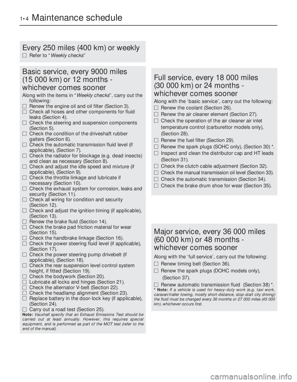
1•4Maintenance schedule
Every 250 miles (400 km) or weekly
MRefer to “Weekly checks”
Basic service, every 9000 miles
(15 000 km) or 12 months -
whichever comes sooner
Along with the items in “Weekly checks”, carry out the
following:
MRenew the engine oil and oil filter (Section 3).
MCheck all hoses and other components for fluid
leaks (Section 4).
MCheck the steering and suspension components
(Section 5).
MCheck the condition of the driveshaft rubber
gaiters (Section 6).
MCheck the automatic transmission fluid level (if
applicable), (Section 7).
MCheck the radiator for blockage (e.g. dead insects)
and clean as necessary (Section 8).
MCheck and adjust the idle speed and mixture (if
applicable), (Section 9).
MCheck the throttle linkage and lubricate if
necessary (Section 10).
MCheck the exhaust system for corrosion, leaks and
security (Section 11).
MCheck all wiring for condition and security
(Section 12).
MCheck and adjust the ignition timing (if applicable),
(Section 13).
MRenew the brake fluid (Section 14).
MCheck the brake pad friction material for wear
(Section 15).
MCheck the handbrake linkage (Section 16).
MCheck the power steering fluid level (if applicable),
(Section 17).
MCheck the power steering pump drivebelt (if
applicable), (Section 18).
MCheck the rear suspension level control system
height, if fitted (Section 19).
MCheck the bodywork (Section 20).
MLubricate all locks and hinges (Section 21).
MCheck the alternator V-belt (Section 22).
MCheck the headlamp alignment (Section 23).
MReplace battery in the door-lock key (if applicable),
(Section 24).
MCarry out a road test (Section 25).
Note: Vauxhall specify that an Exhaust Emissions Test should be
carried out at least annually. However, this requires special
equipment, and is performed as part of the MOT test (refer to the
end of the manual).
Full service, every 18 000 miles
(30 000 km) or 24 months -
whichever comes sooner
Along with the ‘basic service’, carry out the following:
MRenew the coolant (Section 26).
MRenew the air cleaner element (Section 27).
MCheck the operation of the air cleaner air inlet
temperature control (carburettor models only),
(Section 28).
MRenew the fuel filter (Section 29).
MRenew the spark plugs (SOHC only), (Section 30) *.
MInspect and clean the distributor cap and HT leads
(Section 31).
MCheck the clutch cable adjustment (Section 32).
MCheck the manual transmission oil level (Section 33).
MCheck the automatic transmission (Section 34).
MCheck the brake drum shoe for wear (Section 35).
Major service, every 36 000 miles
(60 000 km) or 48 months -
whichever comes sooner
Along with the ‘full service’, carry out the following:
MRenew timing belt (Section 36).
MRenew the spark plugs (DOHC models only),
(Section 37).
MRenew automatic transmission fluid (Section 38) *.
* Note: If a vehicle is used for heavy-duty work (e.g. taxi work,
caravan/trailer towing, mostly short-distance, stop-start city driving)
the fluid must be changed every 36 months or 27 000 miles (45 000
km), whichever occurs first.
Page 186 of 525

3When refitting the distributor cap, check
that the ends of the HT leads are fitted
securely to the cap, plugs and coil. Also make
sure that the spring-tensioned carbon brush
in the centre of the distributor cap moves
freely, and that the HT segments are not worn
excessively.
4Inspect the electrical and vacuum
connections of the ignition/engine
management systems, and make sure that
they are clean and secure.
32Clutch cable check
2
Check the clutch cable adjustment, as
described in Chapter 6.
Check also, the condition of the cable.
Inspect the cable strands for fraying, and
ensure that the cable is correctly routed, to
avoid chafing against surrounding
components. Renew the cable, as described
in Chapter 6, if excessive wear or damage is
evident.
33Manual transmission fluid
check
2
Note:Models built after 1994 it is no longer
necessary to check levels.
1Ensure that the vehicle is on level ground.
2Unscrew the transmission oil level plug,
which is located in the rear left of the
differential housing on F10 and F13
transmissions, and in the rear right of the
differential housing on F16 and F20
transmissions (see illustrations). The oil level
should be up to the bottom of the level plug
orifice.
3If necessary, top-up the oil level through the
breather/filler orifice in the gear selector
cover. Unscrew the breather/filler plug, and
top-up with the specified grade of oil, until oil
just begins to run from the level plug orifice.
Refit the level plug and the breather/filler plug
on completion (see illustrations).
4Renewal of the transmission oil is not
specified by the manufacturers, and no drain
plug is provided. If it is desired to renew the oil
as a precaution, the oil may be drained by
removing the differential cover plate. Use a
new gasket when refitting the cover plate. Fillthe transmission through the breather/filler
orifice, as described previously in this
Section.
5Periodically inspect the transmission for oil
leaks, and check the gear selector linkage
components for wear and smooth operation.
34Automatic transmission
check
2
1Carry out a thorough road test, ensuring
that all gearchanges occur smoothly, without
snatching and with no increase in engine
speed between changes.
2Check the operation of the kickdown.
Check that all gear positions can be engaged
at the appropriate movement of the selector
lever and with the vehicle at rest, check that
the operation of the parking pawl in position
“P” prevents it from being moved. Ensure that
the starter motor will work only with the
selector lever in positions “P” or “N”, and thatthe reversing lamps light only when position
“R” is selected.
3The manufacturer’s schedule calls for a
regular check of the electrical control system
using the special Vauxhall test equipment;
owners will have to have this check carried
out by a Vauxhall dealer.
4Periodically inspect the transmission
casing, checking all joint surfaces and seals
for signs of fluid leaks. If any are found, the
fault must be rectified immediately.
5Check also that the transmission breather
hose (under the battery mounting bracket) is
clear and not blocked, kinked or twisted.
35Brake shoe check
2
Note:On models fitted with rear brake pads,
the handbrake operates brake shoes that are
located inside the rear brake discs.
Refer to Chapter 9, for details.
Every 18 000 miles or 24 months 1•15
33.3A Transmission breather/filler plug
(arrowed) - F16 type transmission33.3B Topping-up the transmission oil
level - F13 type transmission
33.2B Transmission oil level plug
(arrowed) - F16 type transmission (viewed
from below, with driveshaft removed)33.2A Transmission oil level plug
(arrowed) - F13 type transmission (viewed
from above)
1
Page 216 of 525
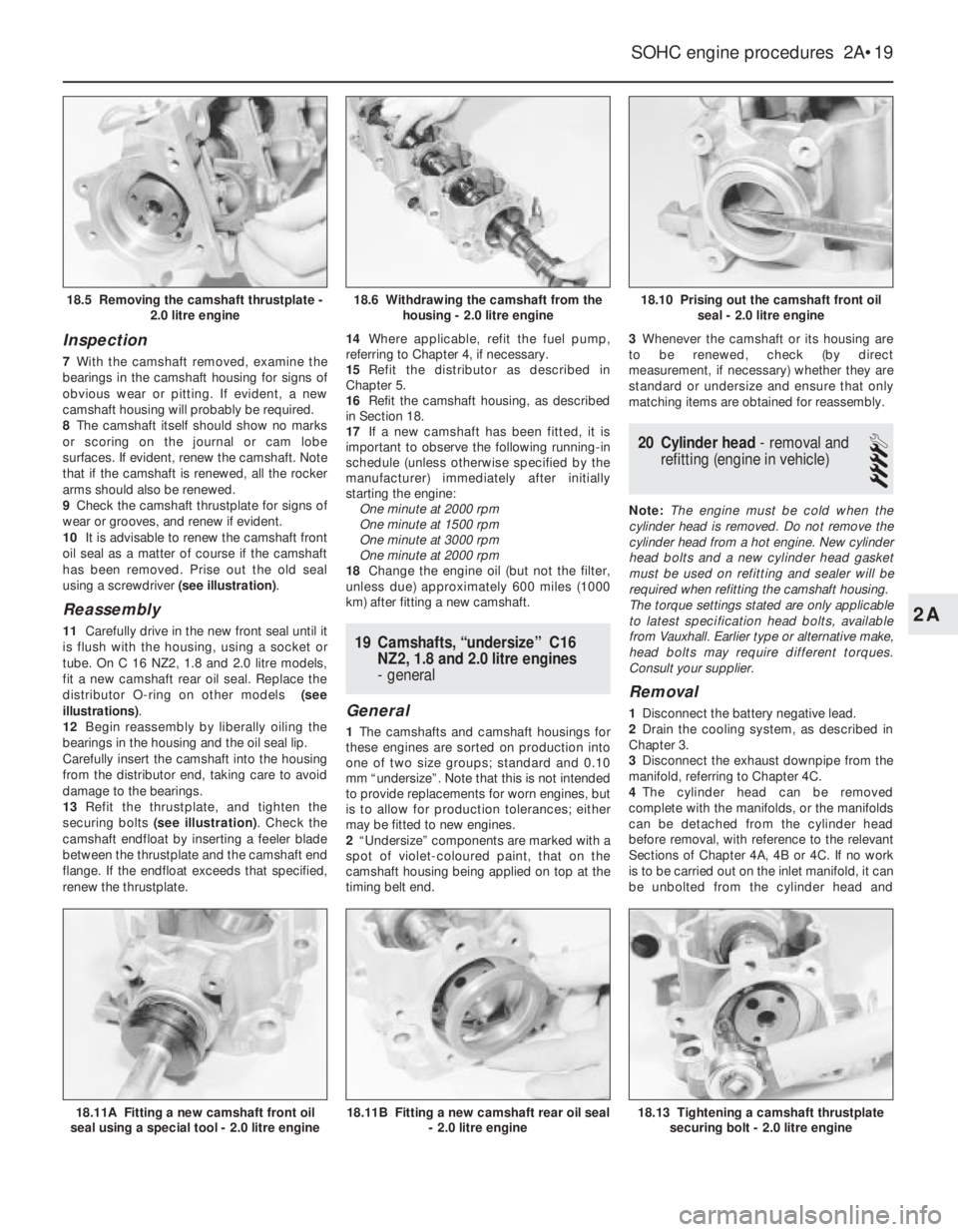
Inspection
7With the camshaft removed, examine the
bearings in the camshaft housing for signs of
obvious wear or pitting. If evident, a new
camshaft housing will probably be required.
8The camshaft itself should show no marks
or scoring on the journal or cam lobe
surfaces. If evident, renew the camshaft. Note
that if the camshaft is renewed, all the rocker
arms should also be renewed.
9Check the camshaft thrustplate for signs of
wear or grooves, and renew if evident.
10It is advisable to renew the camshaft front
oil seal as a matter of course if the camshaft
has been removed. Prise out the old seal
using a screwdriver (see illustration).
Reassembly
11Carefully drive in the new front seal until it
is flush with the housing, using a socket or
tube. On C 16 NZ2, 1.8 and 2.0 litre models,
fit a new camshaft rear oil seal. Replace the
distributor O-ring on other models (see
illustrations).
12Begin reassembly by liberally oiling the
bearings in the housing and the oil seal lip.
Carefully insert the camshaft into the housing
from the distributor end, taking care to avoid
damage to the bearings.
13Refit the thrustplate, and tighten the
securing bolts (see illustration). Check the
camshaft endfloat by inserting a feeler blade
between the thrustplate and the camshaft end
flange. If the endfloat exceeds that specified,
renew the thrustplate.14Where applicable, refit the fuel pump,
referring to Chapter 4, if necessary.
15Refit the distributor as described in
Chapter 5.
16Refit the camshaft housing, as described
in Section 18.
17If a new camshaft has been fitted, it is
important to observe the following running-in
schedule (unless otherwise specified by the
manufacturer) immediately after initially
starting the engine:
One minute at 2000 rpm
One minute at 1500 rpm
One minute at 3000 rpm
One minute at 2000 rpm
18Change the engine oil (but not the filter,
unless due) approximately 600 miles (1000
km) after fitting a new camshaft.19Camshafts, “undersize” C16
NZ2, 1.8 and 2.0 litre engines
- general
General
1The camshafts and camshaft housings for
these engines are sorted on production into
one of two size groups; standard and 0.10
mm “undersize”. Note that this is not intended
to provide replacements for worn engines, but
is to allow for production tolerances; either
may be fitted to new engines.
2“Undersize” components are marked with a
spot of violet-coloured paint, that on the
camshaft housing being applied on top at the
timing belt end.3Whenever the camshaft or its housing are
to be renewed, check (by direct
measurement, if necessary) whether they are
standard or undersize and ensure that only
matching items are obtained for reassembly.
20Cylinder head - removal and
refitting (engine in vehicle)
4
Note: The engine must be cold when the
cylinder head is removed. Do not remove the
cylinder head from a hot engine. New cylinder
head bolts and a new cylinder head gasket
must be used on refitting and sealer will be
required when refitting the camshaft housing.
The torque settings stated are only applicable
to latest specification head bolts, available
from Vauxhall. Earlier type or alternative make,
head bolts may require different torques.
Consult your supplier.
Removal
1Disconnect the battery negative lead.
2Drain the cooling system, as described in
Chapter 3.
3Disconnect the exhaust downpipe from the
manifold, referring to Chapter 4C.
4The cylinder head can be removed
complete with the manifolds, or the manifolds
can be detached from the cylinder head
before removal, with reference to the relevant
Sections of Chapter 4A, 4B or 4C. If no work
is to be carried out on the inlet manifold, it can
be unbolted from the cylinder head and
SOHC engine procedures 2A•19
18.10 Prising out the camshaft front oil
seal - 2.0 litre engine
18.13 Tightening a camshaft thrustplate
securing bolt - 2.0 litre engine18.11B Fitting a new camshaft rear oil seal
- 2.0 litre engine18.11A Fitting a new camshaft front oil
seal using a special tool - 2.0 litre engine
18.6 Withdrawing the camshaft from the
housing - 2.0 litre engine18.5 Removing the camshaft thrustplate -
2.0 litre engine
2A
Page 221 of 525
23Cylinder head - inspection
and renovation
4
Note: Refer to a dealer for advice before
attempting to carry out valve grinding or valve
seat reciting operations, as these operations
may not be possible for the DIY mechanic.
This is due to the fitment of hardened valve
seats for use with unleaded petrol
Inspection
1Remember that the cylinder head is of light
alloy construction and is easily damaged, use
a blunt scraper or rotary wire brush to clean all
traces of carbon deposits from the
combustion spaces and the ports. The valve
stems and valve guides should also be freed
from any carbon deposits. Wash the
combustion spaces and ports down with
paraffin and scrape the cylinder head surface
free of any foreign matter with the side of a
steel rule, or a similar article.
2If the engine is installed in the car, clean the
pistons and the top of the cylinder bores. If
the pistons are still in the block, it is essential
that great care is taken to ensure that no
carbon gets into the cylinder bores. This could
scratch the cylinder walls or cause damage to
the pistons and rings. To ensure this does not
happen, first turn the crankshaft so that two of
the pistons are at the top of their bores. Insert
rag into the other two bores or seal them off
with paper and masking tape. The waterways
should also be covered with small pieces of
masking tape, to prevent particles of carbon
entering the cooling system and damaging the
coolant pump.
3Press a little grease into the gap between
the cylinder walls and the two pistons that are
to be worked on. With a blunt scraper,
carefully scrape away the carbon from the
piston crown, taking great care not to scratch
the aluminium. Also scrape away the carbon
from the surrounding lip of the cylinder wall.
When all carbon has been removed, scrape
away the grease that will now be
contaminated with carbon particles, taking
care not to press any into the bores. To assist
prevention of carbon build-up, the piston
crown can be polished with a metal polish.
Remove the rags or masking tape from the
other two cylinders, and turn the crankshaft
so that the two pistons that were at thebottom are now at the top. Place rag or
masking tape in the cylinders that have been
decarbonised, and continue as just described.
4Examine the heads of the valves for pitting
and burning, especially the heads of the
exhaust valves. The valve seatings should be
examined at the same time. If the pitting on
the valve and seat is very slight, the marks
can be removed by grinding the seats and
valves together with coarse, and then fine,
valve grinding paste.
5Where bad pitting has occurred to the valve
seats, it will be necessary to recut them and fit
new valves. This latter job should be entrusted
to the local dealer or engineering works. In
practice it is very seldom that the seats are so
badly worn. Normally it is the valve that is too
badly worn for refitting, and the owner can
easily buy a new set of valves and match
them to the seats by valve grinding.
Renovation
6Valve grinding is carried out as follows.
Smear a trace of coarse carborundum paste
on the seat face and apply a suction grinder
tool to the valve head. With a semi-rotary
motion, grind the valve head to its seat, lifting
the valve occasionally to redistribute the
grinding paste. When a dull matt even surface
is produced on both the valve seat and the
valve, wipe off the paste and repeat the
process with fine carborundum paste, lifting
and turning the valve to redistribute the paste
as before. A light spring placed under the
valve head will greatly ease this operation.
When a smooth unbroken ring of light grey
matt finish is produced, on both valve and
valve seat faces, the grinding operation is
complete. Carefully clean away every trace of
grinding compound, taking great care to leave
none in the ports or in the valve guides. Clean
the valves and valve seats with a
paraffin-soaked rag, then with a clean rag,
and finally, if an air line is available, blow the
valves, valve guides and valve ports clean.
7Check that all valve springs are intact. If any
one is broken, all should be renewed. Check
the free height of the springs against new
ones. If some springs are not long enough,
replace them all. Springs suffer from fatigue
and it is a good idea to renew them even if
they look serviceable. 8The cylinder head can be checked for
warping either by placing it on a piece of plate
glass or using a straight-edge and feeler
blades. If there is any doubt or if its block face
is corroded, have it re-faced by your dealer or
motor engineering works.
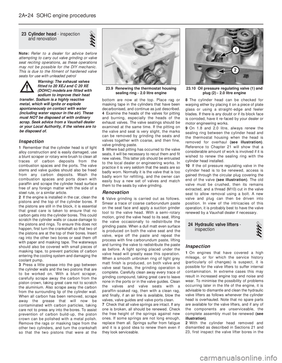
9On 1.8 and 2.0 litre, always renew the
sealing ring between the cylinder head and
the thermostat housing when the head is
removed for overhaul (see illustration).
Reference to Chapter 21 will show that a
considerable amount of work is involved if it is
wished to renew the sealing ring with the
cylinder head installed.
10If the oil pressure regulating valve in the
cylinder head is to be renewed, access is
gained through the circular plug covering the
end of the valve (see illustration). The old
valve must be crushed, then its remains
extracted, and a thread (M10) cut in the valve
seat to allow removal using a bolt. A new
valve and plug can then be driven into
position. In view of the intricacies of this
operation, it is probably best to have the valve
renewed by a Vauxhall dealer if necessary.
24Hydraulic valve lifters -
inspection
4
Inspection
1On engines that have covered a high
mileage, or for which the service history
(particularly oil changes) is suspect, it is
possible for the valve lifters to suffer internal
contamination. In extreme cases this may
result in increased engine top end noise and
wear. To minimise the possibility of problems
occurring later in the life of the engine, it is
advisable to dismantle and clean the hydraulic
valve lifters as follows whenever the cylinder
head is overhauled. Note that no spare parts
are available for the valve lifters, and if any of
the components are unserviceable, the
complete assembly must be renewed (see
illustration).
2With the cylinder head removed and
dismantled as described in Sections 21 and
23, first inspect the valve lifter bores in the
2A•24SOHC engine procedures
23.10 Oil pressure regulating valve (1) and
plug (2) - 2.0 litre engine23.9 Renewing the thermostat housing
sealing ring - 2.0 litre engine
Warning: The exhaust valves
fitted to 20 XEJ and C 20 XE
(DOHC) models are fitted with
sodium to improve their heat
transfer. Sodium is a highly reactive
metal, which will ignite or explode
spontaneously on contact with water
(including water vapour in the air). These
must NOT be disposed of with ordinary
scrap. Seek advice from a Vauxhall dealer
or your Local Authority, if the valves are to
be disposed of.
Page 231 of 525
5Note that the rubber plug located next to
the bellhousing flange on the cylinder block
covers the aperture for the installation of a
diagnostic TDC sensor. The sensor, when
connected to a monitoring unit, indicates TDC
from the position of the pins set into the
crankshaft balance weight.
37Examination and renovation
-general
4
General
1With the engine completely stripped, clean all
components and examine them for wear. Each
component should be checked, and where
necessary renewed or renovated, as described
in the relevant Sections of this Chapter.
2Renew main and big-end bearing shells as
a matter of course, unless it is known that
they have had little wear, and are in perfect
condition.
3If in doubt whether to renew a component
that is still just serviceable, consider the time
and effort that will be incurred should the
component fail at an early date after rebuild.
Obviously, the age and expected life of the
vehicle must influence the standards applied.4Gaskets, oil seals and O-rings must all be
renewed as a matter of routine. Flywheel,
cylinder head, and main and big-end bearing
cap bolts must be renewed, because of the
high stress to which they are subjected.
5Renew the engine core plugs while they are
easily accessible, if they show signs of
leakage. Knock out the old plugs with a
hammer and chisel or punch. Clean the plug
seats, smear the new plugs with sealing
compound, and tap them squarely into
position.
38Initial start-up after major
overhaul or repair
2
1Make a final check to ensure that
everything has been reconnected to the
engine, and that no rags or tools have been
left in the engine compartment.
2Check that oil and coolant levels are
correct.
3Start the engine. This may take a little longer
than usual, as fuel is pumped to the engine.
4Check that the oil pressure warning lamp
goes out when the engine starts. This may
take a few seconds as the new oil filter fills
with oil.5Run the engine at a fast tickover, and check
for leaks of oil, fuel and coolant. If a new
camshaft has been fitted, pay careful
attention to the running-in procedure given in
Section 18, paragraphs 17 and 18. Where
applicable, check the power steering and/or
automatic transmission fluid cooler unions for
leakage. Some smoke and odd smells may be
experienced, as assembly lubricants and
sealers burn off the various components.
6Bring the engine to normal operating
temperature. Check the ignition timing, idle
speed and the mixture (where applicable), as
described in Chapter 4A or 4B.
7Allow the engine to cool, then recheck the
oil and coolant levels. Top-up if necessary
8If new bearings, pistons, etc., have been
fitted, the engine should be run-in at reduced
speeds and loads for the first 500 miles (800
km) or so. It is beneficial to change the engine
oil and filter after this mileage.
2A•34SOHC engine procedures
Page 242 of 525
Spare parts are available from many
sources, for example: Vauxhall dealers, other
garages and accessory shops, and motor
factors. Our advice regarding spare part
sources is as follows.
Officially appointed Vauxhall
dealers
This is the best source of parts that are
peculiar to your car and are otherwise not
generally available (e.g. complete cylinder
heads, transmission components, badges,
interior trim, etc.). It is also the only place at
which you should buy parts if your vehicle is
still under warranty -use of non-Vauxhall
components may invalidate the warranty. To
be sure of obtaining the correct parts it willalways be necessary to give the storeman
your car’s vehicle identification number, and if
possible, to take the “old” parts along for
positive identification. Remember that many
parts are available on a factory exchange
scheme -any parts returned should always be
clean! It obviously makes good sense to go
straight to the specialists on your car for this
type of part for they are best equipped to
supply you.
Other garages and accessory
shops
These are often very good places to buy
materials and components needed for the
maintenance of your car (e.g. oil filters, spark
plugs, bulbs, drivebelts, oils and greases,touch-up paint, filler paste, etc.). They also
sell general accessories, usually have
convenient opening hours, charge lower
prices and can often be found not far from
home.
Motor factors
Good factors will stock all the more
important components that wear out
relatively quickly (e.g. clutch components,
pistons, valves, exhaust systems, brake
cylinders/pipes/hoses/seals/shoes and pads,
etc.). Motor factors will often provide new or
reconditioned components on a part
exchange basis -this can save considerable
amount of money.
Modifications are a continuing and
unpublished process in vehicle manufacture,
quite apart from major model changes. Spare
parts manuals and lists are compiled upon a
numerical basis, the individual vehicle
numbers being essential to correct identifi-
cation of the component required.
When ordering spare parts, always give as
much information as possible. Quote the car
model, year of manufacture and vehicle iden-
tification and/or engine numbers as
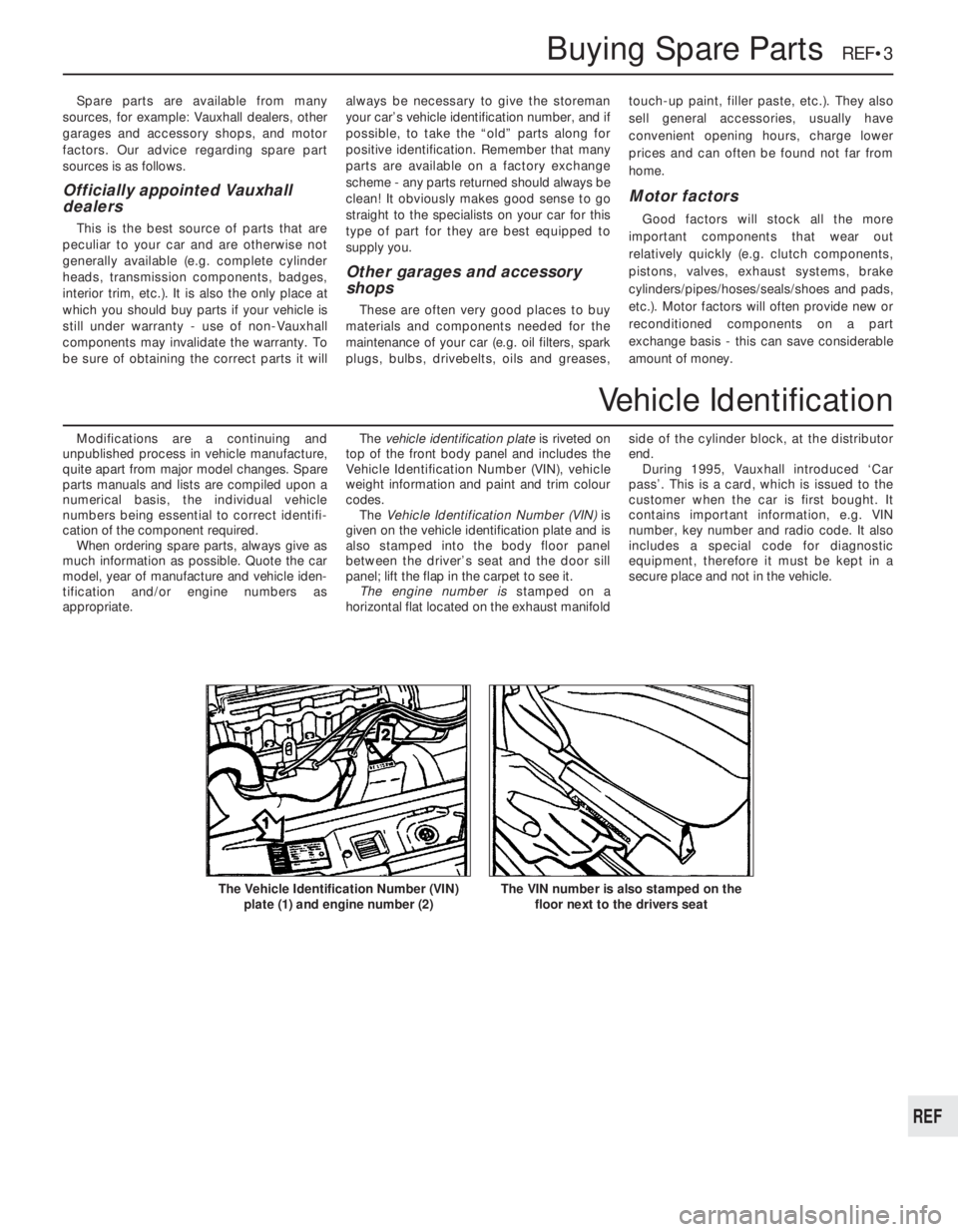
appropriate.The vehicle identification plate is riveted on
top of the front body panel and includes the
Vehicle Identification Number (VIN), vehicle
weight information and paint and trim colour
codes.
The Vehicle Identification Number (VIN) is
given on the vehicle identification plate and is
also stamped into the body floor panel
between the driver’s seat and the door sill
panel; lift the flap in the carpet to see it.
The engine number is stamped on a
horizontal flat located on the exhaust manifoldside of the cylinder block, at the distributor
end.
During 1995, Vauxhall introduced ‘Car
pass’. This is a card, which is issued to the
customer when the car is first bought. It
contains important information, e.g. VIN
number, key number and radio code. It also
includes a special code for diagnostic
equipment, therefore it must be kept in a
secure place and not in the vehicle.
Buying Spare Parts REF•3
The VIN number is also stamped on the
floor next to the drivers seatThe Vehicle Identification Number (VIN)
plate (1) and engine number (2)
REF
Vehicle Identification
Page 255 of 525
Note:Due to the complexity of the automatic transmission, it is difficult
for the home mechanic to properly diagnose and service this unit. For
problems other than the following, the vehicle should be taken to a
dealer service department or automatic transmission specialist. Do not
be too hasty in removing the transmission if a fault is suspected, as
most of the testing is carried out with the unit still fitted.
Fluid leakage
MAutomatic transmission fluid is usually dark in colour. Fluid leaks
should not be confused with engine oil, which can easily be blown
onto the transmission by airflow.
MTo determine the source of a leak, first remove all built-up dirt and
grime from the transmission housing and surrounding areas using
a degreasing agent, or by steam-cleaning. Drive the vehicle at low
speed, so airflow will not blow the leak far from its source. Raise
and support the vehicle, and determine where the leak is coming
from. The following are common areas of leakage:
a)Fluid pan or “sump” (Chapter 1 and 7B).
b)Dipstick tube (Chapter 1 and 7B).
c)Transmission-to-fluid cooler pipes/unions (Chapter 7B).
Transmission fluid brown, or has burned smell
MTransmission fluid level low, or fluid in need of renewal (Chapter 1).
General gear selection problems
MChapter 7B deals with checking and adjusting the selector cable
on automatic transmissions. The following are common problems
that may be caused by a poorly adjusted cable:a)Engine starting in gears other than Park or Neutral.
b)Indicator panel indicating a gear other than the one actually being
used.
c)Vehicle moves when in Park or Neutral.
d)Poor gear shift quality or erratic gear changes.
MRefer to Chapter 7B for the selector cable adjustment procedure.
Transmission will not downshift (kickdown) with
accelerator pedal fully depressed
MLow transmission fluid level (Chapter 1).
MIncorrect selector cable adjustment (Chapter 7B).
Engine will not start in any gear, or starts in gears
other than Park or Neutral
MIncorrect starter/inhibitor switch adjustment (Chapter 7B).
MIncorrect selector cable adjustment (Chapter 7B).
Transmission slips, shifts roughly, is noisy, or has
no drive in forward or reverse gears
MThere are many probable causes for the above problems, but the
home mechanic should be concerned with only one possibility -
fluid level. Before taking the vehicle to a dealer or transmission
specialist, check the fluid level and condition of the fluid as
described in Chapter 1. Correct the fluid level as necessary, or
change the fluid and filter if needed. If the problem persists,
professional help will be necessary.
Clicking or knocking noise on turns (at slow speed
on full-lock)
MLack of constant velocity joint lubricant, possibly due to damaged
gaiter (Chapter 8).
MWorn outer constant velocity joint (Chapter 8).
Vibration when accelerating or decelerating
MWorn inner constant velocity joint (Chapter 8).
MBent or distorted driveshaft (Chapter 8).
REF•16Fault Finding
Automatic transmission
Driveshafts
Noisy in neutral with engine running
MInput shaft bearings worn (noise apparent with clutch pedal
released, but not when depressed), (Chapter 7A).*
MClutch release bearing worn (noise apparent with clutch pedal
depressed, possibly less when released), (Chapter 6).
Noisy in one particular gear
MWorn, damaged or chipped gear teeth (Chapter 7A).*
Difficulty engaging gears
MClutch fault (Chapter 6).
MWorn or damaged gear linkage (Chapter 7A).
MIncorrectly adjusted gear linkage (Chapter 7A).
MWorn synchroniser units (Chapter 7A).*
Jumps out of gear
MWorn or damaged gear linkage (Chapter 7A).
MIncorrectly adjusted gear linkage (Chapter 7A).MWorn synchroniser units (Chapter 7A).*
MWorn selector forks (Chapter 7A).*
Vibration
MLack of oil (Chapter 1).
MWorn bearings (Chapter 7A).*
Lubricant leaks
MLeaking differential output oil seal (Chapter 7A).
MLeaking housing joint (Chapter 7A).*
MLeaking input shaft oil seal (Chapter 7A).*
* Although the corrective action necessary to remedy the symptoms
described is beyond the scope of the home mechanic, the above
information should be helpful in isolating the cause of the condition.
This should enable the owner can communicate clearly with a
professional mechanic.
Manual transmission
Page 265 of 525
oil and filter renewal - 0•17, 1•2, 1•9
oil cooler - 2B•10
oil level - 0•12
oil pump - 2A•28, 2B•9
piston rings - 2A•30
piston/connecting rod - 2A•29
removal - 2A•8, 2B•3
SOHC - 2A•1 et seq
sump - 2A•27, 2B•9
timing belt - 2A•13, 2B•3, 2B•6
undershield - 11•13
valve lifters - 2A•24, 2B•9
valves - 2A•5, 2B•2
Environmental considerations- REF•4
Exhaust manifold- 4C•5
Exhaust system check- 1•11, 4C•5
Expansion tank- 3•5
FFan (radiator)- 3•5
Fault diagnosis- REF•12 et seq
automatic transmission - REF•12, REF•16
braking system - REF•12, REF•17
clutch - REF•12, REF•15
cooling system - REF•12, REF•15
driveshafts - REF•12, REF•16
electrical system - REF•12, REF•18
engine - REF•12, REF•13
fuel and exhaust systems - REF•12, REF•15
manual transmission - REF•12, REF•16
steering - REF•12, REF•17
suspension - REF•12, REF•17
Flexplate (automatic transmission)- 2A•26
Flushing (cooling system)- 3•2
Flywheel- 2A•26
Foglamp- 12•11
Fuel and exhaust (carburettor) systems-
4A•1 et seq
Fuel and exhaust (fuel injection) systems-
4B•1 et seq
Fuel and exhaust systems - emissions-
4C•1 et seq
Fuel and exhaust systems:
accelerator cable - 4A•5
accelerator pedal - 4A•5
air box - 4B•5
air cleaner - 1•3, 1•13, 4A•3, 4B•4
air pump/cut off valve - 4C•2
air temperature control - 4B•5
airflow meters - 4B•12
automatic choke - 4A•9
carbon canister - 4C•4
carburettor - 4A•5, 4A•11
catalytic converter - 4C•3
control unit - 4B•16
depressurising fuel system - 4B•5
EGR components - 4C•2
exhaust manifold - 4C•5
exhaust system check - 1•11, 4C•5
fault diagnosis - REF•12, REF•15
filler cap - 11•13
fuel filters - 1•3, 1•14, 4B•6
fuel flow damper - 4B•8
fuel injector(s) - 4B•13
fuel level sender unit - 4A•4, 4B•8
fuel pressure regulator - 4B•10
fuel pump - 4A•3, 4B•6fuel tank - 4A•4, 4B•7
fuel vapour separator - 4A•4
idle speed/mixture adjustment - 4A•7,
4A•12, 4B•9, 4B•11
inlet manifold - 4A•12, 4B•17
knock sensor - 4B•17
lambda sensor - 4C•4
manifolds - 4A•12, 4B•17, 4C•5
mixture (CO) - 4A•7, 4A•12, 4B•9
oxygen sensor - 4C•4
Pierburg 2E3 - 4A•5
potentiometer - 4B•12, 4B•16
throttle cable - 4A•5
throttle pedal - 4A•5
Fuses- 12•1, 12•3
GGear selector linkage- 7A•2
Gearbox - see Manual or Automatic
transmission
Gearbox oil- 0•17, 1•2, 1•15
Gearchange lever- 7A•3
Glass- 11•9
Glossary of technical terms- REF•20
Glove compartment- 11•18
HHandbrake adjustment- 9•18
Handbrake cables- 9•19
Handbrake lever- 9•20
Handles (door)- 11•7
Hazard warning switch- 12•4
Headlamp alignment- 12•10
Headlamp unit- 12•9
Headlining- 11•19
Heater blower motor switch- 12•4
Heater control panel- 3•6
Heater matrix- 3•7
Heating systems- 3•1 et seq
Horn- 12•8
Hose and fluid leak check- 0•9, 1•9
Hoses brake- 9•18
IIdle speed/mixture/adjustment- 4A•7,
4A•12, 4B•9, 4B•11
Ignition coil- 5•9
Ignition switch- 12•3
Ignition system- 5•2
Igniton timing- 5•2, 5•13
Indicator lamps- 12•11
Indicator switch- 12•4
Injector(s)- 4B•13
Inlet manifold- 4A•12, 4B•17
Input shaft (clutch) oil seal- 7A•4
Instrument panel- 12•6
Interior lamps- 12•8
Interior trim panels- 11•14
Introduction to the Vauxhall Cavalier- 0•4
JJacking and vehicle support- REF•5
Jump starting- 0•7
KKickdown switch - 7B•3
Knock sensor- 4B•17
LLambda sensor- 4C•4
Lamps- 12•8, 12•9
Leaks- 0•9, 1•9
Light switch- 12•4
Locks bonnet- 11•4
Locks door- 11•8
Locks tailgate- 11•6
Lubricants and fluids- 0•17
MMain and big-end bearings- 2A•31
Maintenance - see Routine maintenance
Maintenance schedule- 1•4
Manifolds- 4A•12, 4B•17, 4C•5
Manual transmission- 7A•1 et seq
differential bearing oil seals - 7A•3
fault diagnosis - REF•12, REF•16
gear selector linkage - 7A•2
gearbox oil - 0•17, 1•2, 1•15
gearchange lever - 7A•3
input shaft (clutch) oil seal - 7A•4
overhaul -7A•5
removal and refitting - 7A•4
reversing lamp switch - 7A•6
speedometer drive - 7A•6
Master cylinder (brake)- 9•13
Mirrors- 11•11
Mixture (CO)- 4A•7, 4B•9
MOT test checks- REF•8
Mountings (engine/transmission)- 2A•12,
2B•3
NNumber plate lamp- 12•11
OOil change- 0•17, 1•2, 1•9
Oil cooler- 2B•10
Oil filter- 1•2, 1•9
Oil pressure warning lamp switch- 12•5
Oil pump- 2A•28, 2B•9
Oil seals:
differential bearing - 7A•3
general - REF •4
camshaft - 2A•18, 2B•6
crankshaft - 2A•26, 2B•6, 2B•9
Oils- 0•17, 1•2
Open-circuit, finding - 12•2
Oxygen sensor- 4C•4
PPads (brake)- 9•4
Paintwork damage- 11•2
Parts- REF•3
Pedals
brake - 9•21
clutch - 6•3
throttle - 4A•5
REF•26Index