Page 876 of 1378
Fig. 28: Installing & Aligning Rotor
Courtesy of Chrysler Motors.
6) Carefully slide the distributor into the block until it
seats, keeping the hold down ear aligned to the hole in the block.
7) The rotor should be in the 5 o'clock position with the
trailing edge of the rotor blade lined up with the mark previously
scribed on the distributor housing (number one spark plug wire post
location).
8) install the distributor hold-down clamp bolt and tighten
to 9.5-14 Ft. Lbs. (13-19 N.m).
9) Install the distributor cap. Connect the distributor
electrical connector.
10) Install the electric cooling fan and shroud if
applicable.
11) Connect the negative battery cable.
IGNITION/COIL WIRE REPLACEMENT PRECAUTIONS
Page 877 of 1378

Removal & Installation
Using care, disconnect the spark plug and coil wire boots and
wires. Twist the boot one half turn and pull on the boot to disconnect
the wire.
When replacing the spark plug and coil wires, carefully route
the wires correctly and secure them in their proper channels
retainers.
Failure to route the wires properly can cause the radio to
reproduce ignition noise, cross ignition of the plugs, or can short
circuit the wires to ground.
OVERHAUL
STATOR REPLACEMENT
Disassembly
1) Remove the distributor as specified in DISTRIBUTOR under
REMOVAL & INSTALLATION above in this article.
2) Remove the distributor rotor.
3) Position the distributor in a vise.
4) Remove the distributor gear from the shaft using a small
punch and a hammer to drive out the retaining roll pin. See Fig. 29.
5) Remove the distributor shaft from the distributor housing.
6) Remove the stator retaining screw.
NOTE: Mark the location of the stator position for reassembly
reference.
Fig. 29: Removing Distributor Gear Retaining Roll Pin
Courtesy of Chrysler Motors.
7) Remove stator harness by pushing the grommet through the
distributor housing. Remove stator assembly. See Fig. 30.
Page 880 of 1378
\003
IG NIT IO N S YSTE M - 4 .0 L W /H EI/E ST/E SC ( D ELC O -R EM Y)
�
1 988 J e ep C hero ke e
Distributors & Ignition Systems
HEI, HEI/EST & HEI/EST/ESC IGNITION SYSTEM
Jeep 4.0L
DESCRIPTION
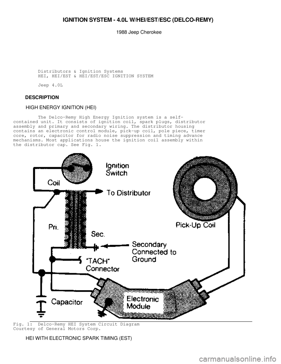
HIGH ENERGY IGNITION (HEI)
The Delco-Remy High Energy Ignition system is a self-
contained unit. It consists of ignition coil, spark plugs, distributor
assembly and primary and secondary wiring. The distributor housing
contains an electronic control module, pick-up coil, pole piece, timer
core, rotor, capacitor for radio noise suppression and timing advance
mechanisms. Most applications house the ignition coil assembly within
the distributor cap. See Fig. 1.
Fig. 1: Delco-Remy HEI System Circuit Diagram
Courtesy of General Motors Corp.
HEI WITH ELECTRONIC SPARK TIMING (EST)
Page 882 of 1378
IGNITION SYSTEM
When the external teeth on the timing core approach, align
with and pass the internal teeth on pole piece, an alternating current
is induced in the pick-up coil windings. This alternating current
signals switching transistors in the HEI module to make or break the
ignition coil primary ground circuit. When the primary ground circuit
is removed, the magnetic field created by the flow of current in the
primary windings collapses across the primary and secondary windings
of the coil. This induces a high-voltage surge in the secondary
windings of the coil. Secondary voltage is then discharged to the
rotor which distributes it to the appropriate spark plug terminal. The
distributor module has different terminal arrangements depending on
application.
Fig. 3: HEI/EST Distributor w/Sealed Module Connectors, External
coil system shown.
Courtesy of General Motors Corp.
EST SYSTEM
Page 883 of 1378

The ECM monitors information concerning crankshaft position,
engine RPM, engine load, atmospheric conditions, engine temperature,
and transmission gear position. This information is used by the ECM to
compute desired spark timing which is relayed to the distributor,
enabling appropriate changes to be made to ignition timing. A back-up
spark advance system is incorporated to signal ignition module in the
event of ECM failure.
CAUTION: Although similar in appearance, components of HEI/EST and
HEI distributors are NOT interchangeable.
All Models With EST
The distributor module is connected to ECM by a 4-wire EST
connector which performs the following functions:
* Terminal "A" of the 4-wire connector is the reference ground
low. It is grounded in the distributor and ensures ground
circuit does not have a voltage drop. If circuit is open,
engine may experience poor performance.
* Terminal "B" of the 4-wire connector is the by-pass circuit.
At about 400 RPM, ECM applies 5 volts to this circuit to
switch spark timing control from module to ECM. An open or
grounded by-pass circuit will set a code 42 and the engine
will operate at base timing, plus a slight amount of advance
built into the module.
* Terminal "C" is the distributor reference High circuit. This
circuit provides the ECM with RPM and crankshaft position
information.
* Terminal "D" is the EST circuit, which triggers the module.
The ECM does not know what actual timing is, but does know
when it receives the reference signal. It will advance or
retard spark from that point. If base timing is set
incorrectly, engine spark curve will be incorrect.
SENSORS
On EST systems, the coolant temperature sensor signals ECM to
advance timing on a cold engine and return timing to programmed
advance curve as engine reaches normal operating temperature. If
engine overheats, spark is retarded to prevent detonation. During
light throttle operation, throttle position sensor input to ECM allows
for additional advance.
Spark advance is also governed by input from engine RPM and
Manifold Absolute Pressure (MAP) sensor. When MAP output voltage is
low (high vacuum), ECM gives less spark advance. More spark advance is\
given when MAP output voltage is high (low vacuum).
ELECTRONIC SPARK CONTROL (ESC) SYSTEM
All Fuel Injected Engines
The basic components of Electronic Spark Control (ESC) system\
are detonation (knock) sensor, HEI/EST distributor, ESC module and
ECM. When detonation (knock) occurs, sensor sends an electrical signal\
to ESC module. The ESC module then sends the signal voltage to the
ECM. When the ECM senses a voltage drop (to less than one volt) on the\
knock sensor signal line, spark timing will be retarded. The ECM will
retard spark timing until all signals from detonation sensor cease.
See Fig. 4 .
Page 884 of 1378

Fig. 4: Circuit Diagram of HEI/EST Ignition System
Courtesy of General Motors Corp.
ADJUSTMENTS
The only adjustments that can be made to HEI/EST igntion
system are basic ignition timing and spark plug gap.
DIAGNOSIS
If reference or EST signals are interrupted due to an open
circuit or a faulty ECM, HEI/EST module will provide a timing signal
based on engine RPM. Engine may continue to run, although less
efficiently. If by-pass signal is lost, by-pass switch will direct RPM
information directly to coil rather than to ECM.
Normally, 5-15 seconds after starting a warm engine, by-pass
signal from ECM will operate a by-pass switch in HEI/EST module. The
HEI/EST module's RPM-controlled timing signal will switch over and RPM
signal will flow directly to the ECM for processing.
Loss of EST signal from ECM when 5-volt by-pass signal is
present will cause engine to stop because HEI/EST module is no longer
sending signals directly to ignition coil. Any loss of EST signal will
stop all flow to coil. If vehicle is restarted, engine will run for a
few seconds and stop when by-pass signal comes back on.
COMPONENT TESTING (HEI)
ELECTRONIC MODULE
NOTE: Testing applies to HEI systems with mechanical weights and
vacuum advance only.
1) An approved electronic module tester must be used to test
the module. Use Module Tester (J-24642-E). Follow manufacturer's
instructions.
2) When installing a new HEI control module, use silicone
Page 885 of 1378
lubricant on module-to-distributor housing contact surface to assist
heat dispersement.
IGNITION COIL
1) Connect an ohmmeter between the negative terminal and the
high voltage terminal. See Fig. 5. Use high resistance scale. If
ohmmeter does not indicate below infinite resistance, coil must be
replaced.
2) Connect ohmmeter between the positive terminal and coil
frame (ground). Use the high resistance scale. If ohmmeter does not
indicate infinite resistance, replace coil.
3) Connect ohmmeter between positive and negative terminals.
Use low resistance scale. Ohmmeter should indicate 0-1 ohm. If not,
replace coil.
Fig. 5: Coil Test Connections
Courtesy of General Motors Corp.
PICK-UP COIL
Page 887 of 1378
The capacitor is used for radio noise supression. Set
ohmmeter at x1000 scale. Disconnect capacitor. Touch ohmmeter leads to
capacitor terminal and ground. Slight needle movement will occur
rapidly and return to infinity. A continuous reading other than
infinity indicates defective capacitor.
COMPONENT TESTING (HEI WITH EST)
COIL RESISTANCE CHECK
Externally Mounted Ignition Coil (Sealed Module Connector
Distributor)
Remove coil connectors and secondary coil wire. In test "A",
use high ohmmeter scale. See Fig. 7. If continuity is present, replace
coil. In test "B", use low ohmmeter scale. Reading should be very low
or near zero. If not, replace coil. In test "C", use high ohmmeter
scale. If there is no continuity, replace coil.
Fig. 7: Testing Ignition Coil Resistance, External coil system shown.
Courtesy of General Motors Corp.
Integrally Mounted Ignition Coil
1) Turn ignition off. Remove the distributor cap and coil
 Carefully slide the distributor into the block until it
seats, keeping the hold down ear aligned to the hole in the block")

 Connect an ohmmeter between the negative terminal and the
high voltage termin")
