Page 845 of 1378

IG NIT IO N S W IT C H & L O CK C YLIN DER
�
1988 J e ep C hero ke e
1988 Ignition Switch & Lock Cylinders
JEEP
DESCRIPTION
The ignition switch and lock cylinder is typically mounted on
the steering column and actuated by an ignition key.
SERVICING
To gain access to ignition components on Jeep vehicles, the
steering column must be removed or lowered and the turn signal switch
must be removed.
CAUTION: The lock plate is held by high spring pressure. DO NOT
remove snap ring without using a compressor tool. If the
steering shaft has standard threads, use Compressor Tool
(J-23653); if the shaft has metric threads use Metric
Forcing Screw (J-23653-4).
CAUTION: Special care must be taken to avoid bumping, jolting or
hammering on the steering shaft and gearshift tube.
REMOVAL & INSTALLATION
LOCK CYLINDER
Removal
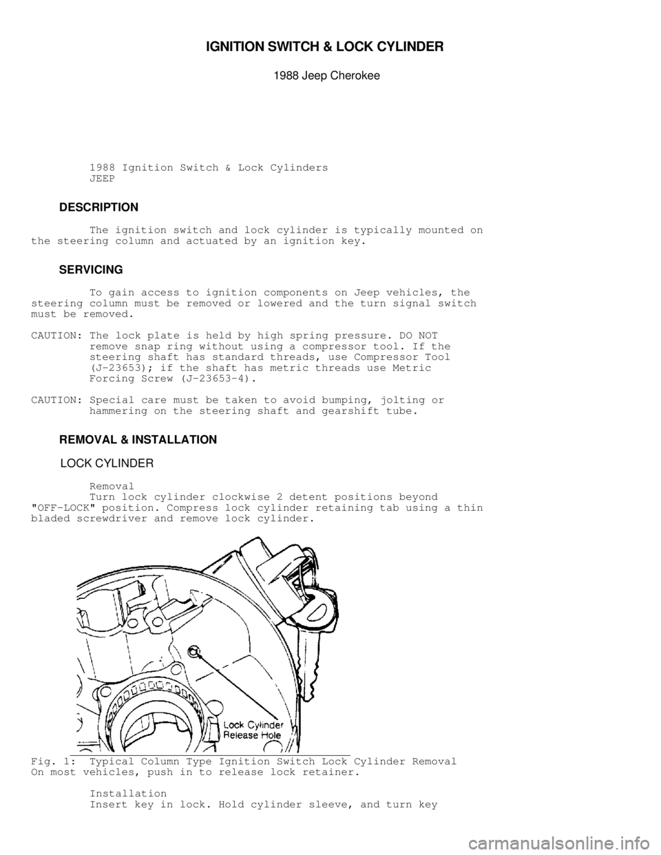
Turn lock cylinder clockwise 2 detent positions beyond
"OFF-LOCK" position. Compress lock cylinder retaining tab using a thin
bladed screwdriver and remove lock cylinder.
Fig. 1: Typical Column Type Ignition Switch Lock Cylinder Removal
On most vehicles, push in to release lock retainer.
Installation
Insert key in lock. Hold cylinder sleeve, and turn key
Page 846 of 1378
clockwise until key stops. Insert cylinder lock into bore with
cylinder tab aligned with keyway in housing. Push cylinder in until it
bottoms. Rotate cylinder counterclockwise to engage lock sector, and
push in until cylinder tab engages in housing groove.
IGNITION SWITCH
Removal
Lower column and remove switch mounting screws. Disconnect
harness connector. Remove switch.
Installation
Move switch slider to "ACC" position. Move switch slider back
2 clicks to "OFF-UNLOCK" position. Insert remote rod in switch slider,
and position switch on column. Do not move slider. Install and tighten
screws.
Fig. 2: Rod-Actuated Ignition Switch
Page 849 of 1378

\003
IG NIT IO N S YSTE M - 4 .0 L W /S O LID S TA TE IG NIT IO N ( S SI)
�1 988 J e ep C hero ke e
DISTRIBUTORS & IGNITION SYSTEMS
Jeep Solid State Ignition
4.0L 6-Cylinder
DESCRIPTION
IGNITION SYSTEM GENERAL DESCRIPTION
The Solid State Ignition (SSI) system features a solid state
Ignition Control Module (ICM)/ignition coil assembly, Electronic
Control Unit (ECU), distributor and engine speed sensor. Other
components include the battery, ignition switch, starter solenoid,
spark plugs and wires, cap and rotor, resistance wire, by-pass wire
and a knock sensor. A sync pulse signal generator (stator) inputs the
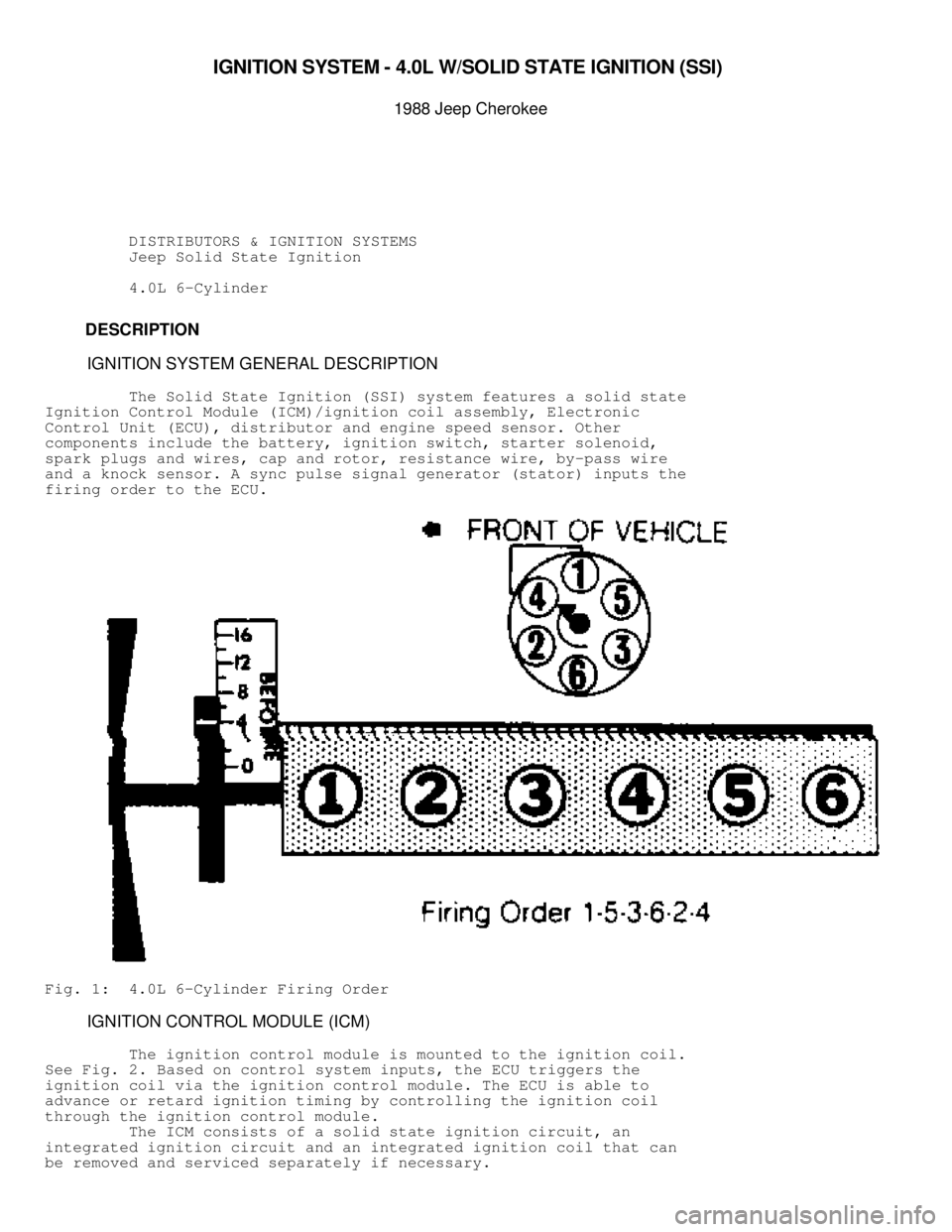
firing order to the ECU.
Fig. 1: 4.0L 6-Cylinder Firing Order
IGNITION CONTROL MODULE (ICM)
The ignition control module is mounted to the ignition coil.
See Fig. 2 . Based on control system inputs, the ECU triggers the
ignition coil via the ignition control module. The ECU is able to
advance or retard ignition timing by controlling the ignition coil
through the ignition control module.
The ICM consists of a solid state ignition circuit, an
integrated ignition circuit and an integrated ignition coil that can
be removed and serviced separately if necessary.
Page 857 of 1378
ignition timing for the particular cylinder is either advanced or
retarded as necessary by the ECU according to sensor inputs.
Fig. 9: View of Engine Speed Sensor, Showing Trigger Notches & TDC
Position
Courtesy of Chrysler Motors.
SYNC PULSE SIGNAL GENERATOR (STATOR)
Page 859 of 1378
pulse signal generator, the magnetic field becomes weaker. This
indicates the position of piston number one to the ECU. When the
trailing edge of the pulse ring leaves the sync pulse signal
generator, the magnetic field becomes stronger. This indicates the
position of piston number six.
The sync pulse signal input and engine speed sensor input
allow the ECU to establish the necessary reference point to
synchronize the fuel injection.
Fig. 11: Sync Pulse Signal Generator Operation
Courtesy of Chrysler Motors.
KNOCK SENSOR
The knock sensor is located on the lower left side of the
engine block just above the oil pan. See Fig. 12. The knock sensor
provides an input to the ECU, indicating detonation (knock) during
engine operation. When knock occurs, the ECU retards the ignition
advance to eliminate the knock at the appropriate cylinder(s).
Page 864 of 1378

Fig. 15. With a hot idle condition, the voltage reading should drop to
between 0.5-1.5 volts.
3) Test ECU terminal "C-6" for the same voltage as described
in step 2) to verify the wiring harness. Repair as necessary.
4) Test the MAP sensor supply voltage at the sensor connector
terminal "C" with the ignition ON. Voltage reading should be between
4.5-5.5 volts. Check that the voltage reading at terminal "C-14" is
also 4.5-5.5 volts.
5) Repair or replace the wire harness as necessary.
6) Test the MAP sensor ground circuit at the sensor connector
terminal "A" and ECU connector terminal "D-3". Repair the wire harness
as necessary.
7) Using an ohmmeter, test the MAP sensor ground circuit at
the ECU connector between terminal "D-3" and terminal "B-ll". If an
open circuit is indicated, check for a defective sensor ground
connection. The MAP sensor ground is located on the right side of the
engine block.
8) If, after performing step 7), the ground connection is
verified to be good, check for a short to 12 volts at terminal "D-3".
If a short is found, repair the short and then replace the ECU.
KNOCK SENSOR TEST
1) Connect Diagnostic Tester M.S. 1700 to the vehicle.
2) Go to "State Display" mode.
3) Start the engine and let idle.
4) Observe knock sensor value.
5) Using the tip of a screwdriver, lightly tap the cylinder
block near the sensor while observing the knock sensor value.
6) The knock sensor value should increase when the cylinder
block is tapped.
7) If the knock sensor value does not increase while tapping
on the cylinder block near the knock sensor, check for proper
connections to the knock sensor. If connections are good, replace
the knock sensor. Refer to REMOVAL & INSTALLATION in this article.
ENGINE SPEED SENSOR TEST
1) Disconnect the engine speed sensor connector from the
ignition control module.
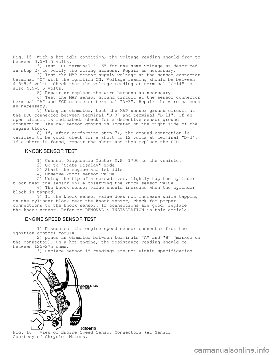
2) place an ohmmeter between terminals "A" and "B" (marked on\
the connector). On a hot engine, the resistance reading should be
between 125-275 ohms.
3) Replace sensor if readings are not within specification.
Fig. 16: View of Engine Speed Sensor Connectors (At Sensor)
Courtesy of Chrysler Motors.
Page 866 of 1378
2) Remove air cleaner assembly.
3) Disconnect the CTS wire connector. See Fig. 17.
4) Remove the CTS from the left side of the engine block.
Fig. 17: Coolant Temperature Sensor (CTS) Connector
Courtesy of Chrysler Motors.
Installation
1) Install the CTS to the cylinder block. Tighten the CTS
to 21 Ft. Lbs. (28 Nm).
2) Connect the CTS wire connector.
3) Install air cleaner assembly.
4) Fill the cooling system.
Page 867 of 1378
MANIFOLD AIR TEMPERATURE (MAT) SENSOR
Removal
1) Disconnect the MAT sensor wire connector. See Fig. 18.
2) Remove the MAT from the intake manifold.
Fig. 18: Manifold Air Temperature (MAT) Sensor Connectors
Courtesy of Chrysler Motors.
Installation
1) Install the MAT sensor to the cylinder block. Tighten the
MAT sensor to 21 Ft. Lbs. (28 Nm).
2) Connect the MAT sensor wire connector.