1988 CITROEN CX oil filter
[x] Cancel search: oil filterPage 212 of 648

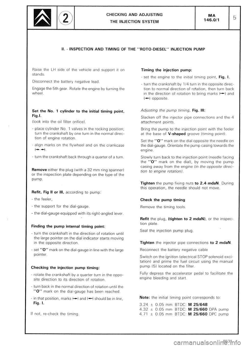
CHECKING AND ADJUSTING
THE INJECTION SYSTEM
II. - INSPECTION AND TIMING OF THE “ROT0-DIESEL” INJECTION PUMP
Raise the LH side of the vehicle and support it on
stands.
Disconnect the battery negative lead.
Engage the 5th gear. Rotate the engine by turning the
wheel.
Set the No. 1 cylinder to the initial timing point,
Fig.1.
(look into the oil filter orifice).
- place cylinder No. 1 valves in the rocking position;
turn the crankshaft by one turn in the normal direc-
tion of engine rotation.
- align marks on the flywheel and on the crankcase
(++I.
- turn the crankshaft back through a quarter of a turn.
Remove either the plug (with a 32 mm ring spanner)
or the inspection plate depending on the type of the
pump.
Refit, Fig II or Ill, according to pump:
- the feeler,
- the support for the dial-gauge.
- the dial-gauge equipped with its right-angled lever.
Finding the pump internal timing point:
- turn the crankshaft in the direction of rotation until
the large pointer on the dial indicator starts moving
in the opposite direction.
- set “0” mark on the dial-gauge in line with the large
pointer.
Checking the injection pump timing:
- rotate the crankshaft by a quarter turn in the oppo-
site direction to its direction of rotation.
- turn back in the normal direction of rotation until the
“0” mark on the dial-gauge has been reached.
- in that position, marks (-1 and (c) should be in line,
Fig. I.
If not, re-check the timing. Timing the injection pump:
- set the engine to the initial trming point, Fig. I.
- turn the crankshaft by 114 turn in the opposite direc-
tion to normal direction of ro’tatron, then turn back
in the direction of rotation to bring marks t-+) and
+-I opposite.
Adjusting the pump timing, Fig. Ill:
Slacken off the injector pipe connections and the 4
attachment points.
Bring the pump to the injection point with the feeler
at the base of V-shaped groove (timing point).
Set the “0” mark on the dial opposite the needle on
the dial-gauge. Orientate the pump casing towards the
engine.
Slowly turn back to the injection point (needle facing
the “0” mark on the dial), by moving the pump
casing away from the engine (in the opposite direc-
tion to engine rotation).
Tighten the pump fixing nuts to 2.4 mdaN. During
this operation, the needle should not move.
Check the pump timing
Remove the timing tools.
Refit the plug, (tighten to 2 mdaN), or the inspec-
tion plate.
Seal the injection pump plug.
Tighten the injector pipe connections to 2 mdaN.
Reconnect the battery negative cable
Switch on the ignition (electrical STOP solenoid exci-
tation) and prime the fuel circuit using the manual
pump (5) located on the filter.
Fully depress the accelerator pedal to facilitate the
engine bleeding and start.
Note: the initial timing point corresponds to:
3.24 -L- 0.05 mm BTDC: M 25/648
4.32 + 0.05 mm BTDC: M 25/660 DPA pump
4.71 f 0.05 mm BTDC: M 25/660 DPC pump
8531
Page 216 of 648

Raise the R.H side of the vehicle and support it on
stands.
Disconnect the negative lead from the battery
Engage the highest gear. Using the road wheel, turn
the engine.
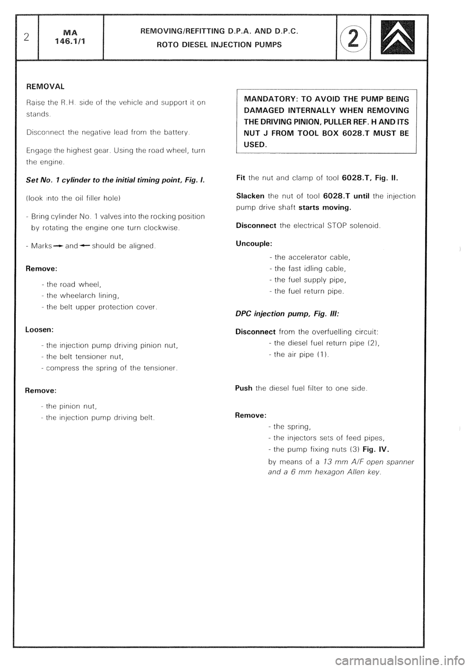
Set No. I cylinder to the initial timing point, Fig. I.
(look into the oil filler hole)
- Bring cylinder No. 1 valves into the rocking position
by rotating the engine one turn clockwise.
- Marks- and- should be aligned.
Remove:
- the road wheel,
- the wheelarch lining,
- the belt upper protection cover.
Loosen:
- the injection pump drrvrng pinion nut,
- the belt tensioner nut,
- compress the spring of the tensioner.
Remove:
- the pinion nut,
- the injection pump driving belt. MANDATORY: TO AVOID THE PUMP BEING
DAMAGED INTERNALLY WHEN REMOVING
THE DRIVING PINION, PULLER REF. H AND ITS
NUT J FROM TOOL BOX 6028.T MUST BE
USED.
Fit the nut and clamp of tool 6028.T, Fig. II.
Slacken the nut of tool 6028.T until the injection
pump drive shaft starts moving.
Disconnect the electrical STOP solenoid
Uncouple:
- the accelerator cable,
- the fast idling cable,
- the fuel supply pipe,
- the fuel return pipe.
DPC injection pump, Fig. ill:
Disconnect from the overfuelling circuit:
- the diesel fuel return pipe (21,
- the air pipe (I 1.
Push the diesel fuel filter to one side
Remove:
- the spring,
- the injectors sets of feed pipes,
- the pump fixing nuts (3) Fig. IV.
by means of a 73 mm A/F open spanner
and a 6 mm hexagon Allen key.
Page 222 of 648

SPECIFICATION AND SPECIAL FEATURES
OF THE AIR SUPPLY SYSTEM
Engines types 829.A5 and J6T.A500 are fitted with a device regulating the temperature of intake air.
This device has been designed for maintaining a minimum temperature of the air drawn into the carburettor
It consists of a thermal sensor and a vacuum capsule operating a flap. Thermal source
The thermal sensor is located in the pipe connecting the air filter to the inlet manifold of the carburettor
This bi-metal type thermostat, is subjected to the inlet air temperature
It controls the opening of valves allowing passage for a depression towards the capsule
This depression is picked up by a union having a calibrated orifice, fitted to the pipe connecting the oil breather
to the intake manifold of the carburettor, and by a T-shaped union situated near the carburettor base plate, so
as to have an action over the engine load.
The thermal sensor allows the depression to circulate when the temperature is below 15°C and stops it when the
temperature exceeds 25°C. Vacuum capsule.
The capsule, located in the inlet of the air filter, is subjected to the depression. When energised, it operates a flap
which lets the heated air coming from a tapping located on the exhaust shield enter. At rest, the flap lets intake
air coming from behind the grill enter.
Page 318 of 648

REPAIR OF THE HYDRAULIC SYSTEM
FITTING PRECAUTIONS
PRECAUTIONS TO BE TAKEN WHEN WORKING ON
THE HYDRAULIC UNITS OR THE SYSTEM
The correct functioning of the entire system presupposes perfect cleanliness of the fluid and the hydraulic
units. Stringent precaut!ons must therefore be taken when working on the hydraulic system and during the
storage of the fluid and components. 1. HYDRAULIC FLUID:
Mineral hydraulic fluid (LHM) is the only suitable type and must be used to the exclusion of all others in the hydrau-
lic system of the car.
This LHM fluid is green in co/our and similar to engine oil.
The use of any other would ruin the rubber rings and seals in the system. 2. RUBBER UNITS AND PARTS:
Suitable components are identified by their green co/our and may only be replaced by genuine replacement
components painted or marked in green.
All rubber components (seals, hoses, diaphragm, etc...) are of a special quality for use with LHM fluid and are
identified by their white or green colour. 3. STORAGE:
Components must be stored, full of fluid and blanked off. Like the piping, they must be protected against shock
and the ingress of dust.
Rubber tubing and joints must be stored away from dust, air, light and heat.
LHM hydraulic fluid must be stored in its original containers carefully sealed. We advise the use of one litre (for
topping up) or five litre cans (for refilling) to avoid having to keep opened containers. 4. CHECKS BEFORE CARRYING OUT WORK:
Before-working on the hydraulic system in case of faulty operation, ensure the following:
a) That the controls or the mechanical linkages of the units or the group of hydraulic units involved are
not stiff in operation
I I
b) and that the HP circuit is under pressure, as follows:
With the engine at idling speed:
- Unscrew the pressure-release screw on the pressure regulator by one turn to one turn and a half: a sound
of leakage should be heard from the regulator.
- Retighten the release screw: cut-out must occur which results in a reduction in the running noise emitted
by the H.P. pump.
If not, check in the following sequence:
- that there is sufficient fluid in the reservoir,
- that the reservoir filter is clean and in good condition,
- that the H.P. pump is primed and there is no air leak on the suction side of the pump,
- that the release screw of the pressure regulator is correctly tightened,
- that sealing ball (2) is in position, (see Fig. I and II, page 5).
Page 385 of 648

Connectors
l.-~l
a,
- Connectors
,”
9 r, 75 Colour
FiY
E
vl
-
M
M
V
V
V
V
M
M
-
N
v
V
M
N
V
-
V
M
V
V
V
-
M
V
2
$
R
V
M
Mv
B
N
BI
B
Mv . -
z
Y
i
r”
B
G Function Function
:
m
.e-
1
-
1
2
3
-
1
2
3
4
1
2
3
4
I
2
3
4
-
1 .-
f
-
M
M
M
-
N
N
M
-
B
B
V
G
N
-
N
M
-
V
V
-
-
M 1
2
3
-
-
-
-
1
2 -
3 -
6 -
4 -
4 -
4 -
3
1
3
-
9
-
6
-
9
-
2
L.
B
-
J
-
v
-
V
-
B
m
sg
ZD
‘N
B
-
B
-
B
-
B
-
V
-
-
-
B Eng. Oil Pressure Sensor
94
95
96 Choke
Diesel Pre Heating
Front Bulb Failure 84
I 8
1
Eng. Oil Sensor
V
J
J Low Fuel Warning Lamp
Fuel Gauge
Fuel Transmitter Earth “Stop” Warning
Hydraulic Warning
Eng. Oil Low Pressure Warning
Water Low Level Warning
Water Temp. Warning
” + Ignition Switch
Battery Charge Warning
Eng. Oil Temp. Warning
Water Low Temp. Warning
2 74
80
79
77
73
80
89
70
100
102
101
98
99
97
85
90
211
212
214
103
103
9
10
11 Instrument Lighting
L/H Dir. Ind. Warning
Seat Belt Warning
+ Ignition Switch (After F2)
Earth 107
R/H Dir. Ind. Warning 105
106
85
211
108
65
66
65 BI
Mv
M
B
Mv
3
L/H Rear Door Warning
Boot Door Warning
R/H Rear Door Warning
L/H Front Door Warning
R/H Front Door Warning
Bonnet Door Warning + Ignition Switch (After F.2)
Earth
Diesel TDC
Tachometer
4
B
G Turbo Pres. Warning
Anti-knock Warning 64
63
Yelow Warning
Red Warning econoscope
5
Brake Pad Wear Warning
Hand Brake Warning
Rear Fog Lamp Warning
Side Lamp Warning
Dipped Beam Warning
Main Beam Warning
Clogged Filter Warning
0 ic 6
R Earth
Test
Warning Rear Bulb
Failure
Unit 81
82
83
7
12 ?ABS Warning
+ Ignition Switch ABS