1988 BMW 3 SERIES driveshafts
[x] Cancel search: driveshaftsPage 4 of 228

0•4Introduction
The E30 3-Series range first became
available in the UK in March 1983, and
continued in production until April 1991, when
the revised E36 3-Series range (not covered
by this manual) was introduced. Convertible
and Touring (Estate) models were introduced
for 1988, and these models have continued in
E30 form to date.
The E28 5-Series models were introduced
in October 1981, and were superseded in
June 1988 by the revised E34 5-Series range,
Touring versions of which became available
from March 1992. Throughout this manual,
E28 models are also referred to as “old-
shape”, while E34 models are designated
“new-shape”.
The models covered by this manual are
equipped with single overhead cam in-line
four- and six-cylinder engines. Early 316 and
518 models are fitted with carburettors, but all
other models are fitted with fuel injection
systems. Transmissions are a five-speed
manual, or three- or four-speed automatic.
The transmission is mounted to the back of
the engine, and power is transmitted to the
fully-independent rear axle through a two-
piece propeller shaft. The final drive unit is
bolted solidly to a frame crossmember, and
drives the rear wheels through driveshaftsequipped with inner and outer constant
velocity joints.
The front suspension is of MacPherson
strut type, with the coil spring/shock absorber
unit making up the upper suspension link. The
rear suspension is made up of coil spring-
over-shock absorber struts, or coil springs
and conventional shock absorbers,
depending on model.
The brakes are disc type at the front, with
either drums or discs at the rear, depending
on model. Servo assistance is standard on all
models. Some later models are equipped with
an Anti-lock Braking System (ABS).
All models are manufactured to fine limits,
and live up to the BMW reputation of quality
workmanship. Although many of the models
covered by this manual appear complex at
first sight, they should present no problems to
the home mechanic.
Note for UK readers
The greater part of this manual was
originally written in the USA. Some of the
photographs used are of American-market
models, but the procedures given are fully
applicable to right-hand-drive models (or have
been amended where necessary).
Acknowledgements
Thanks are due to Champion Spark Plug,
who supplied the illustrations showing spark
plug conditions. Thanks are also due to
Sykes-Pickavant Limited, who provided some
of the workshop tools, and to all those people
at Sparkford who helped in the production of
this manual. Technical writers who
contributed to this project include Robert
Maddox, Mark Ryan and Mike Stubblefield.
We take great pride in the accuracy of
information given in this manual, but
vehicle manufacturers make alterations
and design changes during the production
run of a particular vehicle of which they do
not inform us. No liability can be accepted
by the authors or publishers for loss,
damage or injury caused by any
errors in, or omissions from, the
information given.
Project vehicles
The main project vehicle used in the
preparation of this manual for the UK market
was a 1988 BMW 318i with an M40/B18
engine.
Introduction to the BMW 3- and 5-Series
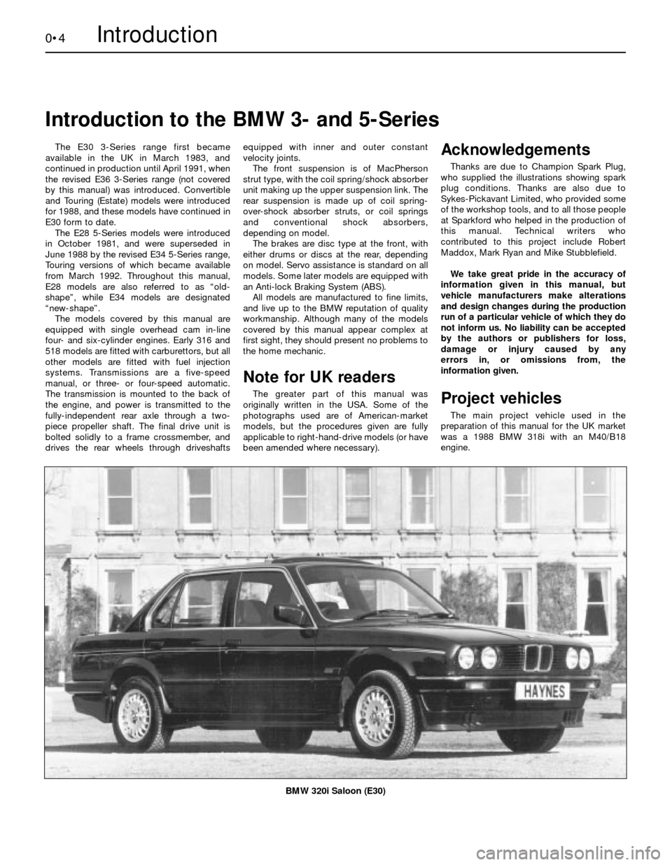
BMW 320i Saloon (E30)
Page 10 of 228

0•10Roadside Repairs
Puddles on the garage floor or drive, or
obvious wetness under the bonnet or
underneath the car, suggest a leak that needs
investigating. It can sometimes be difficult to
decide where the leak is coming from,
especially if the engine bay is very dirty
already. Leaking oil or fluid can also be blown
rearwards by the passage of air under the car,
giving a false impression of where the
problem lies.Warning: Most automotive oils
and fluids are poisonous. Wash
them off skin, and change out of
contaminated clothing, without
delay.
Identifying leaks
The smell of a fluid leaking
from the car may provide a
clue to what’s leaking. Some
fluids are distinctively
coloured. It may help to clean the car
carefully and to park it over some clean
paper overnight as an aid to locating the
source of the leak.
Remember that some leaks may only
occur while the engine is running.
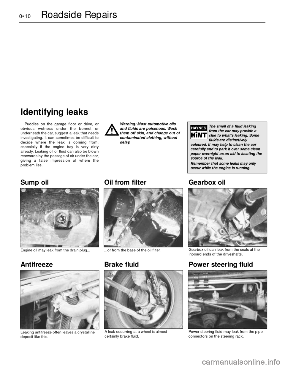
Sump oil Gearbox oil
Brake fluid Power steering fluidOil from filter
Antifreeze
Engine oil may leak from the drain plug......or from the base of the oil filter.
Leaking antifreeze often leaves a crystalline
deposit like this.Gearbox oil can leak from the seals at the
inboard ends of the driveshafts.
A leak occurring at a wheel is almost
certainly brake fluid.Power steering fluid may leak from the pipe
connectors on the steering rack.
Page 204 of 228

REF•3
REF
MOT Test Checks
Exhaust system
MStart the engine. With your assistant
holding a rag over the tailpipe, check the
entire system for leaks. Repair or renew
leaking sections.
Jack up the front and rear of the vehicle,
and securely support it on axle stands.
Position the stands clear of the suspension
assemblies. Ensure that the wheels are
clear of the ground and that the steering
can be turned from lock to lock.
Steering mechanism
MHave your assistant turn the steering from
lock to lock. Check that the steering turns
smoothly, and that no part of the steering
mechanism, including a wheel or tyre, fouls
any brake hose or pipe or any part of the body
structure.
MExamine the steering rack rubber gaiters
for damage or insecurity of the retaining clips.
If power steering is fitted, check for signs of
damage or leakage of the fluid hoses, pipes or
connections. Also check for excessive
stiffness or binding of the steering, a missing
split pin or locking device, or severe corrosion
of the body structure within 30 cm of any
steering component attachment point.
Front and rear suspension and
wheel bearings
MStarting at the front right-hand side, grasp
the roadwheel at the 3 o’clock and 9 o’clock
positions and shake it vigorously. Check for
free play or insecurity at the wheel bearings,
suspension balljoints, or suspension mount-
ings, pivots and attachments.
MNow grasp the wheel at the 12 o’clock and
6 o’clock positions and repeat the previous
inspection. Spin the wheel, and check for
roughness or tightness of the front wheel
bearing.
MIf excess free play is suspected at a
component pivot point, this can be confirmed
by using a large screwdriver or similar tool and
levering between the mounting and the
component attachment. This will confirm
whether the wear is in the pivot bush, its
retaining bolt, or in the mounting itself (the bolt
holes can often become elongated).
MCarry out all the above checks at the other
front wheel, and then at both rear wheels.
Springs and shock absorbers
MExamine the suspension struts (when
applicable) for serious fluid leakage, corrosion,
or damage to the casing. Also check the
security of the mounting points.
MIf coil springs are fitted, check that the
spring ends locate in their seats, and that the
spring is not corroded, cracked or broken.
MIf leaf springs are fitted, check that all
leaves are intact, that the axle is securely
attached to each spring, and that there is no
deterioration of the spring eye mountings,
bushes, and shackles.MThe same general checks apply to vehicles
fitted with other suspension types, such as
torsion bars, hydraulic displacer units, etc.
Ensure that all mountings and attachments are
secure, that there are no signs of excessive
wear, corrosion or damage, and (on hydraulic
types) that there are no fluid leaks or damaged
pipes.
MInspect the shock absorbers for signs of
serious fluid leakage. Check for wear of the
mounting bushes or attachments, or damage
to the body of the unit.
Driveshafts
(fwd vehicles only)
MRotate each front wheel in turn and inspect
the constant velocity joint gaiters for splits or
damage. Also check that each driveshaft is
straight and undamaged.
Braking system
MIf possible without dismantling, check
brake pad wear and disc condition. Ensure
that the friction lining material has not worn
excessively, (A) and that the discs are not
fractured, pitted, scored or badly worn (B).
MExamine all the rigid brake pipes
underneath the vehicle, and the flexible
hose(s) at the rear. Look for corrosion, chafing
or insecurity of the pipes, and for signs of
bulging under pressure, chafing, splits or
deterioration of the flexible hoses.
MLook for signs of fluid leaks at the brake
calipers or on the brake backplates. Repair or
renew leaking components.
MSlowly spin each wheel, while your
assistant depresses and releases the
footbrake. Ensure that each brake is operating
and does not bind when the pedal is released.
3Checks carried out
WITH THE VEHICLE RAISED
AND THE WHEELS FREE TO
TURN
Page 225 of 228

REF•25
REF
Index
Note: References throughout this index relate to Chapter•page number
A
ABS - 9•2
Accelerator cable - 4•9
Acknowledgements - 0•4
Aerial - 12•4
Air bags - 0•5
Air cleaner - 4•8
Air conditioning system - 3•2, 3•7, 3•8,
3•9, 3•10
Air filter - 1•20
Air gap - 5•7
Air intake system - 4•2, 4•14
Airflow meter - 4•15, 6•4
Alternator - 5•10
Anti-lock Braking system (ABS) - 9•2
Anti-roll bar - 10•4, 10•9
Anti-theft audio system - 0•7
Antifreeze - 1•3, 1-8, 3•2
Asbestos - 0•5
ATF - 1•3, 1•13, 1•23
Automatic choke - 4•13
Automatic transmission- 7B•1et seq
Automatic transmission fault finding -
7B•4, REF•13
Automatic transmission fluid - 1•3, 1•13,
1•23
B
Backfire - REF•11
Balljoints - 10•7
Battery - 0•5, 1•16, 5•2
Battery fault - REF•11
Big-end bearings - 2B•17, 2B•21
Bleeding brakes - 9•14
Bleeding clutch - 8•4
Bleeding power steering - 10•16Block - 2B•14, 2B•15
Blower motor - 3•7
Body corrosion - REF•4
Body electrical systems- 12•1et seq
Bodywork and fittings- 11•1et seq
Bonnet - 11•4
Boot lid - 11•6
Boots - 8•9, 10•13
Brake fluid - 1•3, 1•9
Brake lines and hoses - 1•22, 9•13
Braking system- 1•22, 9•1et seq,REF•1,
REF•2, REF•3
Braking system fault finding - REF•14
Bulbs - 12•6
Bumpers - 11•6
Burning - 0•5
C
Cables - 4•9, 5•2, 7B•3, 9•12
Calipers - 9•4
Cam followers - 2B•11
Camshaft - 2A•12, 2B•11
Carburettor - 4•10, 4•11
Carpets - 11•2
Catalytic converter - 4•20, 6•6
Central locking - 12•8
Charging - 1•17, 5•9
Chemicals - REF•18
Choke - 4•13
Clutch and driveline- 8•1et seq
Clutch fault finding - REF•12
Clutch fluid - 1•3, 1•9
CO level adjustment - 1•15, REF•4
Coil - 5•5
Coil springs - 10•7, 10•9
Cold start injectors - 4•17, 4•18
Compression check - 2B•4Compressor - 3•8
Condenser - 3•9
Connecting rods -2B•12, 2B•16, 2B•21
Constant velocity (CV) joint - 8•2, 8•8, 8•9
Continuity check - 12•2
Control arm - 10•4, 10•5
Conversion factors - REF•17
Coolant - 1•3, 1•8
Coolant pump - 3•5
Coolant temperature sender unit - 3•6
Coolant temperature sensor - 6•2
Cooling fan - 3•4
Cooling, heating and air conditioning
systems- 1•21, 1•24, 3•1et seq
Cooling system fault finding - REF•12
Crankshaft - 2A•12, 2A•13, 2A•19, 2B•13,
2B•17, 2B•19, 2B•20
Cruise control - 12•3, 12•8
Crushing - 0•5
Cushion - 11•9
CV joints - 8•2, 8•8, 8•9
Cylinder head - 2A•13, 2B•7, 2B•10, 2B•12
Cylinder honing - 2B•15
D
Dents in bodywork - 11•2
Differential (final drive) - 8•2, 8•10, 8•11
Differential oil -1•3, 1•19, 1•26
Direction indicators - 12•2, 12•3
Discs - 1•22, 9•5
Distributor - 1•18, 5•4
Door - 11•6, 11•8, REF•2
Drivebelts - 1•14
Driveplate - 2A•18
Driveshafts - 1•22, 8•2, 8•9
Drums - 1•23