Page 226 of 284
DEFOGGER SWITCH
1
REMOVAL AND INSTALLATION
8-206 BACK DOOR WINDOW OEFOGGER - Defogger Switch
I
NOEPJAB
1. Defogger switch
NOTE
+* : Refer.to “Service Points . ^
I_ A w
ot Kernoval” 16W932
I
16W976 J
SERVICE POINTS OF REMOVAL
1. REMOVAL OF DEFOGGER SWITCH
lr@rt the special tool into the switch and pry the switch to
remove it from the instrument panel.
INSPECTION
DEFOGGER SWITCH
(1) Remove the defogger switch from the instrument panel
and connect an ohmmeter to the switch side connector.
(2) Operate the switch and check the continuity between the
terminals. * : Indicator light
** : Illumination light
NOTE
0-C indicates that there is continuity between the terminals.
1 STB Revision
~-E
Page 248 of 284
24-12 HEATERS - Heater Unit
I
HEATER UNBT
REMOVAL AND INSTALLATION
Pre-removal Operation
0 Draining of Coolant
(Refer to GROUP 0 LUBRICATION
AND MAINTENANCE-Maintenance
Service)
Post-installation Operation
0 Supplying of Coolant
(Refer to GROUP 0 LUBRICATION
AND MAINTENANCE-Maintenance
Service) Removal steps
l *
I, Heater hose connection
+* l 4
2. Instrument panel
3. Duct
4. Center ventilator duct
5. Heater unit
NOTE
(1) Reverse the removal procedures to reinstall.
(2) +e : Refer to “Service Points of Removal”
(3) l
+ : Refer to “Service Points of Installation”
2OW823
SERVICE POINTS OF REMOVAL
1. DISCONNECTION OF HEATER HOSES (1) Remove the air filter.
(2) Set the temperature lever to the far
(3) Remove the radiator drain plug and
engine coolant.
(4) Remove the heater hose clamp, and
heater hose.
N24lBAE right position.
then drain the
disconnect the
ETB Revision
Page 249 of 284

HEATERS - Heater Unit 24-13
2. REMOVAL OF INSTRUMENT PANEL
Refer to GROUP 23 BODY-Instrument Panel.
INSPEGTION N24cAa
l
Check the damper and link mechanism for operation.
l Check the heater core for clogging or water leakage.
l Check the water valve for operation and clogging.
EATER CORE REPLACEMENT
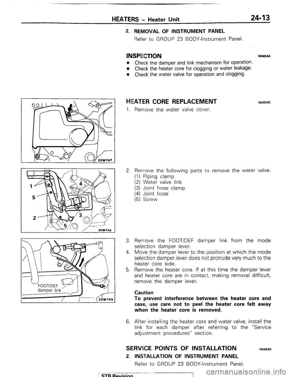
I. Remove the water valve cover.
2. Remove the following parts to remove the water valve.
(1) Piping clamp
(2) Water valve link
(3) Joint hose clamp
(4) Joint hose
(5) Screw
3. Remove the FOOT/DEF damper link from the mode
selection damper lever.
4. Move the damper lever to the position at which the mode
selection damper lever does not protrude very much to the
heater core side.
5. Remove the heater core. If at this time the damper lever
and heater core are in contact, making removal difficult,
remove the damper lever.
Caution
To prevent interference between the heater
core and
case, use care not to peel the heater
core felt away
when the heater core is removed.
6. After installing the heater core and water valve, install the
link for each damper after referring to the “Service
adjustment procedures” section.
SERWOCE POINTS OF INSTALLATION
2. INSTALLATION OF INSTRUMENT PANEL
Refer to GROUP 23 BODY-Instrument Panel.
N241EAD
1 STB Revision
Page 252 of 284
24-16 HEATER? - Ventilators
VENTILATORS
REMOVAL AND INSTALLATON (Ventilators of instrument panel) N24MA-
‘16
zowaa I4
Removal steps
1. Demister grill
2. Lap heater garnish
3. Lap heater duct (B)
4. Lap heater duct (C)
5. Defroster duct (L.H.)
6. Lap heater duct (A)
7. Defroster duct (R.H.)
8. Air duct (R.H.) (Only vehicles with air
conditioner)
9. Lap heater duct (A)
10. Air duct (L.H.) (Only vehicles with air
conditioner) 11. Instrument panel
12. Defroster duct
13. Center ventilator duct
14. Center air outlet
15. Knob
16. Air duct
17. Side air outlet
NOTE
(1) Reverse the removal procedures to reinstall.
(2) +e : Refer to “Service Points of Removal”
SERVICE POINTS OF REMOVAL N24MBAG
1. REMOVAL OF DEMISTER GRILL
While using a screwdriver to pry the lock of the demister
grill, use another screwdriver to pry the end of the
demister grill to remove it.
levision
Page 253 of 284

HEATERS - Ventilators 24-17
2OW75l
2OW759
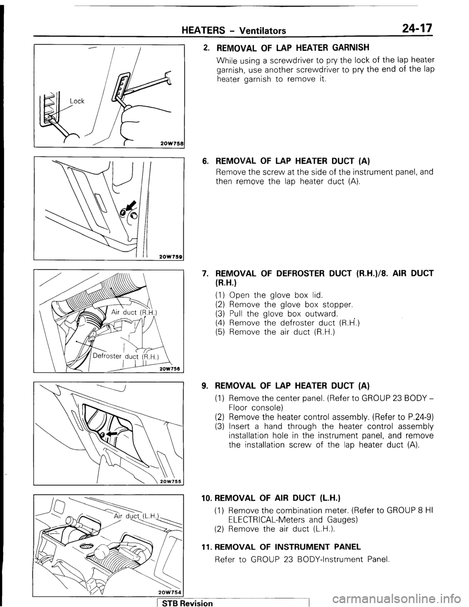
2. REMOVAL OF LAP HEATER GARNISH
While using a screwdriver to pry the lock of the lap heater
garnish, use another screwdriver to pry the end of the lap
heater garnish to remove it.
6. REMOVAL OF LAP HEATER DUCT (A)
Remove the screw at the side of the instrument panel, and
then remove the lap heater duct (A).
7. REMOVAL OF DEFROSTER DUCT (R.H.)/8. AIR DUCT
(R.H.)
(1) Open the glove box lid.
(2) Remove the glove box stopper.
(3) Pull the glove box outward.
(4) Remove the defroster duct (R.H’.)
(5) Remove the air duct (R.H.)
9. REMOVAL OF LAP HEATER DUCT (A)
(1) Remove the center panel. (Refer to GROUP 23 BODY -
Floor console)
(2) Remove the heater control assembly. (Refer to P.24-9)
(3) Insert a hand through the heater control assembly
installation hole in the instrument panel, and remove
the installation screw of the lap heater duct (A).
1 STB Revision 10. REMOVAL OF AIR DUCT (L.H.)
(1) Remove the combination meter. (Refer to GROUP 8 HI
ELECTRICAL-Meters and Gauges)
(2) Remove the air duct (L.H.).
11. REMOVAL OF INSTRUMENT PANEL
Refer to GROUP 23 BODY-Instrument Panel.
Page:
< prev 1-8 9-16 17-24