1987 MAZDA 626 wheel
[x] Cancel search: wheelPage 1816 of 1865
30 TECHNICAL DATA
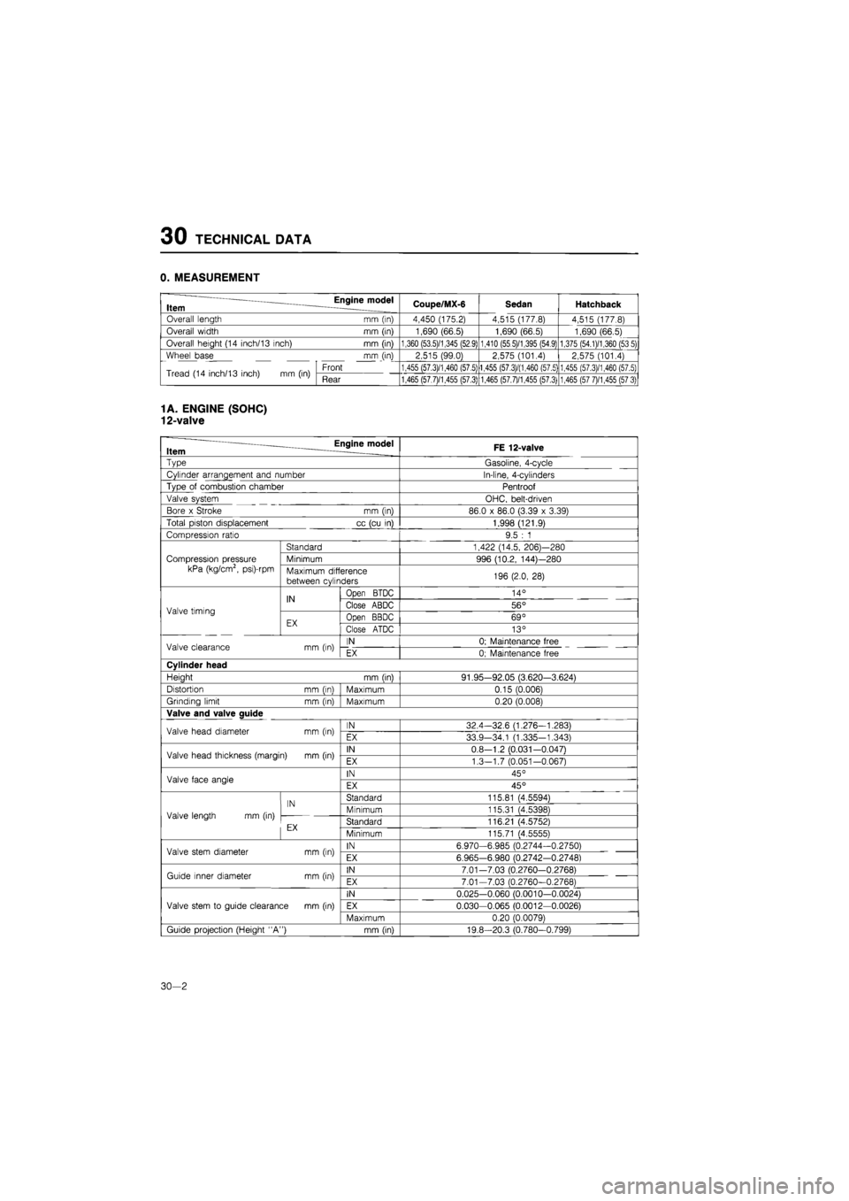
0. MEASUREMENT
Item Engine model Coupe/MX-6 Sedan Hatchback
Overall length mm (in) 4,450 (175.2) 4,515 (177.8) 4,515 (177.8)
Overall width mm (in) 1,690 (66.5) 1,690 (66.5) 1,690 (66.5)
Overall height (14 inch/13 inch) mm (in) 1,360 (53.5)/1,345 (52.9) 1,410 (55 5)/1,395 (54.9) 1,375 (54.1)/1,360 (53 5)
Wheel base mm (in) 2,515 (99.0) 2,575 (101.4) 2,575 (101.4)
Tread (14 inch/13 inch)
mm (in)
Front 1,455 (57.3)/1,460 (57.5) 1,455 (57.3)/(1,460 (57.5) 1,455 (57.3)/1,460 (57.5) Tread (14 inch/13 inch)
mm (in)
Rear 1,465 (57.7)/1,455 (57.3) 1,465 (57.7)/1,455 (57.3) 1,465 (57 7)/1,455 (57 3)
1
A. ENGINE (SOHC)
12-valve
— Engine model Item FE 12-valve
~vpe
Gasoline, 4-cycle
Cylinder arrangement and number In-line, 4-cylinders
Type
of
combustion chamber Pentroof
Valve system OHC, belt-driven
Bore
x
Stroke
mm (in)
86.0
x
86.0 (3.39
x
3.39)
Total piston displacement
cc
(cu
in)
1,998 (121.9)
Compression ratio 9.5
: 1
Compression pressure
kPa (kg/cm2, psi)-rpm
Standard 1,422 (14.5, 206)—280
Compression pressure
kPa (kg/cm2, psi)-rpm
Minimum 996 (10.2, 144)—280 Compression pressure
kPa (kg/cm2, psi)-rpm Maximum difference
between cylinders 196 (2.0,
28)
Valve timing
IN
Open
BTDC 14°
Valve timing
IN Close ABDC 56° Valve timing
EX Open BBDC 69° Valve timing
EX Close ATDC 13°
Valve clearance
mm (in)
IN 0; Maintenance free Valve clearance
mm (in)
EX 0; Maintenance free
Cylinder head
Heiaht
mm (inl
91.95-92.05 (3.620-3.624)
Distortion
mm (inl
Maximum 0.15 (0.006)
Grinding limit
mm (in)
Maximum 0.20 (0.008)
Valve and valve auide
Valve head diameter
mm (in)
IN 32.4-32.6 (1.276—1.283) Valve head diameter
mm (in)
EX 33.9-34.1 (1.335-1.343)
Valve head thickness (margin)
mm (in)
IN 0.8-1.2 (0.031—0.0471 Valve head thickness (margin)
mm (in)
EX 1.3—1.7 (0.051-0.067)
Valve face angle IN 45° Valve face angle EX 45°
Valve length
mm (in)
IN Standard 115.81 (4.55941
Valve length
mm (in)
IN Minimum 115.31 (4.5398) Valve length
mm (in)
cv Standard 116.21 (4.5752)
Minimum 115.71 (4.55551
Valve stem diameter
mm (in)
IN 6.970-6.985 (0.2744-0.2750) Valve stem diameter
mm (in)
EX 6.965-6.980 (0.2742-0.27481
Guide inner diameter
mm (in)
IN 7.01-7.03 (0,2760-0.2768) Guide inner diameter
mm (in)
EX 7.01-7.03 (0.2760-0.27681
Valve stem
to
guide clearance
mm (in)
IN 0.025-0.060 (0.0010-0.0024)
Valve stem
to
guide clearance
mm (in)
EX 0.030-0.065 (0.0012—0.0026) Valve stem
to
guide clearance
mm (in)
Maximum 0.20 (0.00791
Guide projection (Height "A")
mm (in)
19.8-20.3 (0.780-0.799)
30—2
Page 1835 of 1865
TECHNICAL DATA 30
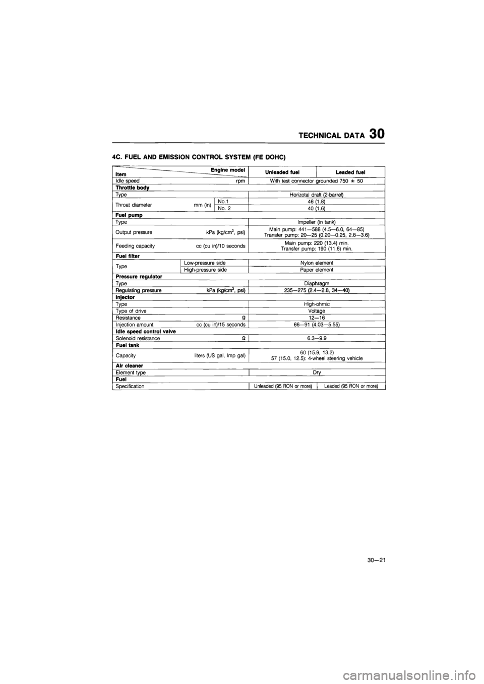
4C. FUEL AND EMISSION CONTROL SYSTEM (FE DOHC)
Item ^Engine^model Unleaded fuel Leaded fuel
Idle speed rpm With test connector grounded 750
± 50
Throttle body
Type Horizotal draft (2-barrel)
Throat diameter mm (in) No.1 46 (1.8) Throat diameter mm (in) No.
2
40 (1.6)
Fuel pump
Type Impeller (in tank)
Output pressure kPa (kg/cm2,
psi)
Main pump: 441—588 (4.5—6.0, 64—85)
Transfer pump: 20—25 (0.20—0.25, 2.8—3.6)
Feeding capacity cc (cu in)/10 seconds Main pump: 220 (13.4) min. Transfer pump: 190 (11.6) min.
Fuel filter
Type Low-pressure side Nylon element Type High-pressure side Paper element
Pressure regulator
Type Diaphragm
Regulating pressure kPa (kg/cm2, psi) 235-275 (2.4 -2.8, 34-40)
Injector
Type High-ohmic
Type
of
drive Voltage
Resistance
ft
12--16
Injection amount cc (cu in)/15 seconds 66-91 (4.03-5.55)
Idle speed control valve
Solenoid resistance Q 6.3--9.9
Fuel tank
Capacity liters (US gal, Imp gal) 60 (15.9, 13.2) 57 (15.0, 12.5): 4-wheel steering vehicle
Air cleaner
Element type Dry
Fuel
Specification Unleaded (95 RON
or
more) i Leaded (95 RON
or
more)
30-21
Page 1839 of 1865
TECHNICAL DATA 30
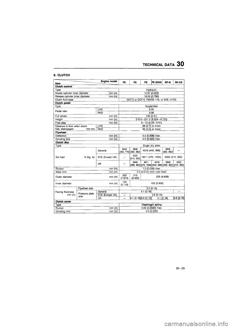
6. CLUTCH
Item Engine model F6 F8 FE FE DOHC RF-N RF-CX
Clutch control
Type Hydraulic
Master cylinder inner diameter mm (in) 15.87 (0.625)
Release cylinder inner diameter mm (in) 19.05 (0.750)
Clutch fluid type DOT-3
or
DOT-4, FMVSS 116,
or
SAE J1703
Clutch pedal
Type Suspended
Pedal ratio LHD 6.00 Pedal ratio RHD 5.96
Full stroke mm (in) 135 (5.31)
Height mm (in) 216.5-221.5 (8.524—8.720)
Free play mm (in) 5—13 (0.20—0.51)
Distance
to
floor when clutch LHD 68 (2.7)
or
more
fully disengaged mm (in) RHD 85 (3.3)
or
more
Flywheel
Deflection mm (in) 0.2 (0.008) max.
Grinding limit mm (in) 0.5 (0.020) max.
Clutch disc
Type Single
dry
plate
General 3434 (350, 770) 3846 (392, 862) 4316 (440, 968) 3846 (392, 862)
—
Set load N (kg,
lb)
ECE (Except UK)
—
4022
(410, 902) 4611 (470, 1034) 4022 (410, 902)
UK
—
3846
(392, 862)
4611
(470, 1034)
4316
(440, 968) 3846
I
4022
(392, 862)|(410, 902)
Runout mm (in) 1.0 (0.039) max.
Wear limit mm (in) 0.3 (0.012) from rivet head
Outer diameter mm (in) 200 (7.874) 215
(8.465) 225 (8.858)
Inner diameter mm (in) 130 (5.118) 150 (5.906)
Flywheel side 3.5 (0.14)
Facing thickness Pressure plate
side
General 4.1 (0.16)
-
mm (in) Pressure plate
side ECE (Except UK)
—
3.8 (0.15) Pressure plate
side UK
—
4.1
ro.16)
3.8 (0.15) 4.1 (0.16) 3.8
(0.15)
Clutch cover
Type
Diaphragm spring
Runout mm (in) 0.05 (0.0020) max.
Grindina limit mm (in) 0.5 (0.020)
30—25
Page 1850 of 1865
30 TECHNICAL DATA
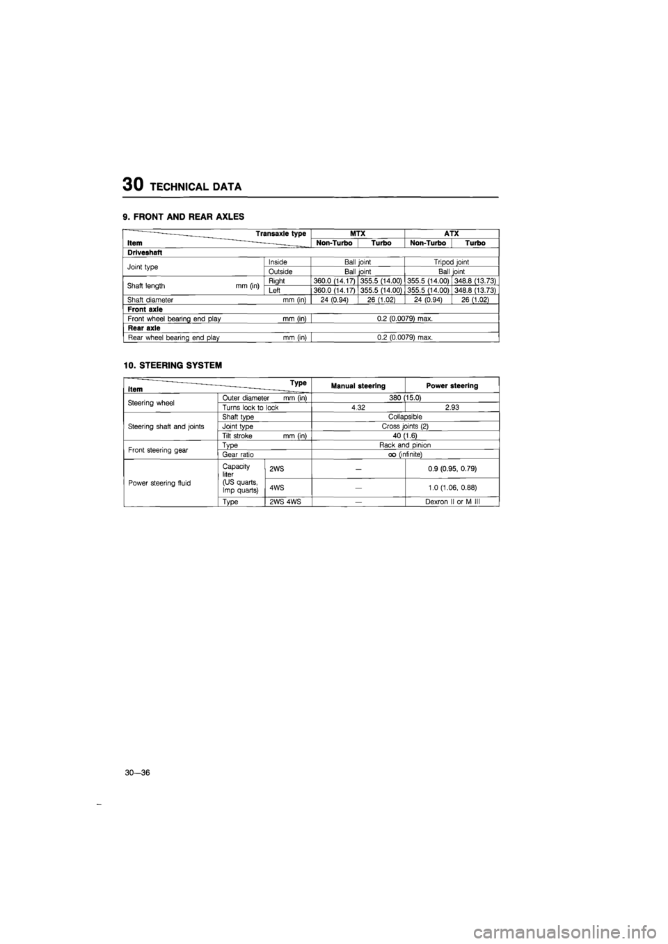
9. FRONT AND REAR AXLES
Transaxle type MTX ATX
Item Non-Turbo Turbo Non-Turbo Turbo
Driveshaft
Joint type Inside Ball joint Tripod joint Joint type Outside Ball joint Ball joint
Shaft length mm (in) Right 360.0 (14.17) 355.5 (14.00) 355.5 (14.00) 348.8 (13.73) Shaft length mm (in) Left 360.0 (14.17) 355.5 (14.00) 355.5 (14.00) 348.8 (13.73)
Shaft diameter mm (in) 24 (0.94) 26 (1.02) 24 (0.94) 26 (1.02)
Front axle
Front wheel bearing end play mm (in) 0.2 (0.0079) max.
Rear axle
Rear wheel bearing end play mm (in) 0.2 (0.0079) max.
10. STEERING SYSTEM
u _ Type Item ——- - -. Manual steering Power steering
Steering wheel Outer diameter mm (in) 380 15.0) Steering wheel Turns lock
to
lock 4.32 2.93
Steering shaft and joints
Shaft type Collapsible
Steering shaft and joints Joint type Cross joints
(2)
Steering shaft and joints
Tilt stroke mm (in) 40 (1.6)
Front steering gear Type Rack and pinion Front steering gear Gear ratio
oo
(infinite)
Power steering fluid
Capacity liter
(US quarts, Imp quarts)
2WS
—
0.9 (0.95, 0.79)
Power steering fluid
Capacity liter
(US quarts, Imp quarts) 4WS
—
1.0 (1.06, 0.88) Power steering fluid
Type 2WS 4WS
—
Dexron
II or M III
30—36
Page 1851 of 1865
TECHNICAL DATA 30
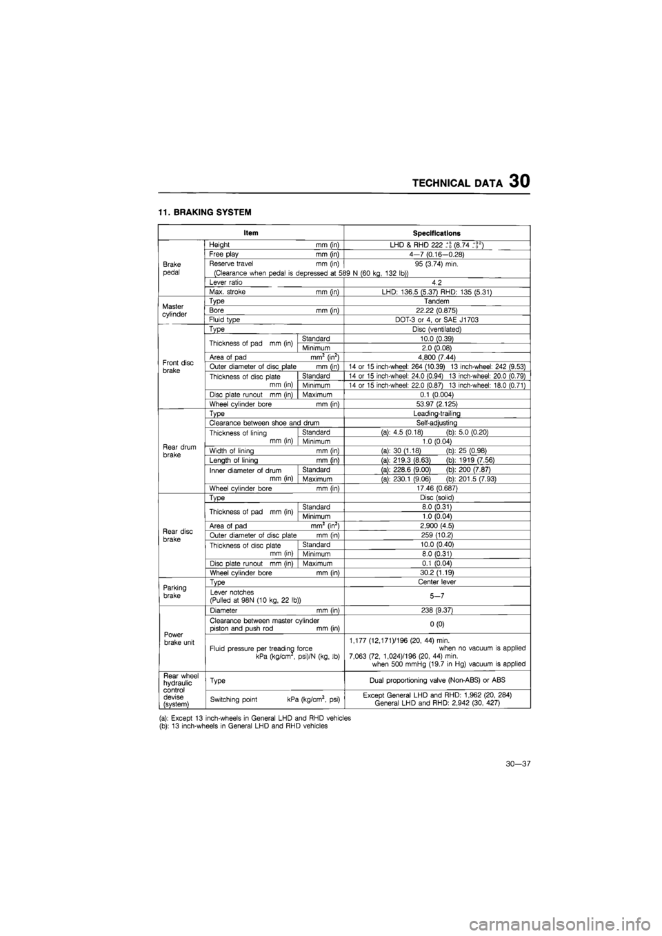
11. BRAKING SYSTEM
Item Specifications
Brake
pedal
Height
mm
(in) LHD
&
RHD 222 (8.74 _+g2)
Brake
pedal
Free play
mm
(in) 4-7 (0.16—0.28)
Brake
pedal
Reserve travel
mm (in)
(Clearance when pedal
is
depressed
at 5S
95 (3.74) min.
39
N
(60 kg, 132 lb))
Brake
pedal
Lever ratio 4.2
Brake
pedal
Max. stroke
mm (in)
LHD: 136.5 (5.37) RHD: 135 (5.31)
Master cylinder
Type Tandem Master cylinder Bore
mm
(in) 22.22 (0.875) Master cylinder Fluid type DOT-3
or 4, or
SAE J1703
Front disc brake
Type Disc (ventilated)
Front disc brake
Thickness
of
pad
mm (in)
Standard 10.0 (0.39)
Front disc brake
Thickness
of
pad
mm (in)
Minimum 2.0 (0.08)
Front disc brake
Area
of
pad mm2 (in2) 4,800 (7.44) Front disc brake Outer diameter
of
disc plate
mm (in)
14
or 15
inch-wheel: 264 (10.39)
13
inch-wheel: 242 (9.53) Front disc brake Thickness
of
disc plate
mm (in)
Standard 14
or 15
inch-wheel: 24.0 (0.94)
13
inch-wheel: 20.0 (0.79)
Front disc brake Thickness
of
disc plate
mm (in) Minimum 14
or 15
inch-wheel: 22.0 (0.87)
13
inch-wheel: 18.0 (0.71)
Front disc brake
Disc plate runout
mm (in)
Maximum 0.1 (0.004)
Front disc brake
Wheel cylinder bore
mm (in)
53.97 (2.125)
Rear drum
brake
Type Leading-trailing
Rear drum
brake
Clearance between shoe and drum Self-adjusting
Rear drum
brake
Thickness
of
lining mm (in)
Standard (a):
4.5
(0.18) (b): 5.0 (0.20)
Rear drum
brake
Thickness
of
lining mm (in) Minimum 1.0 (0.04) Rear drum
brake Width
of
lining
mm (in)
(a):
30
(1.18)
(b)
25 (0.98) Rear drum
brake Length
of
lining
mm fin)
(a): 219.3 (8.63)
(b)
1919 (7.56)
Rear drum
brake
Inner diameter
of
drum mm (in)
Standard (a): 228.6 (9.00)
(b)
200 (7.87)
Rear drum
brake
Inner diameter
of
drum mm (in) Maximum (a): 230.1 (9.06)
(b)
201.5 (7.93)
Rear drum
brake
Wheel cylinder bore
mm (in)
17.46 (0.687)
Rear disc
brake
TvDe Disc (solid)
Rear disc
brake
Thickness
of
pad
mm (in)
Standard 8.0 (0.31)
Rear disc
brake
Thickness
of
pad
mm (in)
Minimum 1.0 (0.04)
Rear disc
brake
Area
of
pad mm2 (in2) 2,900 (4.5) Rear disc
brake Outer diameter
of
disc plate
mm (in)
259 (10.2) Rear disc
brake Thickness
of
disc plate mm (in)
Standard 10.0 (0.40)
Rear disc
brake Thickness
of
disc plate mm (in) Minimum 8.0 (0.31)
Rear disc
brake
Disc
Dlate runout mm fin)
Maximum 0.1 (0.04)
Rear disc
brake
Wheel cylinder bore
mm (in)
30.2 (1.19)
Parking
brake
TvDe Center lever Parking
brake Lever notches
(Pulled
at
98N
(10
kg,
22 lb))
5-7
Power
brake unit
Diameter
mm (in)
238 (9.37)
Power
brake unit
Clearance between master cylinder piston and push
rod mm
(in) 0(0)
Power
brake unit Fluid pressure per treading force
kPa (kg/cm
,
psi)/N (kg,
lb)
1,177 (12,171 )/196 (20,
44)
min. when
no
vacuum
is
applied 7,063 (72, 1,024)/196 (20,
44)
min.
when 500 mmHg (19.7
in
Hg) vacuum
is
applied
Rear wheel hydraulic control devise (svstem)
Type Dual proportioning valve (Non-ABS)
or
ABS Rear wheel hydraulic control devise (svstem) Switching point kPa (kg/cm2,
psi)
Except General LHD and RHD: 1,962 (20, 284) General LHD and RHD: 2,942 (30, 427)
(a): Except
13
inch-wheels
in
General LHD and RHD vehicles (b):
13
inch-wheels
in
General LHD and RHD vehicles
30—37
Page 1852 of 1865
30 TECHNICAL DATA
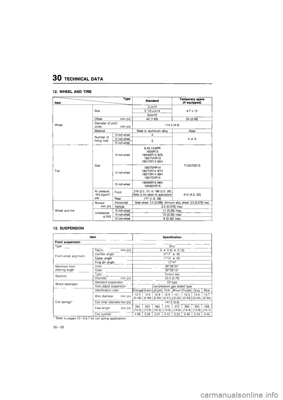
12. WHEEL AND TIRE
* ~— - Type
Item ~ ———_____ Standard Temporary spare
(if equipped)
Wheel
Size
5-Jx13
4-T
x 15
Wheel
Size 5 1/2-JJx14 4-T
x 15
Wheel
Size
6JJx15
4-T
x 15
Wheel
Offset
mm (in)
42 (1.65) 53 (2.09)
Wheel Diameter
of
pitch circle
mm
(in) 114.3 (4.5) Wheel
Material Steel
or
aluminum alloy Steel
Wheel
Number
of
fixing nuts
13 inch-wheel 4
4
or 5
Wheel
Number
of
fixing nuts 14 inch-wheel 5 4
or 5
Wheel
Number
of
fixing nuts 15 inch-wheel 5 4
or 5
Tire
Size
13 inch-wheel
6.45-13-6PR 165SR13 165/80R13 82S
185/70HR13 185/70R13 85H
T125/70D15
Tire
Size
14 inch-wheel
185/70HR14 185/70R14 87H 185/70R14 88H 185/70VR14
T125/70D15
Tire
Size
15 inch-wheel 195/60R15 86H 195/60VR15
T125/70D15
Tire
Air pressure kPa (kg/cm2, psi)
Front 216 (2.2, 31)
or
196 (2.0, 28)
Refer to tire labels for applications 412 (4.2, 60)
Tire
Air pressure kPa (kg/cm2, psi) Rear 177 (1.8,
26)
412 (4.2, 60)
Wheel and tire
Runout
mm (in)
Horizontal Steel wheel: 2.5 (0.098), Alminum allov wheel: 2.0 (0.079) max.
Wheel and tire
Runout
mm (in) Vertical 2.0 (0.079) max.
Wheel and tire Unbalance
g
(oz)
13 inch-wheel 11 (0.39) max. Wheel and tire Unbalance
g
(oz) 14 inch-wheel 10 (0.35) max.
Wheel and tire Unbalance
g
(oz) 15 inch-wheel 9 (0.32) max.
13. SUSPENSION
Item Specification
Front suspension
Type Strut
Toe-in
mm
(in) 0 ±
3 (0
±
0
12)
Front wheel alignment Camber angle 0°17' ±
45'
Front wheel alignment Caster angle 1 °13' ±
45'
King pin angle 12C 47'
Maximum front Inner 36°26'33"
steering angle Outer 30°59'15"
Stabilizer Type Torsion
bar
Stabilizer Diameter
mm (in)
20.0 (0.79)
Shock absorbers Standard suspension Oil type Shock absorbers Auto adjust suspension Low-pressure gas sealed type
Identification color Orange Green Light green Pink Brown Purple Gray Blue
Wire diameter
mm (in)
12.5
(0.49)
12.6
(0.49) 12.8 (0.50) 12.9 (0.51) 13.1 (0.52) 13.3 (0.53) 13.6 (0.54) 13.7 (0.54)
Coil springs* Coil inner diameter mm (in) 147.5 (5.8)
Free length
mm
(in) 344 (13.5)
CO <35
362
(14.3)
370
(14.6)
372 (14.6) 365 (14.4) 350 (13.8) 358 (14.1)
Coil number 4.99 5.09 5.31 5.42 5.53 5.46 5.34 5.45
* Refer
to
pages 13—5,6,7
for
coil spring applications
30-38
Page 1853 of 1865
TECHNICAL DATA 30
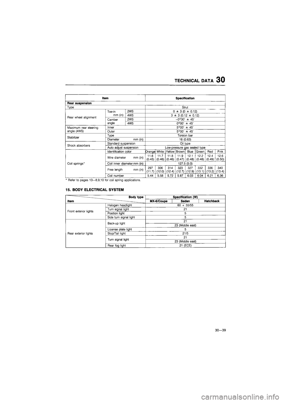
Item Specification
Rear suspension
Type Strut
Rear wheel alignment
Toe-in
mm (in)
2WS 0
± 3 (0 ±
0.12)
Rear wheel alignment
Toe-in
mm (in) 4WS 3
± 3
(0.12
±
0.12) Rear wheel alignment Camber angle
2WS -0°30'
± 45'
Rear wheel alignment Camber angle 4WS 0°00'
± 45'
Maximum rear steering angle (4WS)
Inner 5°00'
± 45'
Maximum rear steering angle (4WS) Outer 5°00'
± 45'
Stabilizer Type Torsion
bar
Stabilizer Diameter
mm
(in) 16 (0.63)
Shock absorbers Standard suspension Oil type Shock absorbers Auto adjust suspension Low-pressure
c
as sealed type
Coil springs*
Identification color Orange White Yellow Brown Blue Green Red Pink
Coil springs*
Wire diameter
mm (in)
11.6 (0.45)
11.7
(0.46)
11.8
(0.46) 11.9
(0.47)
12.1
(0.48)
12.2
(0.48)
12.4
(0.49)
12.6
(0.50)
Coil springs* Coil inner diameter mm (in) 127.5 (5.0) Coil springs*
Free length mm (in) 297 (11.7) 306 (12.0)
314
(12.4) 323 (12.7)
327 (12.9) 332
(13.1)
336
(13.2)
340
(13.4)
Coil springs*
Coil number 5.44 5.58 5.72 5.87 6.03 6.04 6.21 6.36
* Refer
to
pages 13—8,9,10
for
coil spring applications.
15. BODY ELECTRICAL SYSTEM
-—— Body type
Item ~ - -.
Specification (W) -—— Body type
Item ~ - -. MX-6/CouDe Sedan Hatchback
Front exterior lights
Haloaen headliaht 60
+
55/55
Front exterior lights Turn sianal liaht 21 Front exterior lights Position light 5 Front exterior lights
Side turn sianal liaht 5
Rear exterior lights
Back-up light 21
Rear exterior lights
Back-up light 23 (Middle east)
Rear exterior lights
License
Dlate
liaht 5
Rear exterior lights Stop/Tail light 21/5 Rear exterior lights
Turn signal light 21
Rear exterior lights
Turn signal light 23 (Middle east)
Rear exterior lights
Rear foa liaht 21 (ECE)
30—39
Page 1861 of 1865
SPECIAL TOOLS 40
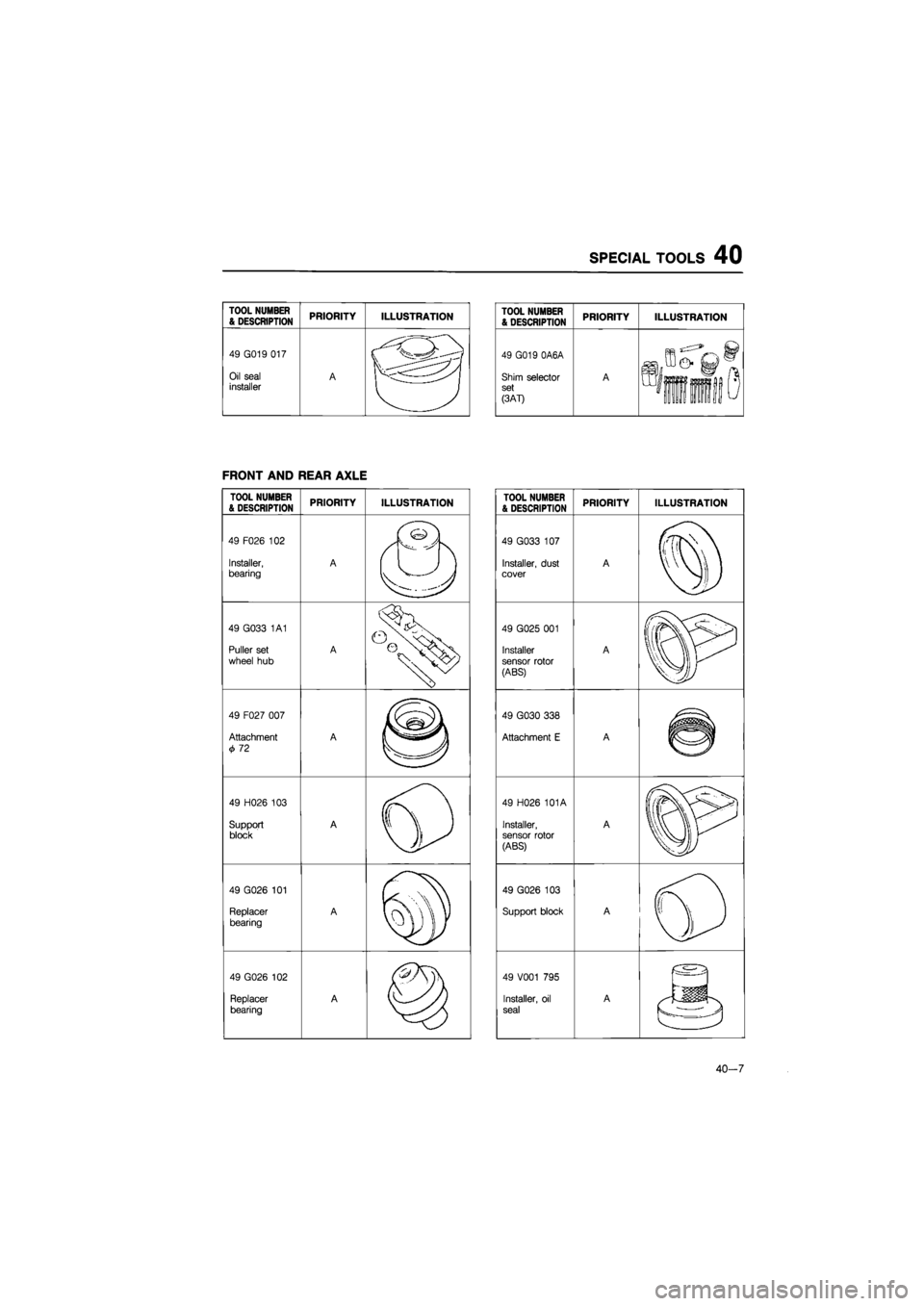
TOOL NUMBER
& DESCRIPTION PRIORITY ILLUSTRATION
49 G019 017
Oil seal installer A
FRONT AND REAR AXLE
TOOL NUMBER & DESCRIPTION PRIORITY ILLUSTRATION
49 F026
102
Installer, bearing A
49 G033
1A1
Puller set
wheel
hub
A
49 F027 007
Attachment
72
A
©
49 H026
103
Support block A
Q
49 G026
101
Replacer
bearing
A
%
49 G026
102
Replacer bearing A
TOOL NUMBER & DESCRIPTION PRIORITY ILLUSTRATION
49 G019 0A6A
Shim selector set
PAT)
A
%&iiS
TOOL NUMBER & DESCRIPTION PRIORITY ILLUSTRATION
49 G033
107
Installer, dust cover A
49 G025
001
Installer
sensor rotor
(ABS)
A
fP
49 G030 338
Attachment
E
A
©
49 H026 101A
Installer, sensor rotor (ABS)
A
IP
49 G026
103
Support block A
©
49 V001
795
Installer,
oil
seal
A
A
40-7