Page 434 of 1865
IDLE-UP CONTROL SYSTEM 4A
DUAL-SERVO DIAPHRAGM TYPE
With P/S and A/C
Solenoid valve (for P/S)
69G04B-124
Operation
A/C ON and compressor operating
Current flows through the A/C relay to the two-way solenoid valve for the A/C. Vacuum port A is opened,
and vacuum is applied to the servo diaphragm, which in turn pulls the throttle plates slightly open
at low speeds.
P/S operating
Current flows through the P/S switch to the three-way solenoid valve for power steering. Vacuum port
B is opened and vacuum is applied to the servo diaphragm, which in turn pulls the throttle plates slightly
open.
Relationship
Equipment
Type P/S A/C P/S & A/C
Single-servo
diaphragm type O O
Dual-servo
diaphragm type O
4A—69
Page 439 of 1865
![MAZDA 626 1987 Workshop Manual
4A IDLE-UP CONTROL SYSTEM
76G04A-144
76G04A-145
76G04A-146
Vacuum Signal [Equipped with A/C, only FE and
F8 (Except Middle East and General)]
1. Start the engine and run it at idle.
2. Disconn MAZDA 626 1987 Workshop Manual
4A IDLE-UP CONTROL SYSTEM
76G04A-144
76G04A-145
76G04A-146
Vacuum Signal [Equipped with A/C, only FE and
F8 (Except Middle East and General)]
1. Start the engine and run it at idle.
2. Disconn](/manual-img/28/57059/w960_57059-438.png)
4A IDLE-UP CONTROL SYSTEM
76G04A-144
76G04A-145
76G04A-146
Vacuum Signal [Equipped with A/C, only FE and
F8 (Except Middle East and General)]
1. Start the engine and run it at idle.
2. Disconnect the vacuum hose from the servo di-
aphragm.
3. Place a finger over the hose.
4. Increase the engine speed, and check for vacuum.
Engine model Engine speed Vacuum
pj| (Except Middle) Below 2,300 rpm Yes pj| (Except Middle) Above 2,300 rpm No
FE (Unleaded fuel) Below 1,500 rpm Yes FE (Unleaded fuel) Above 1,500 rpm No
F6 (Singapore) Below 2,100 rpm Yes F6 (Singapore) Above 2,100 rpm No
General and Middle East
1. Start the engine and run it at idle.
2. Disconnect the vacuum hose from the servo di-
aphragm.
3. Place a finger over the hose.
4. Operate the A/C or P/S.
5. Check that vacuum is felt.
P/S Switch
1. Start the engine and run it at idle.
2. Disconnect the power steering switch connector.
3. Connect an ohmmeter to the power steering
switch.
4. Turn the steering wheel all the way to either the
right or left, and check for continuity.
P/S Continuity
Operated Yes
Not operated No
5. Replace if necessary.
Solenoid Valve (A/C)
1. Disconnect vacuum hose A from the servo di-
aphragm.
2. Disconnect vacuum hose B from the solenoid
valve.
3. Disconnect the solenoid valve connector.
4. Blow air through the valve from hose A and check
that it comes out of port C.
76G04A-147
4A-74
Page 608 of 1865

ISC SYSTEM 4C
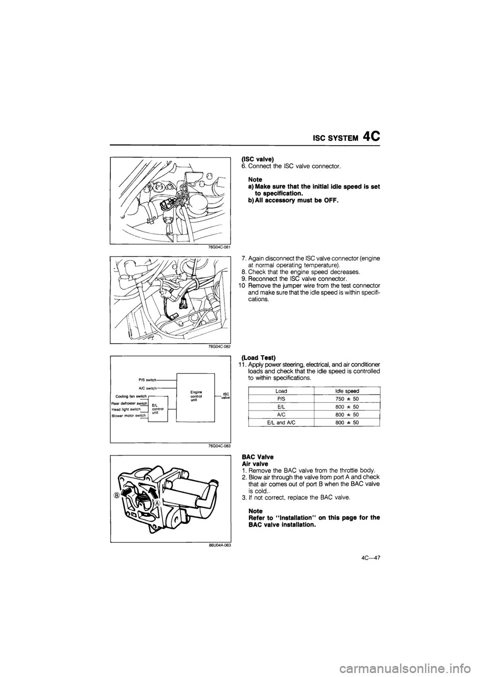
76G04C-081
76G04C-082
Cooling fan switch
Rear defroster switch
Head light switch
Blower motor switch
ISC "valve
76G04C-083
(ISC valve)
6. Connect the ISC valve connector.
Note
a) Make sure that the initial idle speed is set
to specification.
b) All accessory must be OFF.
7. Again disconnect the ISC valve connector (engine
at normal operating temperature).
8. Check that the engine speed decreases.
9. Reconnect the ISC valve connector.
10 Remove the jumper wire from the test connector
and make sure that the idle speed is within specifi-
cations.
(Load Test)
11. Apply power steering, electrical, and air conditioner
loads and check that the idle speed is controlled
to within specifications.
Load Idle speed
P/S 750 ± 50
E/L 800 ± 50
A/C 800 ± 50
E/L and A/C 800 ± 50
BAC Valve
Air valve
1. Remove the BAC valve from the throttle body.
2. Blow air through the valve from port A and check
that air comes out of port B when the BAC valve
is cold..
3. If not correct, replace the BAC valve.
Note
Refer to "Installation" on this page for the
BAC valve installation.
86U04A-063
4C—47
Page 819 of 1865
REMOVAL 7A
RF-N and RF-CX
1. Battery
2. Air cleaner assembly
3. Vacuum hose
4. Intercooler pipe and hose
(RF-CX)
5. Electric fan
6. Speedometer cable
7. Ground(s)
8. Clutch release cylinder
9. Pressure and return hoses
(power steering)
10. Starter
11. Wheel
12. Splash shield
13. Stabilizer
14. Joint shaft
15. Extension bar
16. Control rod
76G07A-011
17. Exhaust pipe bracket
18. Water pipe
19. Gusset plate (rear)
20. Gusset plate (front)
21. Under cover
22. Engine mount No.4
23. Engine mount No.2
24. Crossmember
7 A—13
Page 1289 of 1865

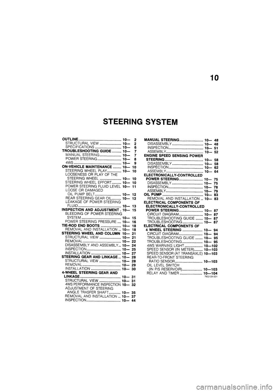
10
STEERING SYSTEM
OUTLINE 10— 2
STRUCTURAL VIEW 10— 2 SPECIFICATIONS 10— 6
TROUBLESHOOTING GUIDE 10— 7
MANUAL STEERING 10— 7
POWER STEERING 10— 8
4WS 10— 9
ON-VEHICLE MAINTENANCE 10— 10
STEERING WHEEL PLAY 10— 10
LOOSENESS OR PLAY OF THE
STEERING WHEEL 10— 10
STEERING WHEEL EFFORT 10— 10
POWER STEERING FLUID LEVEL 1 fl-11
LOOSE OR DAMAGED
OIL PUMP BELT IC— 12
REAR STEERING GEAR OIL 10— 12 LEAKAGE OF POWER STEERING
FLUID 10— 13
INSPECTION AND ADJUSTMENT. 10— 15
BLEEDING OF POWER STEERING
SYSTEM 10— 15
POWER STEERING PRESSURE ... 10— 16
TIE-ROD END BOOTS 10— 18
REMOVAL AND INSTALLATION .. 10— 18
STEERING WHEEL AND COLUMN 10— 21
STRUCTURAL VIEW 10— 21
REMOVAL 10— 22
DISASSEMBLY AND ASSEMBLY.. 10— 24
INSPECTION 10— 25
INSTALLATION 1 fl-27
STEERING GEAR AND LINKAGE .. IC— 28
STRUCTURAL VIEW 10— 28
REMOVAL 10— 29
INSTALLATION 10— 30
4-WHEEL STEERING GEAR AND
LINKAGE 10— 31
STRUCTURAL VIEW 10— 31 4WS PERFORMANCE INSPECTION 10— 32
ADJUSTMENT OF STEERING
ANGLE TRASFER SHAFT 10— 35
REMOVAL AND INSTALLATION .. 10— 37
INSPECTION 10— 44
MANUAL STEERING 10— 48
DISASSEMBLY 10— 48
INSPECTION 10— 51
ASSEMBLY 10— 52
ENGINE SPEED SENSING POWER
STEERING 10— 58
DISASSEMBLY 10— 58
INSPECTION 10— 62
ASSEMBLY 10— 64
ELECTRONICALLY-CONTROLLED
POWER STEERING 10— 75
DISASSEMBLY 10— 75
INSPECTION 10— 78
ASSEMBLY 10— 79
OIL PUMP 10— 83
REMOVAL AND INSTALLATION .. 10— 83
ELECTRICAL COMPONENTS OF
ELECTRONICALLY-CONTROLLED
POWER STEERING 10— 87
CIRCUIT DIAGRAM 10— 87
TROUBLESHOOTING GUIDE 10— 87
TROUBLESHOOTING 10— 87
ELECTRICAL COMPONENTS OF
4 WHEEL STEERING 10— 94
CIRCUIT DIAGRAM 10— 94
TROUBLESHOOTING GUIDE 10— 95
TROUBLESHOOTING 10— 95
4WS WARNING LIGHT 10—102
SPEED SENSOR (IN METER) 10—103
SPEED SENSOR (AT TRANSAXLE) 10—103
REAR-TO-FRONT STEERING
RATIO SENSOR 10—103
OIL LEVEL SWITCH
(IN P/S RESERVOIR) 10—103
RELAY AND TIMER 10—104 76G10X-001
Page 1291 of 1865
OUTLINE 10
1. Steering wheel
2. Steering shaft
3. Intermediate shaft
4. Steering gear assembly
5. Pressure hose
6. Return hose
7. Oil pump
8. Reserve tank
86U10X-003
Note
Engine speed sensing power steering is abbreviated ESPS.
10—3
Page 1292 of 1865
10 OUTLINE
86U10X-004
1. Steering wheel
2. Steering shaft
3. Intermediate shaft
4. Steering gear assembly
5. Pressure hose
6. Return hose
7. Oil pump
8. Solenoid valve
9. Control unit
10. Reserve tank
11. Steering angle sensor
12. Check connector
Note
Electronically - controlled power steering is abbreviated ECPS.
10—4
Page 1294 of 1865
10 OUTLINE
SPECIFICATIONS
—-———Type
Item ^— Manual steering Power steering
Steering wheel
Outer diameter
mm (in)
380 (15.0) Steering wheel Turns lock
to
lock 4 32 2.93
Steering shaft and joints
Shaft type Collapsible
Steering shaft and joints Joint type Cross joints
(2)
Steering shaft and joints
Tilt stroke
mm (in)
40 (1.6)
Front steering gear
Type Rack and pinion
Front steering gear Gear ratio
oo
(infinite)
Power steering fluid
Capacity liter (US qt, Imp)
2WS
—
0.9 (0.95, 0.79)
Power steering fluid
Capacity liter (US qt, Imp) 4WS
—
1.0 (1.06, 0.88) Power steering fluid
Type 2WS
4WS
—
Dexron
II or M III
86U10X-006
Note
2-Wheel steering is abbreviated 2WS.
10—6