Page 9 of 25
 the
bulb failure monitor, are located behind the
glovebox on models up to 1987.
2On models from 1987, the control and bulb
failure modules are located")
Location
1The AWS control unit, and (when fitted) the
bulb failure monitor, are located behind the
glovebox on models up to 1987.
2On models from 1987, the control and bulb
failure modules are located behind the driver’s
side footwell trim panel.
Testing
3Thorough testing and fault finding should
be left to a Ford dealer or other electrical
specialist, having test equipment. Unskilled or
uninformed testing may cause damage.
4Investigation of malfunctions should begin
by checking that all wiring is intact and
securely connected. If checking wires or
sensors for continuity, always disconnect the
control unit and/or bulb failure monitor before
so doing, otherwise damage may be caused.
5Note that false oil level readings can result if
the car is parked on a slope. False bulb failure
warnings may occur if incorrect wattage bulbs
are fitted.
Removal and refitting
6Disconnect the battery negative lead.
Warning lamp bulbs
7Remove the single screw from the top edge
of the facia panel in which the warning lamps
are housed, then withdraw the facia panel
(see illustration).
8Twist the relevant bulbholder through 90º to
remove it from the rear of the facia panel. The
bulb is integral with the bulbholder and must
be renewed as a unit (see illustration).
9Refitting is a reversal of removal.
Graphic display unit and bulbs
10Remove the clock or trip computer.
11Remove the display unit retaining screw
and the retainer, then pull the unit forwards
and disconnect the wiring plug using a thin-
bladed screwdriver (see illustrations).
12To renew a bulb, remove the two securing
screws and pull the circuit board from the
back of the unit to reveal the bulbs. The bulbs
are a push-fit.
13Refitting is a reversal of removal.
Control unit and bulb failure monitor
14Unclip the trim panel from the lower edge
of the passenger side lower facia panel.
15On models up to 1987, pull off the two
clips to release the control unit/bulb failure
monitor mounting bracket. Depress the
retaining tab and disconnect the relevant
wiring plug, then remove the two securing
screws and withdraw the control unit/bulb
failure monitor (see illustration).
16On models from 1987, release the
retaining tang and carefully slide the control
unit/bulb failure monitor downwards. Depress
the retaining tab and disconnect the relevant
wiring plug, then withdraw the control
unit/bulb failure monitor.
17Refitting is a reversal of removal. Note
that when both a control unit and bulb failure
monitor are fitted, the control unit wiring plug
is coloured brown, and the bulb failure
monitor wiring plug is coloured green.
Ice warning sender
18This sender is located beneath the front
panel on the right-hand side of the vehicle.
19Where necessary, for improved access
remove the horn.
20Depress the two retaining tangs,
disconnect the wiring plug and withdraw the
sender unit from the slot in the front panel.
21Refitting is a reversal of removal.
Door/tailgate/boot lid ajar switches
22Remove the relevant lock.
23Pull the switch from its location in the lock
body, disconnect the wiring plug (if not
already done) and withdraw the switch (see
illustration).24Refitting is a reversal of removal.
Low coolant level sensor
25Refer to Chapter 3.
Low washer fluid level switch
26Syphon out the contents of the reservoir,
then prise the switch from its grommet using a
thin-bladed screwdriver. Disconnect the
wiring plug.
27Refitting is a reversal of removal, using a
new grommet if necessary. Use a little liquid
detergent as a lubricant.
28On completion, refill the reservoir.
Low fuel level switch
29The switch is integral with the fuel level
sender unit. Details of fuel level sender unit
removal and refitting are given in Chapter 4.
Low oil level switch
30The switch is integral with the oil level
dipstick. To remove, simply withdraw the
23Auxiliary warning system
components - location,
testing, removal and refitting
Body electrical system 13•9
13
23.11a Removing the graphic display unit
retaining screw
23.23 Door lock and door ajar switch23.15 Auxiliary warning system control unit
location
23.11b Disconnecting the wiring plug from
the graphic display unit
23.8 Removing an auxiliary warning lamp
bulb23.7 Remove the screw from the warning
lamp facia panel
Page 10 of 25

dipstick from its tube and disconnect the
wiring plug.
31Refitting is a reversal of removal.
1Remove the instrument panel.
2Unclip the direction indicator relay from the
steering column support bracket (see
illustration).
3Unclip the “lights-on” warning module from
the steering column support bracket,
disconnect the wiring plug and remove the
module.
4Refitting is a reversal of removal.
1Disconnect the battery negative lead.
2To remove a lamp, simply prise it from its
location, using a thin-bladed screwdriver, and
disconnect the wiring (see illustrations).
When working on an overhead console-
mounted courtesy lamp, disconnect the
wiring between the map reading lamps and
the courtesy lamp before removing the
courtesy lamp.
3Refitting is a reversal of removal.1Disconnect the battery negative lead.
2Remove the courtesy lamp and disconnect
the map reading lamp wires.
3Push the map reading lamp out of its
location by inserting a finger through the
courtesy lamp aperture.
4Refitting is a reversal of removal.
1Disconnect the battery negative lead.
Courtesy lamp
2Remove the courtesy lamp.
3Unclip the bulb from the lamp. On models
fitted with an overhead console and map
reading lamps, the courtesy lamp reflector
must be unclipped for access to the bulb (see
illustration).
4Refitting is a reversal of removal.
Map reading lamp
5Remove the map reading lamp.
6Pull the bulbholder from the rear of the
lamp. The bulb is a push fit in the bulbholder
(see illustration).
7Refitting is a reversal of removal.
Glove compartment lamp
8Open the glove compartment and pull the
bulb from its holder.
9Refitting is a reversal of removal.
Ashtray lamp
10Open the ashtray and remove the tray
from its housing.
11Pull the bulbholder from the housing. The
bulb is a push fit in the bulbholder.
12Refitting is a reversal of removal.
Heater blower switch illumination
lamp
13Carefully pull off the switch knob, using
pliers with padded jaws if necessary. The bulb
is a bayonet fit in the end of the switch shaft.
14Refitting is a reversal of removal.
Heater control illumination lamp
15Refer to Chapter 12.
Vanity mirror illumination lamp
16Lower the sun visor and, using a thin-
bladed screwdriver, prise out the mirror and
diffuser assembly. Remove the festoon bulb(s)
from its/their spring contacts.
17Refitting is a reversal of removal.
Hazard flasher switch lamp
18Remove the securing screws and unclip
the upper steering column shroud.
19Ensure that the switch is in the “on”
position, then pull off the switch cap/bulb
cover. Carefully pull the bulb from the switch
using a pair of pliers with padded jaws.
20Refitting is a reversal of removal.
Automatic transmission gear
selector illumination lamp
21Unscrew the selector lever handle from
the threaded end of the lever, then remove the
three securing screws and withdraw the
centre console front upper panel.
22Pull of the selector gate cover to expose
the bulbholder. The bulb is a bayonet fit in the
bulbholder.
23Refitting is a reversal of removal.
Luggage compartment lamp
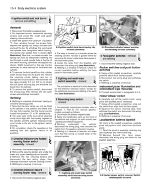
24Remove the lamp by carefully prising it
from its location using a thin-bladed
screwdriver. Unclip and remove the bulb (see
illustration).
25Refitting is a reversal of removal.
27Interior lamp bulbs - renewal
26Map reading lamp - removal
and refitting
25Courtesy lamp and luggage
compartment lamp - renewal
24“Lights-on” warning module
- renewal
13•10Body electrical system
24.2 “Lights-on” warning module location
A “Lights-on” warning module
B Direction indicator relay
C “Lights-on” warning module wiring plug
25.2b Removing a luggage compartment
lamp
27.6 Removing a map reading lamp bulb27.3 Overhead console-mounted courtesy
lamp bulb (arrowed)
25.2a Removing a courtesy lamp
Page 11 of 25

Clock illumination lamp
26Remove the clock.
27The bulb is a bayonet fit in the rear of the
clock.
28Refitting is a reversal of removal.
1Disconnect the battery negative lead.
Removal and refitting
2Detach the wiring connector at the left-hand
bonnet hinge, and attach a length of string to
the end of the wire running from the lamp.
3If necessary, remove the underbonnet
insulation by prising out the two-piece plastic
securing clips, then working at the lamp, pull the
wiring and the string through the bonnet panel.
4Detach the string from the end of the wire,
and remove the screw securing the lamp to
the bonnet. Withdraw the lamp.
5Commence refitting by attaching the end of
the wiring to the string, and pulling the string
and wiring through the bonnet panel. Further
refitting is a reversal of removal.
Bulb renewal
6Simply press and twist the bulb to remove it
from the bulbholder (see illustration).
7Refitting is a reversal of removal.
Removal
1The horn(s) is/are located in front of the
radiator beneath the front panel (see
illustration). The horn(s) may be located on
either side of the vehicle depending on model.
2Disconnect the battery negative lead.
3Disconnect the wiring from the horn, then
unscrew the securing nut and washer and
withdraw the horn and bracket assembly
complete.
4Repeat the operations for the remaining
horn where applicable.
Refitting
5Refitting is a reversal of removal.
Removal
1On models fitted with a trip computer,
remove the speed sender unit.
2Remove the instrument panel.
3Pull the cable through the bulkhead into the
engine compartment, and where applicable
release it from the securing clips. On models
fitted with a trip computer, the upper section
of the cable can now be removed.
4Apply the handbrake, jack up the front of
the vehicle and support on axle stands (see
“Jacking and Vehicle Support”).
5On vehicles with a manual gearbox, extract
the circlip securing the cable end to the
extension housing and withdraw the cable
end (see illustration).
6On vehicles with automatic transmission,
remove the securing screw and disconnect
the cable end from the extension housing.
7The cable can now be withdrawn from the
vehicle, noting its routing so that it can be
refitted in the same position.
Refitting
8Refitting is a reversal of removal, but where
applicable, ensure that the speedometer
cable rubber sleeve is in place over the square
inner drive on the cable connector, and not in
the speedometer head. Position the cable so
that the coloured bands on the cable sheath
line up with the bulkhead grommet and the
clips in the engine compartment. Route the
cable as noted during removal.9On completion, pull the speedometer cable
from within the engine compartment to ensure
that the cable is straight between the
instrument panel and the bulkhead grommet.
1The wiper blades should be renewed when
they no longer clean the glass effectively.
2Lift the wiper arm away from the glass.
3With the blade at 90º to the arm, depress
the spring clip and slide the blade clear of the
hook, then slide the blade up off the arm.
4If necessary extract the two metal inserts
and unhook the wiper rubber.
5Fit the new rubber and blade in reverse
order, making sure where necessary that the
cut-outs in the metal inserts face each other.
Windscreen and rear wipers
1Lift the hinged covers and remove the nuts
and washers securing the arms to the spindles.
2Mark the arms and spindles in relation to each
other then prise off the arms using a screwdriver.
Take care not to damage the paintwork.
3Refitting is a reversal of removal.
Headlamp wipers
4The procedure is as described in
paragraphs 1 to 3, but the washer hose must
be disconnected from the nozzle on the wiper
arm (see illustration).
32Wiper arms - removal and
refitting
31Wiper blades - renewal
30Speedometer cable - removal
and refitting
29Horn - removal and refitting
28Underbonnet lamp - removal,
refitting and bulb renewal
Body electrical system 13•11
13
29.1 Horn location beneath front panel
30.5 Speedometer cable end fitting in
manual gearbox extension housing
28.6 Removing an underbonnet lamp bulb27.24 Removing a luggage compartment
lamp bulb
32.4 Removing a headlamp wiper arm
Page 12 of 25

Windscreen and rear window
washers
1To remove a nozzle, carefully prise it from
its location using a thin-bladed screwdriver.
Disconnect the washer hose and withdraw the
nozzle.
2To refit, reconnect the washer hose to the
nozzle, and push the nozzle into its locating
hole.
3The nozzles can be adjusted by inserting a
pin into the jet and swivelling to the required
position.
Headlamp washers
Models up to 1987
4Remove the radiator grille panel.
5Disconnect the washer hose from the
nozzle.
6Separate the upper and lower halves of the
nozzle by prising apart with a thin-bladed
screwdriver, then withdraw the nozzle halves.
7Refitting is a reversal of removal.
8The nozzles can be adjusted as described
in paragraph 3.
Models from 1987
9Disconnect the washer hose from the
nozzle on the end of the wiper arm.
10Prise the combined wiper blade mounting
and nozzle from the wiper arm using a thin-
bladed screwdriver or a pair of pliers.
11Refitting is a reversal of removal.
12Note that the nozzles are not adjustable.
Removal
1Disconnect the battery negative lead.
2Remove the wiper arms.
3Remove the windscreen cowl panel.
4Disconnect the wiring plug from the motor.
5Remove the seven securing screws, and
withdraw the mounting bracket together with
the linkage and motor (see illustration). 6Unscrew the nut securing the link arm to
the motor shaft, then remove the three
securing bolts, and withdraw the motor from
the mounting bracket.
Refitting
7Refitting is a reversal of removal.
Removal
1Where headlamp washers are fitted, a
separate pump is used. The pump(s) is/are a
push-fit in the base of the washer fluid
reservoir (see illustration).
2Disconnect the battery negative lead.
3To remove a pump, syphon out the
contents of the reservoir, then pull the pump
from its grommet.
4Disconnect the wiring plug and the washer
hose.
Refitting
5Refitting is a reversal of removal, using a
new grommet if necessary. Use a little liquid
detergent as a lubricant.
6On completion, refill the reservoir and
check for correct operation.
1Where headlamp washers are fitted, a
combined windscreen/headlamp washer fluid
reservoir is used. On models up to 1987, the
reservoir is mounted on the right-hand side of
the engine compartment. On models from
1987, the reservoir is mounted under the
right-hand front wing, but has a filler within
the engine compartment.
2Disconnect the battery negative lead.
Models up to 1987
3Syphon out the contents of the reservoir, and
disconnect the wiring plug(s) and washer hose(s).
4Remove the two or three reservoir retaining
screws, as applicable, then withdraw the
reservoir.5Refitting is a reversal of removal.
Models from 1987
6Proceed as described in paragraph 3.
7Working under the front wing, remove the
three reservoir securing screws and pull the
reservoir down slightly. On vehicles fitted with
front foglamps, the bumper must be removed.
8Withdraw the reservoir.
9Refitting is a reversal of removal.
Hatchback models
1Disconnect the battery negative lead.
2Remove the wiper arm.
3Open the tailgate; remove the trim panel.
4Unscrew the earth lead and disconnect the
wiring plug from the motor.
5Remove the three securing bolts and
withdraw the mounting bracket and motor
from the tailgate (see illustration).
6The motor can be separated from the
mounting bracket by removing the three
securing bolts.
7Refitting is a reversal of removal.
Estate models
8The procedure is as described for
Hatchback models except that the washer
hose must be disconnected from the motor
assembly, and the mounting bracket is
secured by four bolts.
The procedure is as described for the
windscreen/headlamp washer pump.
Removal
1On models from 1987, the rear window
washer circuit shares the same reservoir as
the windscreen/headlamp washers.
39Rear window washer fluid
reservoir - removal and
refitting
38Rear window washer pump -
removal and refitting
37Rear window wiper motor -
removal and refitting
36Windscreen/headlamp
washer fluid reservoir -
removal and refitting
35Windscreen/headlamp
washer pump - removal and
refitting
34Windscreen wiper motor and
linkage - removal and refitting
33Washer nozzles - removal and
refitting
13•12Body electrical system
35.1 Windscreen washer pump - models
from 198737.5 Rear window wiper motor location -
mounting bracket securing bolts arrowed34.5 Windscreen wiper motor bracket
securing screws (arrowed)
Page 13 of 25
. To remove the reservoir proceed
as follows.
3Disconnect the b")
2On models up to 1987, the reservoir is
located behind the trim panel on the left-hand
side of the luggage compartment (see
illustration). To remove the reservoir proceed
as follows.
3Disconnect the battery negative lead.
4Remove the trim panel.
5Operate the washers to reduce the fluid
level in the reservoir.
6Remove the reservoir filler cap, and
disconnect the wiring plug and water hose.
7Remove the two securing screws and
withdraw the reservoir.
Refitting
8Refitting is a reversal of removal.
Note: On vehicles fitted with foglamps, the
headlamp unit must be removed when the right-
hand headlamp wiper motor is to be removed.
Removal
1Disconnect the battery negative lead.
2Disconnect the washer hose from the
nozzle on the end of the wiper arm, then
remove the wiper arm.
3Pull the washer hose and retainer from the
end of the motor shaft.
4Remove the radiator grille panel.
5Where applicable, prise the trim strip from
the bottom of the headlamp unit for access to
the wiper motor mounting bolts (see
illustrations). 6Remove the two mounting bolts, then
working under the wheel arch, slide the wiper
motor rearwards, disconnect the wiring plug
and withdraw the motor.
Refitting
7Refitting is a reversal of removal, but on
completion adjust the free length of the
washer hose between the nozzle and the
retainer on the motor shaft.
1Disconnect the battery negative lead.
2Remove the radiator grille panel.
Models up to 1987
3Disconnect the headlamp wiring plug(s)
(see illustration).4Remove the three or four headlamp
securing bolts, as applicable, and the lower
sliding clamp bracket bolt on the rear of the
headlamp, then withdraw the headlamp (see
illustrations).
5If required, the headlamp lens can be
removed by releasing the spring clips around
its edge.
6Refitting is a reversal of removal, but the
headlamp securing bolts should not be
tightened until the headlamp is aligned with
the front grille panel.
7On completion, check the headlamp
alignment.
Models from 1987
8Disconnect the headlamp wiring plug(s)
(see illustration).
9Where applicable, remove the headlamp
wiper motor.
41Headlamp unit - removal and
refitting
40Headlamp wiper motor -
removal and refitting
Body electrical system 13•13
13
40.5b . . . for access to the headlamp wiper
motor mounting bolts
41.4d . . . then withdraw the headlamp unit
- models up to 198741.4c . . . and the lower sliding clamp
bracket bolt . . .41.4b . . . the rear securing bolt . . .
41.4a Remove the upper headlamp
securing bolts (arrowed) . . .41.3 Disconnect the headlamp wiring plug
- models up to 1987
40.5a Prise the trim strip from the bottom
of the headlamp unit . . .39.2 Rear window washer fluid reservoir
location - Hatchback models up to 1987.
Securing screws arrowed
Page 14 of 25
.
11Pull the headlamp forwards, then swivel it
an")
10Remove the headlamp securing bolt and
the two nuts, then release the anchor spring
and withdraw the direction indicator !amp unit
(see illustrations).
11Pull the headlamp forwards, then swivel it
and remove it sideways.
12If required, the headlamp lens can be
removed by releasing the spring clips around
its edge.
13Refitting is a reversal of removal.
14On completion, check the headlamp
alignment.
1It is recommended that the headlamp
alignment is carried out by a Ford dealer using
specialist beam setting equipment. However,
in an emergency the following procedure will
provide an acceptable light pattern.
2With the vehicle unladen, with a full tank of
fuel, and with the tyres correctly inflated,
position the vehicle approximately 10 metres(33 feet) in front of, and at right-angles to, a
wall or garage door.
3Draw a vertical line on the wall
corresponding to the centre line of the car.
The position of the line can be ascertained by
marking the centre of the front and rear
screens with crayon then viewing the wall
from the rear of the car.
4Complete the lines shown (see
illustration).
5Switch the headlamps on dipped beam and
adjust them as necessary using the knobs
located behind the headlamps (see
illustration). Cover the headlamp not being
checked with cloth.
1Disconnect the battery negative lead.
Saloon and Hatchback models
2Working inside the luggage compartment,
press the plastic retaining tab and remove thebulbholder assembly.
3Disconnect the wiring plug from the
bulbholder.
4Unscrew the securing nuts, and withdraw
the rear lamp unit from outside the vehicle.
Recover the gasket.
5Refitting is a reversal of removal.
Estate models
6Working inside the luggage compartment,
turn the retaining tabs a quarter-turn and
remove the rear side trim panel cover.
7Push out the retaining tabs and withdraw
the bulbholder.
8Disconnect the wiring plug from the
bulbholder.
9Unscrew the four securing nuts, and
withdraw the rear lamp unit from outside the
vehicle. Recover the gasket.
10Refitting is a reversal of removal.
43Rear lamp unit - removal and
refitting
42Headlamps - alignment
13•14Body electrical system
41.8 Disconnect the headlamp wiring plug
- models from 198741.10b . . . the upper securing nut . . .
42.5 Adjusting the headlamp alignment
42.4 Headlamp alignment chart
A Distance between headlamp centres
B Light/dark boundary
C Centre of dipped beam
D Dipped beam patternH Height of headlamp centre from ground
X = 160.0 mm (6.3 in) for all models up to 1987
120.0 mm (4.7 in) for all models from 1987
41.10c . . . and the side securing nut -
models from 1987
41.10a Remove the headlamp rear
securing bolt . . .
Page 15 of 25
.
12Working through the cargo area aperture,
unscrew the two wing nu")
P100 models
11Remove the two securing screws and
detach the rear lamp wiring cover from the
side of the cargo area(see illustration).
12Working through the cargo area aperture,
unscrew the two wing nuts and remove the
rear lamp cover.
13Disconnect the wiring plug from the back
of the lamp unit.
14Unscrew the four securing nuts and
withdraw the lamp unit from outside the cargo
area. Recover the gasket.
15Refitting is a reversal of removal, but
ensure that the plastic washer between the
wiring plug and the lamp unit is seated
correctly, and make sure that the wiring
protective sheath is seated correctly in the
opening in the lamp cover.
1Disconnect the battery negative lead.
Models up to 1987
Low specification
2Push the lamp unit rearwards into the
bumper until the plastic retaining tang is heard
to click in the locked position.
3Withdraw the lamp unit from the front of the
bumper and disconnect the wiring plug (see
illustration).
4Commence refitting by reconnecting the
wiring plug.
5Release the retaining tang, then refit the
lamp unit to the bumper, ensuring that the
pivot on the lamp unit engages with the slot in
the bumper. Reconnect the battery.
High specification
6Press the release lever at the top of the
lamp unit upwards, and withdraw the unit
from the bumper. Disconnect the wiring plug.
7To refit, reconnect the wiring plug, then
push the lamp unit into the bumper until it
locates securely. Reconnect the battery.
All models from 1987
8Working in the engine compartment,
unhook the lamp unit anchor spring from itsanchorage next to the headlamp, then
withdraw the lamp unit sideways from its
recess (see illustrations). Disconnect the
bulbholder by twisting it anti-clockwise.
9Refitting is a reversal of removal, but ensure
that the locating pins on the lamp unit engage
with the corresponding holes in the headlamp
mounting panel.
1Disconnect the battery negative lead.
Models up to 1987
2To improve access, turn the steering onto
full lock.
3Remove the relevant wheel arch liner.
4Working under the wheel arch, depress the
retaining tabs and withdraw the lamp through
the outside of the wing (see illustration).
Disconnect the bulbholder by twisting it anti-
clockwise.
5Refitting is a reversal of removal.
Models from 1987
6To improve access, turn the steering onto
full lock.
7Working in the engine compartment,
disconnect the wiring plug.
8Remove the relevant wheel arch liner.
9Working under the wheel arch, twist the
lamp clockwise and withdraw it through theoutside of the wing. Feed the wiring through
the holes in the wing panels.
10Refitting is a reversal of removal.
1Disconnect the battery negative lead.
Models up to 1987
2Remove the relevant front direction
indicator lamp unit.
3Release the retaining catch on the inside
edge of the lamp, then withdraw the lamp
from the bumper and disconnect the wiring
plug (see illustration).
4Refitting is a reversal of removal.
46Front foglamps - removal and
refitting
45Front direction indicator side
repeater lamp - removal and
refitting
44Front direction indicator
lamp unit - removal and
refitting
Body electrical system 13•15
13
44.8a Unhook the front direction indicator
lamp unit anchor spring . . .
46.3 Front foglamp removal -
models up to 1987
A Retaining catch45.4 Withdrawing a front direction
indicator side repeater lamp -
models up to 1987
44.8b . . . and withdraw the lamp unit
44.3 Withdrawing a front direction
indicator lamp unit - “low specification”
models up to 198743.11 Rear lamp wiring cover (A) and rear
lamp cover (B) - P100 models
Page 16 of 25

Models from 1987
5Remove the two securing screws, then
withdraw the lamp forwards and disconnect
the two wiring plugs.
6Refitting is a reversal of removal, but where
necessary use a new gasket between the
lamp and bumper.
7On completion, the vertical alignment of the
foglamp must be adjusted. For the foglamps,
dimension “X” (see illustration, 42.4) should
be taken as 220.0 mm (8.7 in). The adjuster
screw is located on the inside edge of the
lamp above the securing screw (see
illustration).
1Disconnect the battery negative lead.
Saloon, Hatchback and Estate
models
2To remove a lamp, simply prise it from the
bumper using a thin-bladed screwdriver, and
disconnect the wiring plug (see illustration).
3Refitting is a reversal of removal.
P100 models
4Working behind the rear crossmember, pull
the wiring plug from its clip and disconnect it.
5Pull the lamp cover from the rubber
housing, then pull the rubber housing and the
wiring from the crossmember.
6Refitting is a reversal of removal.
Note: The glass envelopes of the headlamp,
auxiliary driving lamp and front foglamp bulbs
must not be touched with the fingers. If the
glass is accidentally touched, it should be
washed with methylated spirits and dried with
a soft cloth. Failure to observe this procedure
may result in premature bulb failure.
1Disconnect the battery negative lead.
Headlamps
2Working in the engine compartment,
remove the headlamp rear cover by turning it
anti-clockwise (see illustration).3Pull the wiring plug from the base of the
bulb, then release the spring clip, grasp the
bulb by its contacts and carefully withdraw it
(see illustrations). Do not touch the bulb
glass.
4Refitting is a reversal of removal, but on
models up to 1987, refit the headlamp rear
cover by aligning the arrow on the cover with
the depression on the top of the headlamp
unit and turning the cover clockwise until the
arrow aligns with the lower depression. On
models from 1987, the word “OBEN “ or
“TOP” on the rear cover should be exactly at
the top after refitting.
Sidelamps
5Working in the engine compartment,
remove the headlamp rear cover by turning it
anti-clockwise.
6Pull the sidelamp bulbholder from its
location in the headlamp reflector (seeillustration). On “high specification” models
up to 1987 a retaining tab must be depressed
before withdrawing the bulbholder. Note that
the rubber sleeve should be left in position in
the reflector.
7Refitting is as described in paragraph 4.
Auxiliary driving lamps
Models up to 1987
8Twist the cover on the top of the headlamp
unit anti-clockwise and remove it to expose
the bulb (see illustration).
9Release the bulb from the two clips, then
disconnect the wiring and remove the bulb.
Do not touch the bulb glass (see illustration).
10Refitting is a reversal of removal.
Models from 1987
11Release the spring clip securing the cover
to the rear of the headlamp unit, then remove
the cover (see illustration).
48Exterior lamp bulbs - renewal
47Rear number plate lamp -
removal and refitting
13•16Body electrical system
46.7 Front foglamp adjuster screw (A) and
securing screws (B) - models from 1987
48.2 Remove the headlamp rear cover
48.8 Auxiliary drive lamp bulb cover
(arrowed) - models up to 198748.6 Removing a sidelamp bulbholder48.3b Release the spring clip and withdraw
the headlamp bulb
48.3a Pull off the wiring plug . . .
47.2 Removing a rear number plate lamp -
Saloon, Hatchback and Estate models