Page 352 of 3115

BE2F2-01
I20790
Key Plate Inserted
ON
OFFWithin. 5secs.
1 Key Plate Not Inserted
23 910Within. 30secs.
Once 9 times BE-100
- BODY ELECTRICALWIRELESS DOOR LOCK CONTROL SYSTEM
2473 Author�: Date�:
2004 LAND CRUISER (RM1071U)
INSPECTION
1. CHARACTERS OF WIRELESS DOOR LOCK
(a) The operation distance changes according to how cus-
tomers hold the transmitter or where it is used.
(b) Because of using the very weak radio wave, if there is a
strong wave or noise on the frequency being used, the op-
eration distance may become shorter.
2. WIRELESS DOOR LOCK BASIC FUNCTION
(a) Stand on the driver's side. Stay 1 m away from the ve-
hicle.
(b) Turn the transmitter toward the vehicle and press any one
of the transmission switched for 1 sec.
3. INSPECT WIRELESS DOOR LOCK DIAGNOSIS MODE
(a) Start up diagnosis mode.
HINT:
Follow the method below.
(1) Insert the ignition key into the ignition key cylinder.
(2) Remove the ignition key from the ignition key cylin-
der.
(3) Insert the key into the ignition switch.
(4) Turn the ignition switch ON once within 5 sec.
(5) Repeat turnning the ignition switch OFF " ON 9
times within 30 sec.
(6) Enter the diagnosis mode, and make sure that the
taillight lights up.
(b) Finishing the Diagnosis Mode.
During the Diagnosis mode, turn the ignition switch OFF
" ON to go back to the normal mode.
At this time make sure that the taillight lights up.
Page 357 of 3115
BE0CI-07
- BODY ELECTRICALWIRELESS DOOR LOCK CONTROL SYSTEM
BE-99
2472 Author�: Date�:
2004 LAND CRUISER (RM1071U)
PRE-CHECK
1. CHARACTERS OF WIRELESS DOOR LOCK
(a) The operation distance changes according to how customers hold the transmitter or where it is used.
(b) Because of using the very weak radio wave, if there is a strong wave or noise on the frequency being
used, the operation distance may become shorter.
2. WIRELESS DOOR LOCK BASIC FUNCTION
(a) Stand on the driver's side. Stay 1 m away from the vehicle.
(b) Turn the transmitter toward the vehicle and press any one of the transmission switched for 1 sec.
Page 412 of 3115

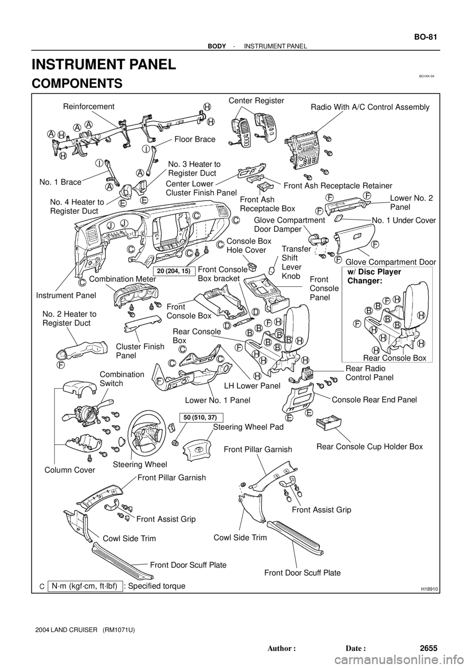
BO1KK-04
H18910
Reinforcement
Floor Brace
No. 1 BraceNo. 3 Heater to
Register Duct
Instrument PanelCenter Register
Radio With A/C Control Assembly
Front Ash Receptacle Retainer Center Lower
Cluster Finish Panel
Front Ash
Receptacle BoxLower No. 2
Panel
Glove Compartment Door
Rear Console Cup Holder Box Front
Console
Panel
Front
Console Box
Rear Console
Box
Rear Radio
Control Panel
Console Rear End Panel Combination Meter
Cluster Finish
Panel
LH Lower Panel
Lower No. 1 Panel No. 2 Heater to
Register Duct
Combination
Switch
Steering WheelSteering Wheel Pad
Front Pillar Garnish
Cowl Side Trim
Front Door Scuff Plate Front Assist Grip No. 4 Heater to
Register Duct
Front Pillar Garnish
Front Assist Grip
Cowl Side Trim
Front Door Scuff Plate
AA
A
A
BBB
C
C
C
C
CC
C
C
C
D
H
A
F
20 (204, 15)
EE
Glove Compartment
Door Damper
50 (510, 37)
BB
Rear Console BoxNo. 1 Under Cover
Console Box
Hole Cover
w/ Disc Player
Changer:
B
Column Cover
Transfer
Shift
Lever
Knob
: Specified torqueN´m (kgf´cm, ft´lbf)
H
H
H
H
I
I
EE
JJ
F
F
F
F
F
H
HH
H
H
BB
BB
HH
H
H
H
H
F
F
F
FF
D Front Console
Box bracket
- BODYINSTRUMENT PANEL
BO-81
2655 Author�: Date�:
2004 LAND CRUISER (RM1071U)
INSTRUMENT PANEL
COMPONENTS
Page 417 of 3115

H20954
H20955
: 2 Clips
H18913
H18912
: 6 Clips BO-92
- BODYINSTRUMENT PANEL
2666 Author�: Date�:
2004 LAND CRUISER (RM1071U)
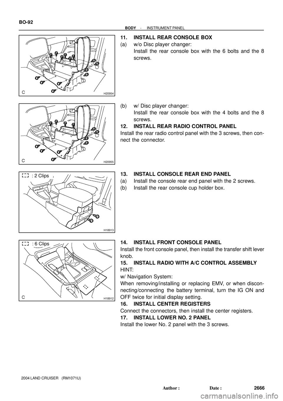
11. INSTALL REAR CONSOLE BOX
(a) w/o Disc player changer:
Install the rear console box with the 6 bolts and the 8
screws.
(b) w/ Disc player changer:
Install the rear console box with the 4 bolts and the 8
screws.
12. INSTALL REAR RADIO CONTROL PANEL
Install the rear radio control panel with the 3 screws, then con-
nect the connector.
13. INSTALL CONSOLE REAR END PANEL
(a) Install the console rear end panel with the 2 screws.
(b) Install the rear console cup holder box.
14. INSTALL FRONT CONSOLE PANEL
Install the front console panel, then install the transfer shift lever
knob.
15. INSTALL RADIO WITH A/C CONTROL ASSEMBLY
HINT:
w/ Navigation System:
When removing/installing or replacing EMV, or when discon-
necting/connecting the battery terminal, turn the IG ON and
OFF twice for initial display setting.
16. INSTALL CENTER REGISTERS
Connect the connectors, then install the center registers.
17. INSTALL LOWER NO. 2 PANEL
Install the lower No. 2 panel with the 3 screws.
Page 422 of 3115

BO4IX-01
H20976
H20977
H20975
: 8 Clips
H20978
BO-84
- BODYINSTRUMENT PANEL
2658 Author�: Date�:
2004 LAND CRUISER (RM1071U)
REMOVAL
1. w/ CD Changer Built In The Audio System:
SHIP MODE SETTING
(a) Take out all of the CDs.
NOTICE:
If they cannot be taken out, do not attempt to take out forci-
bly and send the unit for repair.
(b) Turn the ignition switch to ACC as pressing the ºSEEK
UPº and ºDISCº switches at the same time.
HINT:
When the ship mode has been set, ºSHIPº must be displayed.
(c) Turn the ignition switch to OFF and disconnect the battery
negative cable.
NOTICE:
Connecting the battery negative cable automatically end
the ship mode.
2. REMOVE CENTER REGISTER
(a) Using a moulding remover, remove the center register.
(b) Disconnect the connector.
(c) Use the same manner described above to the other side.
3. REMOVE RADIO WITH A/C CONTROL ASSEMBLY
(a) Remove the 4 bolts.
(b) Disconnect the radio with A/C control assembly cable and
remove the radio with A/C control assembly.
4. w/ CD Changer Built In The Audio System:
SHIP MODE CONFIRMATION
Check that a metal can be seen from holes marked ºSHIPº on
the back of the radio with A/C control assembly.
NOTICE:
If a metal cannot be seen from a hole on the back of the ra-
dio with A/C control assembly, repeat ºSHIP MODEº.
5. REMOVE FRONT DOOR SCUFF PLATES
6. REMOVE COWL SIDE TRIMS
7. REMOVE FRONT DOOR OPENING TRIMS
Page 425 of 3115

H18912
: 6 Clips
H18913
: 2 Clips
H20954
H20955
H21406
: 5 Clips
- BODYINSTRUMENT PANEL
BO-87
2661 Author�: Date�:
2004 LAND CRUISER (RM1071U)
23. REMOVE FRONT CONSOLE PANEL
(a) Remove the transfer shift lever knob.
(b) Using a screwdriver, remove the front console panel.
HINT:
Tape up the screwdriver tip before use.
24. REMOVE CONSOLE REAR END PANEL
(a) Remove the rear console cup holder box.
(b) Remove the 2 screws.
(c) Using a screwdriver, remove the console rear end panel.
HINT:
Tape up the screwdriver tip before use.
25. REMOVE REAR RADIO CONTROL PANEL
Disconnect the connector, then remove the 3 screws and the
rear radio control panel.
26. REMOVE REAR CONSOLE BOX
(a) w/o Disc player changer :
Remove the 6 bolts, the 8 screws and the rear console
box.
(b) w/ Disc player changer :
Remove the 4 bolts, the 8 screws and the rear console
box.
27. REMOVE CENTER LOWER CLUSTER FINISH PANEL
Using a screwdriver, remove the center lower cluster finish pan-
el, then disconnect the connector.
HINT:
Tape up the screwdriver tip before use.
Page 1772 of 3115

DI89V-02
I20790
Key Plate Inserted
ON
OFFWithin. 5secs.
1 Key Plate Not Inserted
23 910Within. 30secs.
Once 9 times DI-938
- DIAGNOSTICSWIRELESS DOOR LOCK CONTROL SYSTEM
1131 Author�: Date�:
PRE-CHECK
1. CHARACTERS OF WIRELESS DOOR LOCK
(a) The operation distance changes according to how cus-
tomers hold the transmitter or where it is used.
(b) Because of using the very weak radio wave, if there is a
strong wave or noise on the frequency being used, the op-
eration distance may become shorter.
2. WIRELESS DOOR LOCK BASIC FUNCTION
(a) Stand on the driver's side. Stay 1 m away from the ve-
hicle.
(b) Turn the transmitter toward the vehicle and press any one
of the transmission switched for 1 sec.
3. INSPECT WIRELESS DOOR LOCK DIAGNOSIS MODE
(a) Start up diagnosis mode.
HINT:
Follow the method below.
(1) Insert the ignition key into the ignition key cylinder.
(2) Remove the ignition key from the ignition key cylin-
der.
(3) Insert the key into the ignition switch.
(4) Turn the ignition switch ON once within 5 sec.
(5) Repeat turning the ignition switch OFF " ON 9
times within 30 sec.
(6) Enter the diagnosis mode, and make sure that the
taillight lights up.
(b) Finishing the Diagnosis Mode.
During the Diagnosis mode, turn the ignition switch OFF
" ON to go back to the normal mode.
At this time make sure that the taillight lights up.
Page 1915 of 3115

2004 LAND CRUISER (EWD548U)
8B HOW TO USE THIS MANUAL
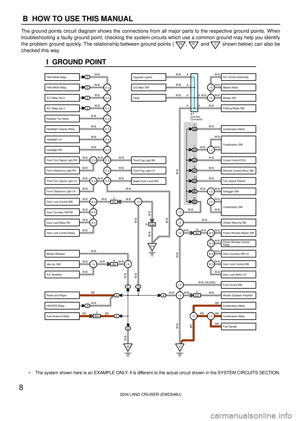
The ground points circuit diagram shows the connections from all major parts to the respective ground points. When
troubleshooting a faulty ground point, checking the system circuits which use a common ground may help you identify
the problem ground quickly. The relationship between ground points (
EA, IB and IC shown below) can also be
checked this way.
5
5
5
5
4
44
4
4 BA15IB18EA2
ID115
IC33 IA12 E 3
W-BW-B W-B W-B W-B
W-B
W-B
W-B
W-B W-B
W-B
W-B W-B
W-B
W-B W-B W-BW-B W-B W-B W-B
W-B
W-B
W-B
W-B W-B W-B
W-B
BR
W-B
BR BRW-BW-B W-B
W-B
W-B
W-B
W-B W-B W-B
W-B
W-B W-B
W-B
W-B
BR W-B
BR BR
BR W-B (4A-GZE)
W-B W-BI 2
I 2
B 5 I 5 I 5 I 5
B 5
B 5
B 5
I 5
I 5
I 3 I 3 E 3
E 3
E 3
E 2
E 4
E 5
E 4
E 5
E 6 E 4 E 4
B 4
EA I 4
B 4
B 4
I 4 I 8
IB IC 443E5
3E6 3G13 3F3 3D1 3B7W-B
W-B
W-B W-B W-B
W-B
W-B
W-B
W-B
W-B
W-B
W-B
W-B
W-B W-BI 6
I 6
I 2 3C7
10A A A A
A
A
Junction
Connector J 1
W-B
W-B
W-B W-B
BR W-B W-B
W-B
W-B W-B
W-B
I GROUND POINT
FAN MAIN Relay
FAN MAIN Relay
A/C Relay No.2
A/C Relay No.3
Radiator Fan Motor
Headlight Cleaner Relay
Headlight LH
Headlight RH
Front Fog Light LH
Brake Fluid Level SW Front Fog Light RH Front Turn Signal Light RH
Front Clearance Light RH
Front Turn Signal Light LH
Front Clearance Light LH
Door Lock Control SW
Door Courtesy SW RH
Door Lock Motor RH
Door Lock Control Relay
Blower Resistor
Idle-Up SW
A/C Amplifier
Radio and Player
HEATER Relay
Auto Antenna MotorA/C Control Assembly
Blower Motor
Blower SW
Parking Brake SW
Combination Meter
Combination SW
Cruise Control ECU
Remote Control Mirror SW
Turn Signal Flasher
Defogger SW
Unlock Warning SW
Power Window Master SW
Power Window Control
Relay
Door Courtesy SW LH
Door Lock Control SW
Door Lock Motor LH
Fuel Control SW
Woofer Speaker Amplifier
Combination Meter
Combination Meter
Fuel Sender Cigarette Lighter
O/D Main SW
Clock
Combination SW
*The system shown here is an EXAMPLE ONLY. It is different to the actual circuit shown in the SYSTEM CIRCUITS SECTION.