1986 CHEVROLET CORVAIR steering wheel
[x] Cancel search: steering wheelPage 5 of 56
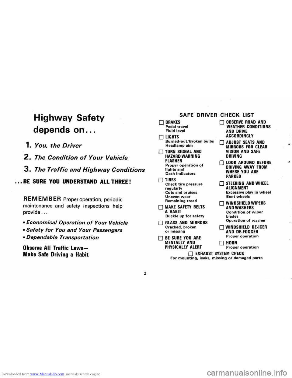
Downloaded from www.Manualslib.com manuals search engine Highway Safety
depends on ...
1. You, the Driver
2. The Condition of Your Vehicle
3. The Traffic and Highway Conditions
••• BE SURE YOU UNDERSTAND ALL THREE!
REMEMBER Proper operation, periodic
maintenance and safety inspections help
provide
...
• Economical Operation of Your Vehicle
• Safety for You and Your Passengers
• Dependable Transportation
Observe All Traffic Laws
Make Safe Driving a Habit
2
SAFE DRIVER CHECK LIST
o BRAKES Pedal travel Fluid level
o LIGHTS Burned-out/Broken bulbs Headlamp aim
o TURN SIGNAL AND HAZARD WARNING FLASHER Proper operation of lights and Dash indicators
o TIRES Check tire pressure regularly Cuts and bruises Uneven wear Remaining tread
o MAKE SAFETY BELTS A HABIT Buckle up for safety
o GLASS AND MIRRORS Cracked, broken or missing
o BE SURE YOU ARE
o OBSERVE ROAD AND WEATHER CONDITIONS AND DRIVE ACCORDINGLY
o ADJUST SEATS AND MIRRORS FOR CLEAR VISION AND SAFE DRIVING
o LOOK AROUND BEFORE DRIVING AWAY FROM WHERE YOU ARE PARKED
o STEERING AND WHEEL ALIGNMENT Excessive play in wheel Bent wheels
o WINDSHIELD WIPERS AND WASHERS Condition of wiper blades Operation of washer
o WINDSHIELD DE-ICER AND DE-FOGGER Proper operation
MENTALLY AND 0 HORN PHYSICALLY ALERT Proper operation
o EXHAUST SYSTEM CHECK For mounting, leaks, missing or damaged parts
Page 8 of 56
Downloaded from www.Manualslib.com manuals search engine STANDARD NO. III Rearview Mirrors
Purpose and Scope. This standard specifies requirements for
rearview mirrors to provide the driver with a clear and rea
sonably unobstmcted view to the rear.
STANDARD NO. 203 Impact Protection for the Driver From the Steering Control System Purpose and Scope. This standard specifies requirements for
steering control systems that will minimize chest, neck, and facial injuries to the driver as a result of impact.
STANDARD NO. 204
Steering Control Rearward Displacement
Purpose and Scope. This standard specifies requirements
limiting the rearward displacement of the steering control
into the passenger compartment to reduce the likelihood of chest, neck, or head injury.
STANDARD NO. 205 Glazing Materials
Purpose and Scope. This standard specifies requirements
for glazing materials to reduce lacerations to the face, scalp, and neck, and to minimize the possibility of occupants being
thrown through the vehicle windows in collisions.
STANDARD NO. 206 Door Latches and Door Hinge Systems Purpose and Scope. This standard specifies load require
m ents for door latches and door hinge systems to minimize
the probability of occupants being thrown from the vehicle
in a collision.
STANDARD NO. 207 Anchorage of Seats Purpose and Scope. This standard establishes requirements
for seats, their attachment assemblies, and their installation
to minimize the possibility of failure by forces acting on the seat as a result of vehicle impact.
5
STANDARD NO. 208
Seat Belt Installations
Purpose and Scope. This standard establishes requirements
for seat belt installations.
STANDARD NO. 2090
Seat Belt Assemblies
Purpose and Scope. This standard specifies requirements
for seat belt assemblies.
STANDARD NO. 210
S ea t Belt Assembly Anchorages
Purpose and Scope. This standard specifies the requirements
for seat belt assembly anchorages to ensure proper location
for effective occupant restraint and reduce the likelihood
of failure in collisions.
STANDARD NO. 211
Wheel Nuts, Wheel Discs, and Hub Caps
Purpose and Scope. This standard precludes the use of wheel nuts, wheel discs, and hub caps that constitute a hazard to
pedestrians and cyclists .
STANDARD NO. 301 Fuel Tanks, Fuel Tank Filler Pipes, and Fuel Tank Con-
nections
Purpose
and Scope. This standard specifies requirements
for the integrity and security of fuel tanks, fuel tank filler
pipes, and fuel tank connections to minimize fire hazard as
a result of collision.
PUBLIC LAW 87·637 (1962) * An Act to provide that hydraulic brake fluid sold or shipped in commerce for use in motor vehicles shall meet cer
tain specifications prescribed by the Secretary of Commerce. The requirements of this law were issued as standards when the National Traffic and Motor Vehicle Safety Act of 1966
was enacted.
"The Sea t (Lap) Belt and Brak e fluid standards are applicable
to all 1968 models of affected vehicles.
Page 15 of 56
Downloaded from www.Manualslib.com manuals search engine TRANSMISSION OPERATING TIPS
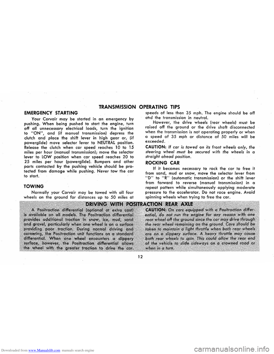
EMERGENCY STARTING
Your Corvair may be started in an emergency by
pushing. When being pushed to start the engine, turn
off all unnecessary electrical loads, turn the ignition to "ON", and (if manual transmission) depress the
clutch and place the shift lever in high gear or, (if
powerglide) move selector lever to NEUTRAL position.
Release the clutch when car speed reaches 10 to 15 miles per hour (manual transmission); move the selector
lever to LOW position when car speed reaches 20 to
25 miles per hour (powerglidel. Bumpers and other
parts contacted by the pushing vehicle should be pro
tected from damage while pushing. Never tow the car
to start.
TOWING
Normally your Corvair may be towed with all four
wheels on the ground for distances up to 50 miles at
12
speeds of less than 35 mph. The engine should be off
ahd the transmission in neutral.
However, the drive wheels (rear wheels) must be
raised off the ground or the drive shaft disconnected
when the transmission
is not operating properly or when
a speed
of 35 mph or distance of 50 miles will be exceeded.
CAUTION: If car is towed on its front wheels only, the
steering wheel must
be secured with the wheels in a
straight ahead position .
ROCKING CAR
If it becomes necessary to rock the car to free it
from sand, mud or snow, move the selector lever from "D" to "R" (automatic transmission) or the shift lever
from forward to reverse (manual transmission) in a
repeat pattern while simultaneously applying moderate
pressure to the accelerator. Do not race engine. Avoid
spinning wheels when trying to free the car.
Page 19 of 56
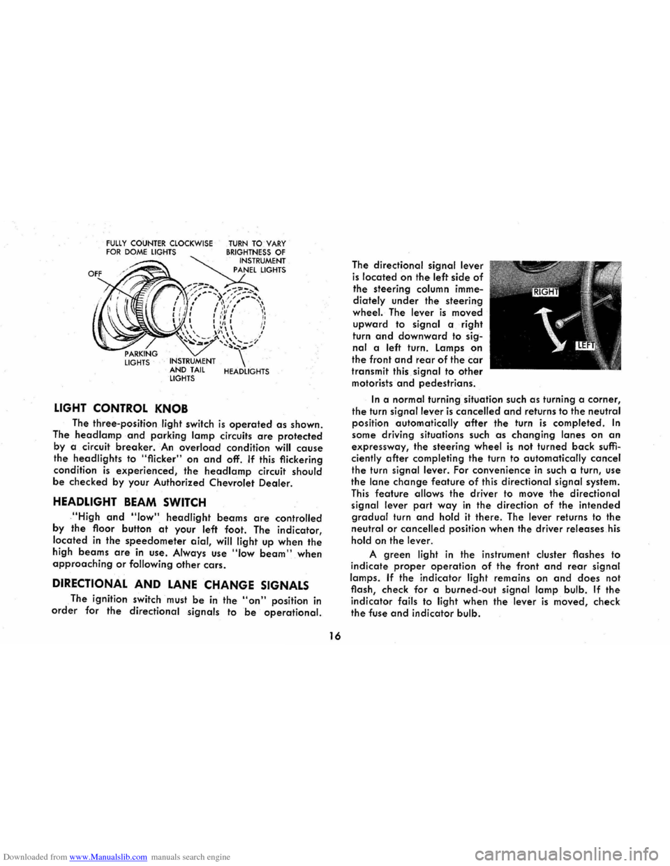
Downloaded from www.Manualslib.com manuals search engine FULLY COUNTER CLOCKWISE FOR DOME LIGHTS
LIGHTS INSTRUMENT
AND TAIL
LIGHTS
LIGHT CONTROL KNOB
TURN TO VARY BRIGHTNESS OF INSTRUMENT
PANEL LIGHTS
HEADLIGHTS
The three-position light switch is operated as shown.
The
head lamp and parking lamp circuits are protected
by a circuit breaker. An overload condition will cause
the headlights to "flicker" on and off. If this flickering
condition
is experienced, the headlamp circuit should
be checked by your Authorized Chevrolet Dealer.
HEADLIGHT BEAM SWITCH
,"High and "low" headlight beams are controlled
by
the floor button at your left foot. The indicator,
located
in the speedometer aial, will light up when the
high beams are in use . Always use "Iow beam" when approaching or following other cars.
DIRECTIONAL AND LANE CHANGE SIGNALS
The ignition switch must be in the "on" position in
order for the directional signals to be operational.
16
The directional signal lever
is located on the left side of
the steering column imme
diately
under the steering
wheel. The lever is moved
upward to signal a right
turn
and downward to sig
nal a left turn. Lamps on
the front and rear of the car
transmit this signal to other
motorists and pedestrians.
In a normal turning situation such as turning a corner,
the turn signal lever is cancelled and returns to the neutral
position automatically
after the turn is completed. In
some driving situations such as changing lanes on an
expressway, the steering wheel is not turned back suffi
ciently after completing the turn to automatically cancel
the turn signal lever. For convenience in such a turn, use
the lane change feature of this directional signal system.
This feature allows the driver to move the directional
signal lever
part way in the direction of the intended
gradual turn and hold it there. The lever returns to the
neutral or cancelled position when the driver releases his
hold on the lever.
A green light in the instrument cluster flashes to
indicate
proper operation of the front and rear signal
lamps.
If the indicator light remains on and does not
flash, check for a burned-out
signal lamp bulb. If the
indicator fails to light when the lever is moved, check
the fuse and indicator bulb.
Page 20 of 56
Downloaded from www.Manualslib.com manuals search engine If the system is not functioning properly, a legal hand
signal should be given, since failure to indicate a turn
is considered a moving traffic violation in many states.
Always signal for a turn
at a reasonable distance before actu 'ally making it.
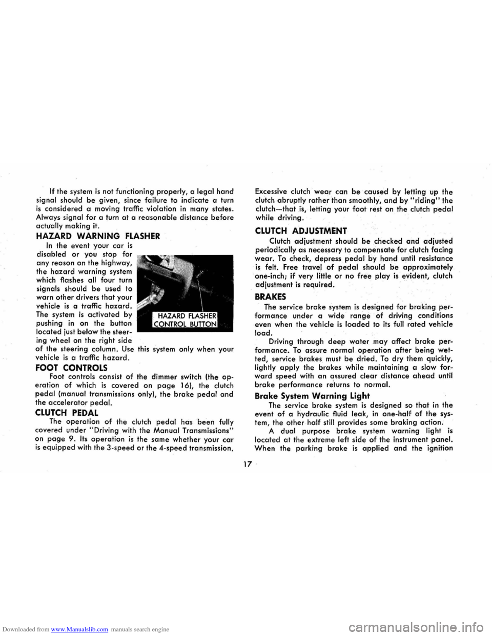
HAZARD WARNING FLASHER
In the event your car is
disabled or you stop for
any reason on the highway,
the
hazard warning system
which flashes all four turn
signals should
be used to
warn
other drivers that your
vehicle
is a traffic hazard.
The system is activated by
pushing
in on the button
located just
below the steer
ing wheel on the right side
of the steering column. Use this system only when your
vehicle
is a traffic hazard.
FOOT CONTROLS Foot controls consist of the dimmer switch (the op
eration of which is covered on page 16), the clutch
pedal (manual transmissions only), the brake pedal and
the accelerator pedal.
CLUTCH PEDAL The operation of the clutch pedal has been fully
covered under
"Driving with the Manual Transmissions"
on
page 9. Its operation is the same whether your car
is equipped with the 3-speed or the 4-speed transmission. Excessive
clutch
wear can be caused by letting up the
clutch abruptly
rather than smoothly, and by "riding" the
clutch-that is, letting your foot rest on the clutch pedal
while driving .
CLUTCH ADJUSTMENT
Clutch adjustment should be checked and adjusted
periodically as necessary to compensate for clutch facing
wear. To check, depress pedal.by hand until resistance
is felt. Free travel of pedal should be approximately
one-inch;
if very little or no free play is evident, clutch
adjustment
is required.
BRAKES
The service brake system is designed for braking per
formance under a wide range of driving conditions
even when the vehicle
is loaded to its full rated vehicle
load. Driving through deep water may affect brake per
formance. To assure normal operation after being wet
ted, service brakes must be dried. To dry them quickly,
lightly
apply the brakes while maintaining a slow for"
ward speed with an assured clear distance ahead until
brake performance re'turns to normal.
Brake System Warning Light
The service brake system is designed so that in the
event of a hydraulic fluid leak,
in one-half of the sys
tem, the other half still provides some braking action.
A dual purpose brake system warning light is
located at the extreme left side of the instrument panel.
When the parking brake is applied and the ignition
17 .
Page 21 of 56
Downloaded from www.Manualslib.com manuals search engine switch is turned to the "ON" position, the warning light
glows red to indicate to the operator that the parking
brake has not been fully released. This also indicates
that the brake warning light is operational. If the light does not come on, have your Corvair Dealer correct
the trouble as soon as possible. The other function of
this light is to indicate a malfunction in the regular braking system. In the event of broken brake lines,
major brake fluid loss, air in the brake lines or a pres
sure deviation between the front · and the rear wheel
brake lines, the light will come on and stay on while
braking .
In this event, the vehicle should not be driven
until
the cause has been determined and, if necessary,
corrected.
Automatic Brake Adjusters
All Corvair models are equipped with self-adjusting
brakes which eliminates periodic brake adjustments. The
self-adjusting mechanism
is actuated, as needed, when
ever the car is moved in reverse and the brakes applied.
It is possible, however, for excessive brake pedal travel
to
develop if the required reverse movement with a
brake application does not take place during a pro
longed
period of stop and go forward driving. Should
this occur,
the car should be driven backward and for
ward with the brakes applied at the end of each direc
tional movement, until the brake pedal travel is back to
normal. If this procedure fails to restore normal pedal
travel, or if any abnormally rapid increase in pedal
travel is experienced, immediate inspection should be
made by your Authorized Chevrolet Dealer. Care should
18
be exercised to assure that full brake pedal travel can
not be obstructed by improper floor mats or other inter
fering material under the pedal.
PARKING BRAKE
The parking brake operates by cables on the rear
wheel brakes independent of the regular foot brake hydraulic system. The brake system warning light will
be "ON" whenever the parking brake is not fully re
leased and the ignition switch is "ON". Never drive the car with the parking brake engaged. .
Pull the parking brake lever as far as possible to
engage the brake. The lever will remain in the applied
position until released. To release, pull the handle to
ward the steering wheel, depress the "trigger" and
allow the handle to return to the released position. CAUTION: When leaving the car unattended, always
fully apply the parking brake.
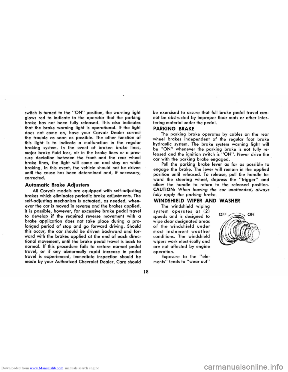
WINDSHIELD WIPER AND WASHER
The windshield wiping
system operates at (2)
speeds and is designed to
wipe clear
designated areas
of the windshield under
most inclement weather
conditions. The windshield
wipers work
electrically and
are not affected by engine
operation.
Exposure to the "ele
ments" tends to "wear out"
OFF~ON
Page 25 of 56
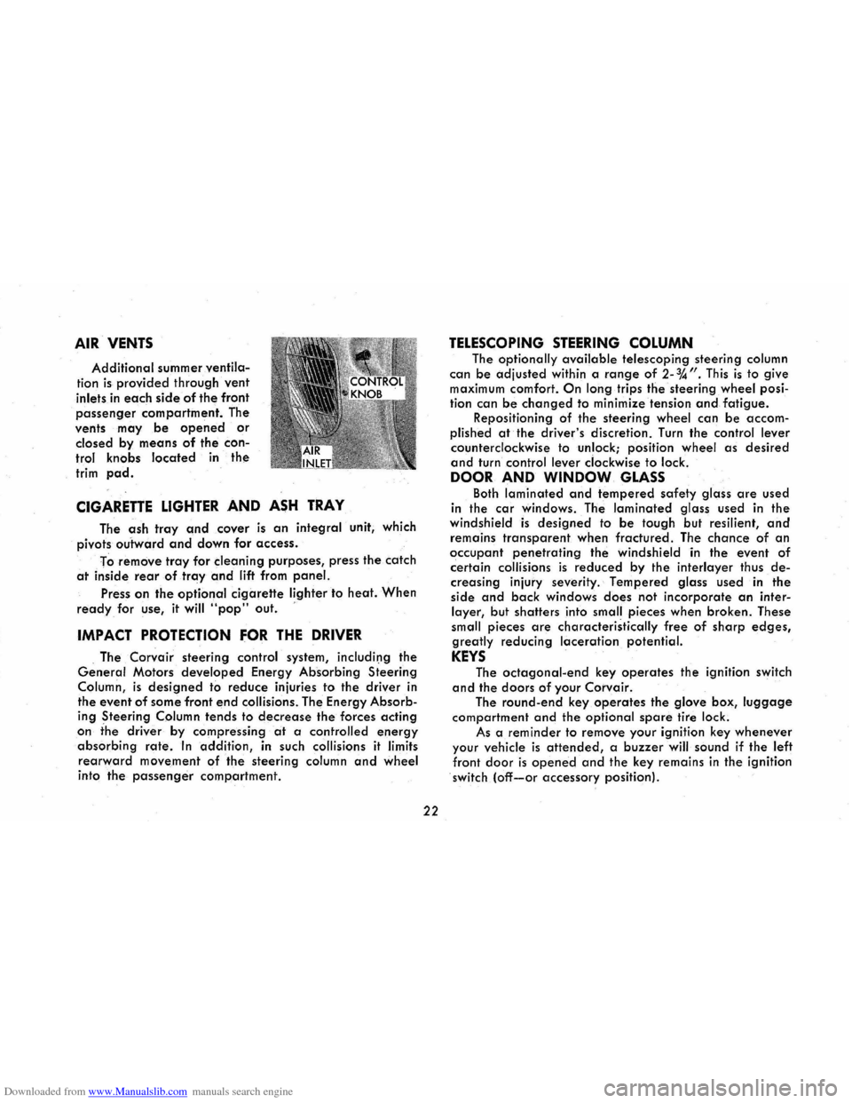
Downloaded from www.Manualslib.com manuals search engine AIR VENTS
Additional summer ventila
tion is provided through vent
inlets in each side of the front
passenger compartment. The
vents
may be opened or
closed by means of the con
trol knobs located in the
trim pad.
CIGARETTE LIGHTER AND ASH TRAY
The ash tray and cover is an integral unit, which
pivots
outward and down for access.
To
remove tray for cleaning purposes, press the catch
at inside rear of tray and lift from panel.
Press on the optional cigarette lighter to heat. When
ready for use, it will "pop" out. '
IMPACT PROTECTION FOR THE DRIVER
. The Corvair steering control system, includil)g the
General Motors developed Energy Absorbing Steering
Column,
is designed to reduce injuries to the driver in
the event
of some front end collisions. The Energy Absorb
ing Steering Column tends to decrease the forces acting
on the driver by compressing at a controlled energy
absorbing rate. In addition, in such collisions it limits
rearward movement of the steering column and wheel
into the passenger compartment.
22
TELESCOPING STEERING COLUMN
The optionally available telescoping steering column
can be adjusted
within a range of 2-%". This is to give maximum comfort. On long trips the steering wheel posi
tion can
be changed to minimize tension and fatigue. Repositioning of the steering wheel can be accom
plished
at the driver's discretion. Turn the control lever
counterclockwise to unlock; position wheel as desired
and turn control lever clockwise to lock.
DOOR AND WINDOW GLASS
Both laminated and tempered safety glass are used
in the
car windows. The laminated glass used in the windshield is designed to be tough but resilient, and
remains transparent when fractured. The chance of an
occupant penetrating the windshield in the event of
certain collisions is reduced by the interlayer thus de
creasing injury severity. Tempered glass used in the
side
and back windows does not incorporate an inter
layer, but shatters into small pieces when broken. These
small pieces
are characteristically free of sharp edges,
greatly reducing laceration potential.
KEYS
The octagonal-end key operates the ignition switch
and the doors of your Corvair.
The round-end key operates the glove box, luggage
compartment and the optional spare tire lock.
As a
reminder to remove your ignition key whenever
your vehicle is attended, a buzzer will sound if the left
front door is opened and the key remains in the ignition
switch (off-or accessory position).
Page 30 of 56
Downloaded from www.Manualslib.com manuals search engine deflect or collapse under certain impacts. The soft vinyl
cover over the mirror support base further protects the occupants.
CAUTION: It is important that the driver check the
mirrors
for proper positioning, and that he make frequent
use of the mirrors to be constantly aware of the rearward
aspect
of his total driving situation.
The windshield wiper arms and blades, inside wind
shield moldings,
horn and steering wheel ornamentation,
inside rearview mirror frame and mounting bracket
incorporate low-gloss finishes. This reduces annoying
glare in the driver's forward field of view and provides
a
safer, more comfortable driving environment.
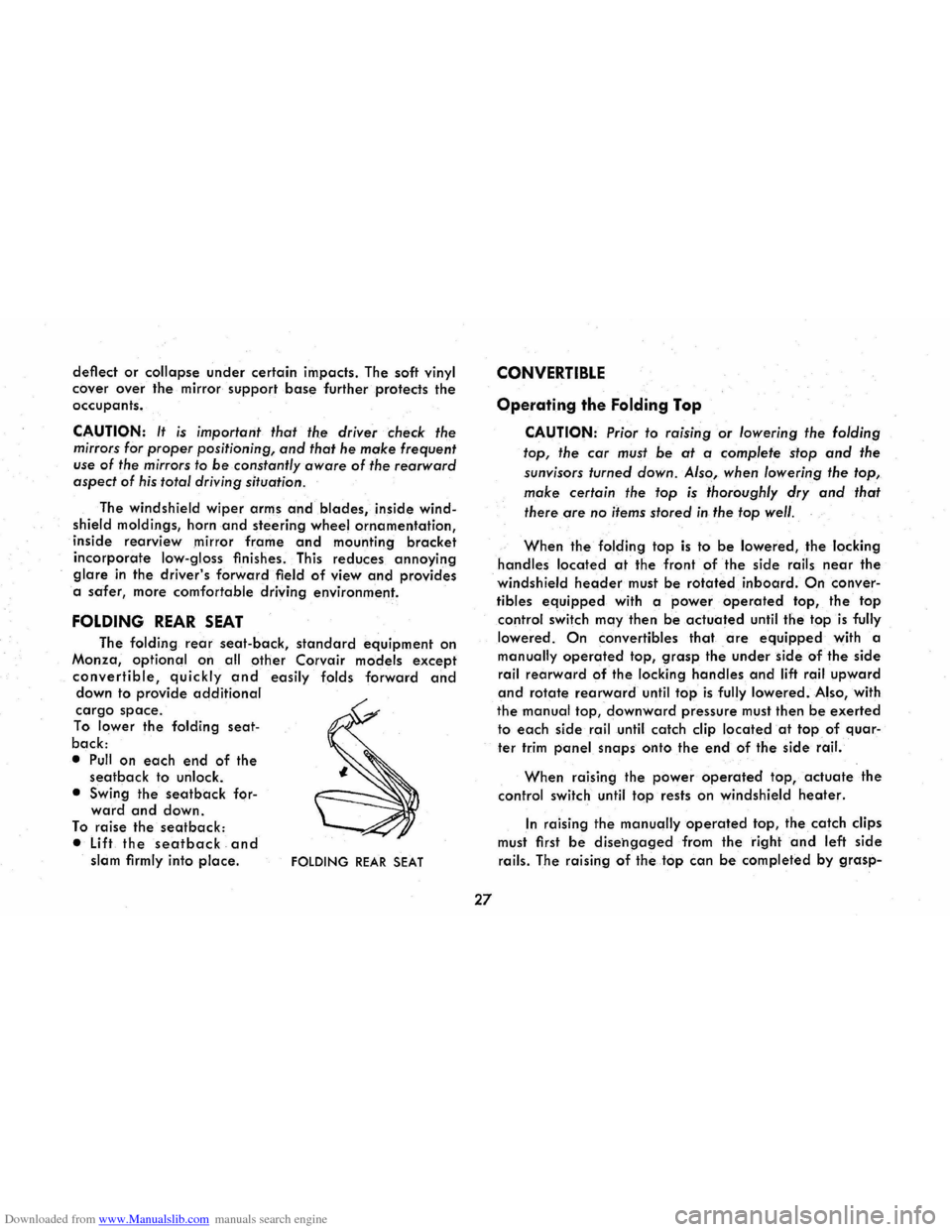
FOLDING REAR SEAT
The folding rear seat-back, standard equipment on
Monza,
optional on all other Corvair models except
convertible, quickly and easily folds forward and down to provide additional
cargo space.
To lower the folding seat
back:
• Pull on each end of the seatback to unlock.
• Swing
the seatback forward and down.
To raise the seatback:
• Lift the seat back and slam firmly into place. FOLDING REAR SEAT
27
CONVERTIBLE
Operating the Folding Top
CAUTION: Prior to raising or lowering the folding
top, the
car must be at a complete stop and the
sunvisors turned down. Also, when lowering the top,
make certain the top is thoroughly dry and that
there are
no items stored in the top well.
When the folding top is to be lowered, the locking
handles located at the front of the side rails near the
windshield header must be rotated inboard. On conver
tibles
equipped with a power operated top, the top
control switch may then be actuated until the top is fully
lowered.
On convertibles that are equipped with a
manually operated top, grasp the under side of the side
rail rearward of the locking handles and lift rail upward
and rotate rearward until top is fully lowered. Also, with
the manual top, downward pressure must then be exerted
to each side rail until catch clip located at top of quar
ter trim panel snaps onto the e.nd of the side rail.
When raising the power operated top, actuate the
control switch until top rests on windshield heater.
In raising the manually operated top, the catch clips
must first
be disehgaged from the right and left side
rails. The raising of the top can be completed by grasp-