1986 CHEVROLET CORVAIR heater
[x] Cancel search: heaterPage 17 of 56
Downloaded from www.Manualslib.com manuals search engine operating, except the GEN-FAN indicator rna)' flicker
when
engine is idling.
CAUTION: If either of these indicators light
while .
car is being. -driYen, immediately follow the
procedure outlined .vnder "EMERGENCY OPER
ATING INSTRUCTIONS," so car may be driyen
to the nearest service facility.
BRAKE SYSTEM WARNING LIGHT
This dual purpose indicator light operates as
follows:
With parking brake applied the red light will light
when
the ignition switch is turned on.
As a dual service brake system warning, the red
light will come on when the brake pedal is depressed
if low pressure has developed in either the front or
rear brake system. Have your authorized Chevrolet
dealer locate and correct the trouble immediately.
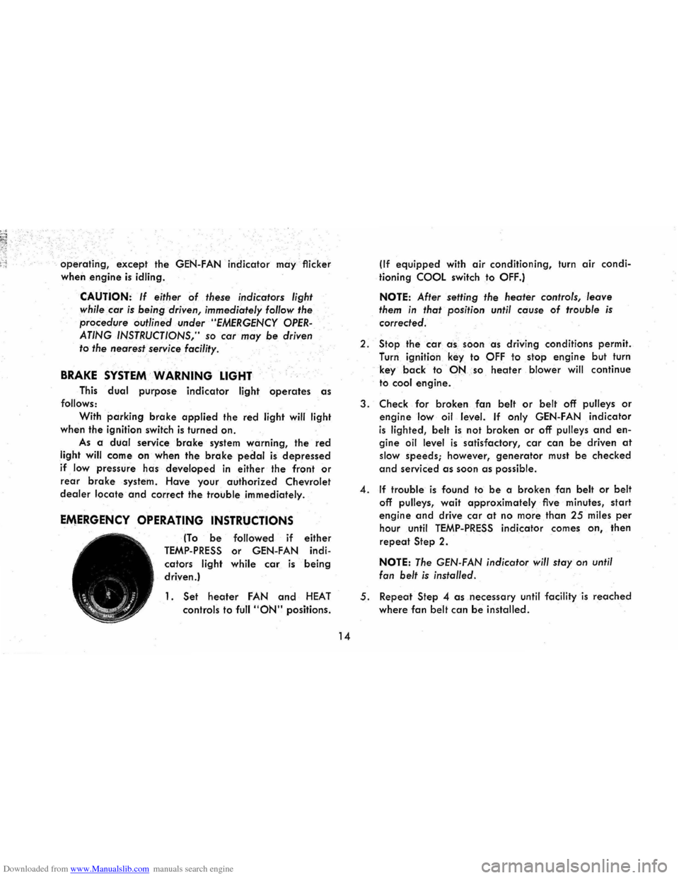
EMERGENCY OPERATING INSTRUCTIONS
(To be followed if either
TEMP-PRESS or GEN-FAN indi
cators
light while car is being
driven.)
1. Set heoter FAN and HEAT
controls to full "ON" positions.
14
(If equipped with air conditioning, turn air condi
tioning
COOL switch to OFF.)
NOTE: After setting the heater controls, leave
them in that position until cause of trouble is
corrected.
2.
Stop the car a -s , soon as driving conditions permit.
furn ignition
key to OFF to stop engine but turn
key
back to·-PNso heoter blower will continue
to
cool engine.
3. Check for broken fan belt or belt off pulleys or
engine low oil level. If only GEN-FAN indicator
is lighted, belt is not broken or off pulleys and en
gine oil level is satisfactory, car can be driven at
slow speeds; however, generator must be checked
and serviced as soon as possible.
4. If trouble is found to be a broken fan belt or belt
off pulleys, wait approximately five minutes, start
engine and drive car at no more than 25 miles per
hour until TEMP-PRESS indicator comes on, then
repeat Step 2.
NOTE: The GEN-FAN indicator will stay on until
fan
belt is installed.
5. Repeat Step 4 as necessary until facility is reached
where fan belt can be installed.
Page 22 of 56
Downloaded from www.Manualslib.com manuals search engine the rubber in the wiper blades. Check the blades periodi
cally and replace them whenever they show signs of
streaky or otherwise poor wiping action.
Pressing
once on the windshield wiper and washer
knob will cause the washer to squirt a measured amount
of water or other cleaning agent onto the glass and will
at the same time turn on the wiper. The wiper must
then
be manually turned off, when the washing process
is completed.
Water or cleaning agent needed for operation of
the windshield washers is carried in a plastic water jar
attached to the dash panel withiri the luggage compart
ment. Keep the
washer jar Ailed to a level 2 inches below
the top of
the jar.
CAUTION: Be sure to have the fluid level in the washer
reservoir
checked regularly, with special attention to
keeping the reservoir fil/ed during periods of heavy use.
GM Washer Solvent should be used as directed to pre
vent freezing
damage and for better cleaning of the
windshield under
aI/ conditions. Do not use radiator anti
freeze as this will cause paint damage.
In the winter, fill the washer jar only % full to allow
for expansion if the solution freezes. In freezing weather,
pre-warm the windshield using the heater defrosters before using the washers.
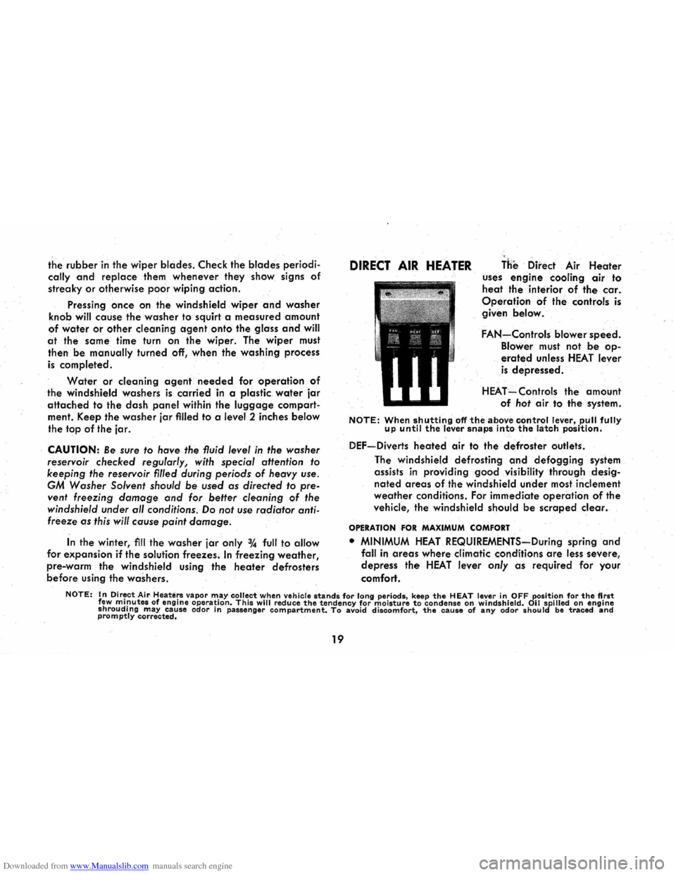
DIRECT AIR HEATER THe Direct Air Heater uses engine cooling air to
heat the interior of the car.
Operation of the controls is
given below.
FAN-Controls blower speed.
Blower must not be op
erated unless HEAT lever
is depressed.
HEAT=Controls the amount
of hot air to the system.
NOTE: When shutting off the above control lever, pull fully up until the lever snaps into the latch position.
DEF-Diverts heated air to the defroster outlets.
The windshield defrosting
and defogging system
assists
in providing good visibility through desig
nated areas of the windshield under most inclement
weather conditions. For immediate operation of the
vehicle, the windshield should
be scraped clear.
OPERATION FOR MAXIMUM COMFORT
• MINIMUM HEAT REQUIREMENTS-During spring and
fall in areas where climatic conditions are less severe,
depress the HEAT lever only as required for your
comfort.
NOTE: In Dir~ct Air Heauirs vapor m.ay collectwhen vehicle stands for long periods, keep the HEAT lever in OFF position for the first few ml!lutes of engine operatIon. This will reduce the tendency for moisture to condense on windshield. 011 spilled on engine shroudIng may cause odor in passenger compartment. To avoid discomfort, the cause of any odor should be traced and promptly corrected.
19
Page 23 of 56
Downloaded from www.Manualslib.com manuals search engine • MAXIMUM HEAT REQUIREMENTS-Depress HEAT lever
to extreme down position.
If heat becomes exces
sive, pull up HEAT knob to desired position.
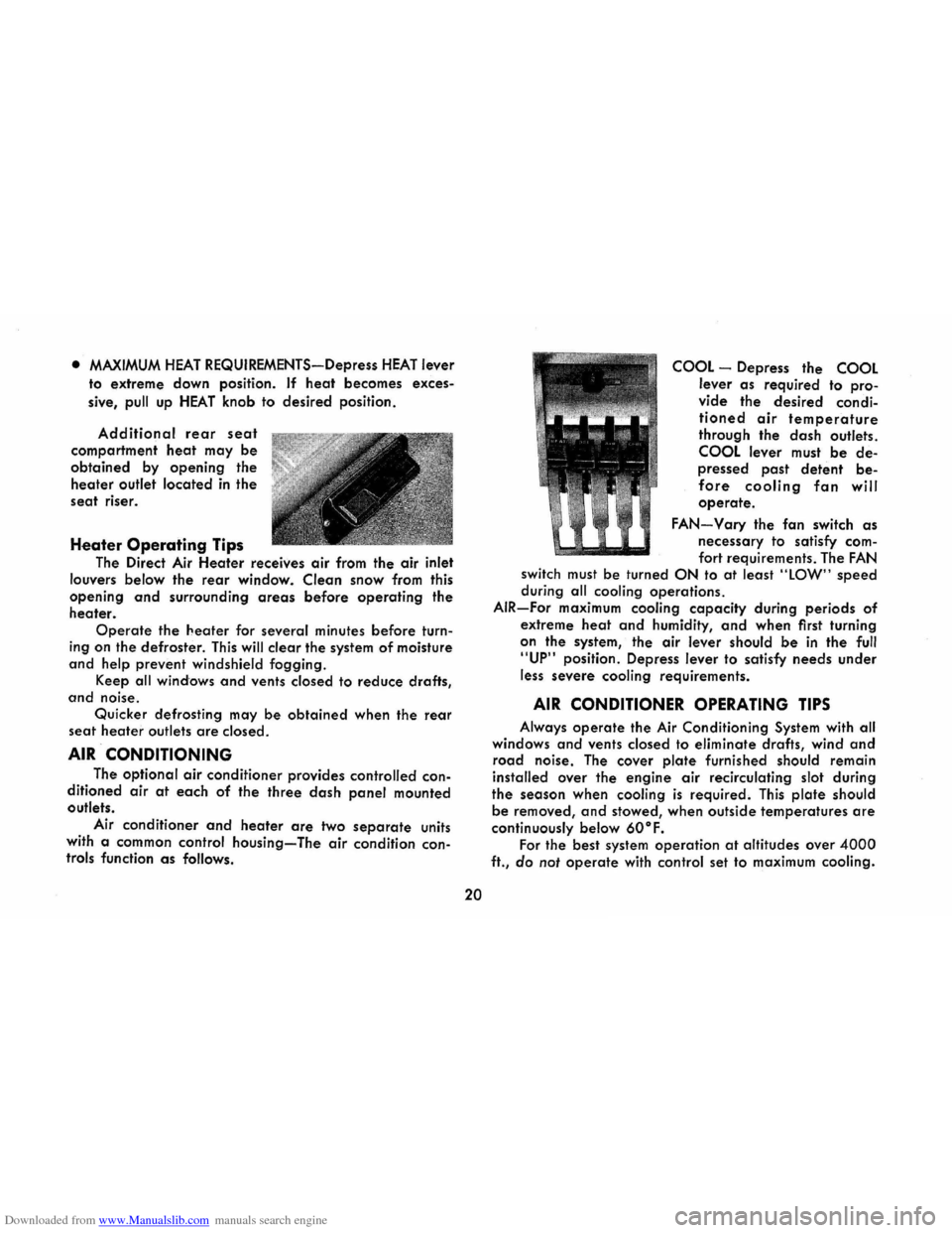
Additional rear seat
compartment heat may be
obtained by opening the
heater outlet located in the
seat riser.
Heater Operating Tips
The Direct Air Heater receives air from the air inlet
louvers below the
rear window. Clean snow from this
opening
and surrounding areas before operating the
heater.
Operate the heater for several minutes before turn
ing on the defroster. This will clear the system of moisture
and help prevent windshield fogging.
Keep
all windows and vents closed to reduce drafts,
and noise.
Quicker defrosting may
be obtained when the rear
seat heater outlets are closed.
AIR CONDITIONING
The optional air conditioner provides controlled con
ditioned air at each of the three dash panel mounted
outlets.
Air conditioner
and heater are two separate units
with a common control
housing-The air condition controls function as follows.
20
COOL -Depress the COOL
lever as required to pro
vide the desired condi
tioned air temperature
through the dash outlets.
COOL lever must be de
pressed past detent be
fore cooling fan will
operate.
FAN-Vary the fan switch as
necessary to satisfy com
fort requirements. The FAN
switch must be turned ON to at least "lOW" speed
during all cooling operations.
AIR-For maximum cooling capacity during periods of
extreme heat and humidity, and when first turning
on the system, the air lever should
be in the full
"UP" position. Depress lever to satisfy needs under
less
severe cooling requirements.
AIR CONDITIONER OPERATING TIPS
Always operate the Air Conditioning System with all
windows
and vents closed to eliminate drafts, wind and
road noise. The cover plate furnished should remain
installed over the engine air recirculating slot during
the season when cooling
is required. This plate should
be removed, and stowed, when outside temperatures are
continuously below 60°F.
For the best system operation at altitudes over 4000
ft., do not operate with control set to maximum cooling.
Page 30 of 56
Downloaded from www.Manualslib.com manuals search engine deflect or collapse under certain impacts. The soft vinyl
cover over the mirror support base further protects the occupants.
CAUTION: It is important that the driver check the
mirrors
for proper positioning, and that he make frequent
use of the mirrors to be constantly aware of the rearward
aspect
of his total driving situation.
The windshield wiper arms and blades, inside wind
shield moldings,
horn and steering wheel ornamentation,
inside rearview mirror frame and mounting bracket
incorporate low-gloss finishes. This reduces annoying
glare in the driver's forward field of view and provides
a
safer, more comfortable driving environment.
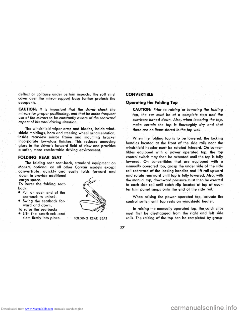
FOLDING REAR SEAT
The folding rear seat-back, standard equipment on
Monza,
optional on all other Corvair models except
convertible, quickly and easily folds forward and down to provide additional
cargo space.
To lower the folding seat
back:
• Pull on each end of the seatback to unlock.
• Swing
the seatback forward and down.
To raise the seatback:
• Lift the seat back and slam firmly into place. FOLDING REAR SEAT
27
CONVERTIBLE
Operating the Folding Top
CAUTION: Prior to raising or lowering the folding
top, the
car must be at a complete stop and the
sunvisors turned down. Also, when lowering the top,
make certain the top is thoroughly dry and that
there are
no items stored in the top well.
When the folding top is to be lowered, the locking
handles located at the front of the side rails near the
windshield header must be rotated inboard. On conver
tibles
equipped with a power operated top, the top
control switch may then be actuated until the top is fully
lowered.
On convertibles that are equipped with a
manually operated top, grasp the under side of the side
rail rearward of the locking handles and lift rail upward
and rotate rearward until top is fully lowered. Also, with
the manual top, downward pressure must then be exerted
to each side rail until catch clip located at top of quar
ter trim panel snaps onto the e.nd of the side rail.
When raising the power operated top, actuate the
control switch until top rests on windshield heater.
In raising the manually operated top, the catch clips
must first
be disehgaged from the right and left side
rails. The raising of the top can be completed by grasp-
Page 37 of 56
Downloaded from www.Manualslib.com manuals search engine level, remove the oil gauge rod (dip stick), wipe it
clean and reinsert it firmly for an accurate reading.
The oil level should be maintained in the safety margin,
neither going above the FULL line nor below the ADD
mark. Reseat the gauge firmly after taking the reading.
DO NOT OVERFilL.
COOLING SYSTEM CARE
The engine fan belt should be checked for tightness
at regular intervals. When a new belt is needed use only
the approved premium belt available from your Chev
rolet dealer. If any other belt is installed, replace with
recommended belt when possible.
Watch the TEMP-PRESS and GEN-FAN indicators on the
instrument
panel for signs of overheating.
Air inlet louvers, located in the panel below the rear
window, supply air for engine combustion and cooling
and for the Direct Air Heater. Make sure the louvers are
never sealed or blocked.
TIRES
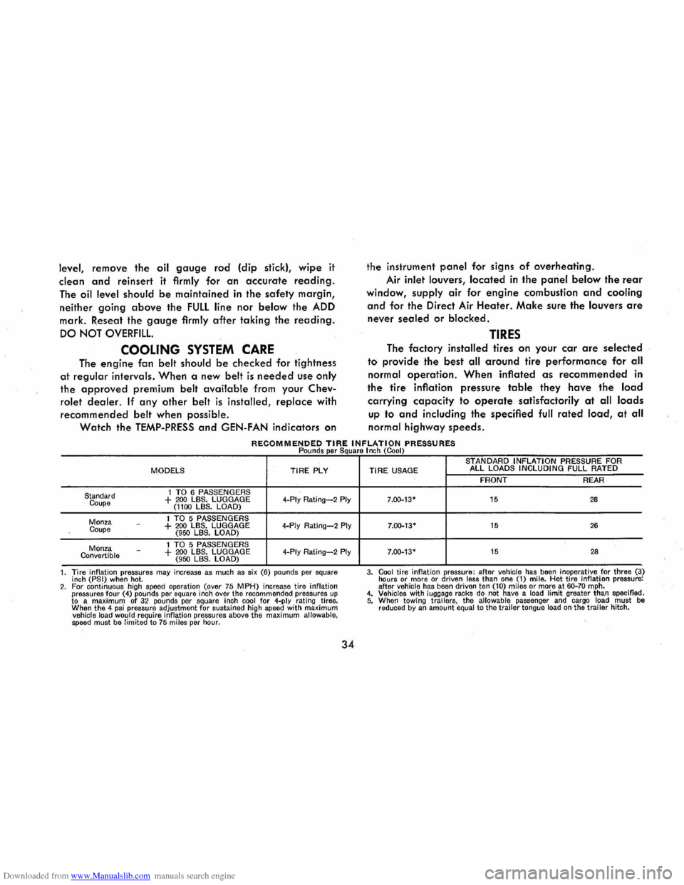
The factory installed tires on your car are selected
to provide the best all around tire performance for all
normal operation. When inflated as recommended in
the
tire inflation pressure table they have the load
carrying capacity to operate satisfactorily at all loads
up to and including the specified full rated load, at all
normal highway speeds.
RECOMMENDED TIRE INFLATION PRESSURES Pounds per Square I nch (Cool)
MODELS TIRE PLY
1 TO 6 PASSENGERS Standard
Coupe + 200 LBS. LUGGAGE 4-Ply Rating-2 Ply (1100 LBS. LOAD)
1 TO 5 PASSENGERS Monza
Coupe -+ 200 LBS. LUGGAGE 4-Ply Rating-2 Ply (950 LBS. LOAD)
1 TO 5 PASSENGERS Monza Convertible -+ 200 LBS. LUGGAGE 4-Ply Rating-2 Ply (950 LBS. LOAD)
1. Tire inflation pressures
may increase as much as six (6) pounds per square
inch (PSI) when hot. 2. For continuous high speed operation (over 75 MPH) increase tire inflation pressures four (4) pounds per square inch over the recommended pressures up to a maximum of 32 pounds per square inch cool for 4-ply rating tires.
When the 4 psi pressure adjustment for sustained high speed with maximum vehicle load would require inflation pressures above the maximum allowable, speed must be limited to 75 miles per hour.
34
STANDARD INFLATION PRESSURE FOR TIRE USAGE ALL LOADS INCLUDING FULL RATED
FRONT REAR
7.00-13-15 28
7.00-13· 15 26
7.00-13· 15 28
3. Cool tire inflation pressure: after vehicle has been inoperative for three (3)
hours or more or driven less than one (1) mile. Hot tire inflation pressure:
after vehicle has been driven ten (10) miles or more at 60-70 mph. 4. Vehicles with luggage racks do not have a load limit greater than specified. 5. When towi ng trai lers, the allowable passenger and cargo load must be reduced by an amount equal to the trailer tongue load on the trailer hitch.
Page 48 of 56
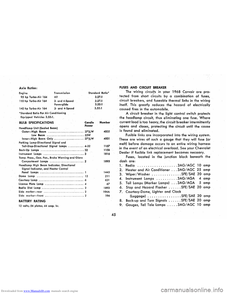
Downloaded from www.Manualslib.com manuals search engine Axle Ratios :
Engine
95 hp Turbo -Air 164
110 hp Turbo-Air 164
140 hp Turbo -Air 164 Transm
ission
All
3-and4-Speed Powerglide
3-and 4-Speed
'
StandardRatio For Air Cond itioning
Equipped Vehicles 3.55:1 .
BULB SPECIFICATIONS
Headllamp Unit (Sealed Beam)
Standard Ratio'
3.27:1
3 .27:1
3.55:1
3.55 :1
Candle Power Number
Outer~High Beam . .....•...•...•........ 37% W 4002 Low Beam .......... _ ....... _ .. _ .. SSW Inner-High Beam Only •....... , •.•. •.•... 37%W 4001
Park ing Lamp-Directional Signal and Tail-Stop -Directianal Signal Lamps ........ . . 4-32 1157
Back-Up Lamps
............................ 32 1156 Instrument Lamps ........ _ ...•••.....•....• 3 1816
Temp . Press., Gen. Fan., Brake Warning and Glove
Compartment Lamps ...........•... ..•..• . 2 1895
Headlamp High Beam
Indicator , Directional Signal Indicator, and Heater Control Panel Lamps ................•......•.•.. 1445
Dome Lamp ........................... ..• 12 211
Courtesy Lamp ............... . ; ....•..••... 6 631
License Plate Lamp ..............• •......... 4 67
Radio Dial Lamp .....................•..• " 2 1893 Side marker-rear .......................... 2 194A Side marker-front ......................... 2 194
BATTERY RATING
12 valls; 54 plates; 44 amp. hr.
45
FUSES AND CIRCUIT BREAKER
The wiring circuits in your 1968 Corvair are pro
tected from short ci~cuits by a combination of fuses,
circuit
breakers, and fuseable thermal links in the wiring
itself. This greatly reduces the hazard of electrically
caused fires in the automobile.
A circuit breaker in the light control switch protects
the headlamp circuit, thus eliminating one fuse. Where
current lo.ad is too heavy, the circuit breaker intermittently
opens and closes, protecting the circuit until the cause
is found and eliminated.
Fusible links are incorporated into the wiring system.
These
are wires of such a gauge that they will fuse (or
melt) before damage occurs to an entire wiring harness
in the event of an electrical overload. See your Chevrolet
Dealer if fusible link replacement becomes necssary.
Fuses,
located in the junction block beneath the
dash are:
1. Radio .
........ ...... .. , .3AG/AGC 10 amp
2. Heater and Air Conditioner ... 3AG/ AGC 25 amp
3. Wiper/Washer .............. SFE/SAE 20 amp
4 . Instrument lamps ......... . 3AG/ AGA 4 amp
5 . Tail lamps (Marker lamps) ... 3AG/ AGA 5 amp
6. Stop and Hazard Flasher ...... SFE/SAE 20 amp
7. Courtesy-Dome, lighter and Clock
(luggage) ................ SFE/SAE 20 amp
8. Back -up and Turn Signals ...... SFE/SAE 20 amp
9. Gauges, Tell Tale lamps ..... 3AG/ AGC 10 amp
Page 55 of 56
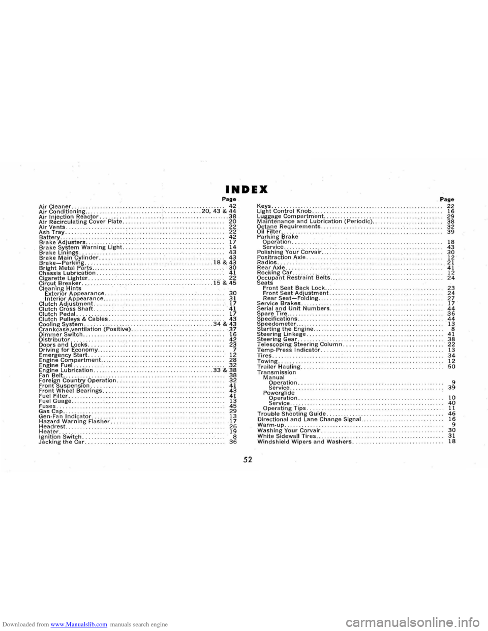
Downloaded from www.Manualslib.com manuals search engine INDEX Page Air Cleaner. . . . . . . . . .. , .. . . . . . . .. . . . . . . . . . . .......... 42 Air Conditioning.. ............ ... .... .• . . .20,43 & 44 Air Injection Reactor......... ........... . ... ... 38 Air Recirculating Cover Plate. . . . . . . . . . . .• . . . . .. . . . .. . . 20 Air Vents. . . . . . . . . . . . . . . . . . . . . . . 22 Ash Tray. ........ .. ... 22 Battery........... ............ ....•...•................. 42 Brake Adjusters...................... .. .. ... ............. 17 Brake System Warning Light. . ................. 14 Brake Lmings. . ....... ....... ........ ............... 43 Brake Main Cylinder.. ........... . ...... 43 Brake-Parking. . ............ .......... . .. 18 & 43 Bright Metal Parts..... .. ..................... '. 30 Chassis Lubrication. . . . . . . . . . . . . . 41 Cigarette Lighter. . . .. .... ... .. . . . .. .. " 22 Circut Brea ker. . . . . . ................. .. .............. 15 & 45 Cleaning Hints Exterior Appearance........ .... .... . ............ . 30 Interior Appearance.. ............... . ............. ........ 31 Clutch Adjustment......... 17 Clutch Cross Shaft. . . .. . . . . . . . ... .. . . 41 Clutch Pedal.. .. . .. .. .. .. . . .. .. . .. .. . 17 Clutch Pulleys & Cables..................... . 43 Cooling System. . . . . . . . . . . . . . . . . . ........ ....... 34 & 43 Crankcase.ventilation (Positive). 37 Dimmer Switch... .......... ..... 16 Distributor. . . . . . . 42 Doors and Locks. .. ..... .................. .• ................. 23 Driving for Economy..... ...... ...... 7 Emergency Start. . . . . . . . . . . . . . . . . . 12 Engine Compartment.... . . . . . . . . . . . . . . . . . . . .. .. . . 28 Engine Fuel. . . . . . . . . . . . . . . . . . . . . . . . . . . . . . . . . . . . . . . . . .. 32 Engine Lubrication. . . . . . . . . .. . . . .• . . . . . . . • . . . . . . .33& 38 Fan Belt........ .... ..................... ..... 38 Foreign Country Operation. .................. 32 Front Suspension. . . . . . . . . . . . . . ... . . . . . . . . . . . . . . . . . . . . . 41 Front Wheel Bearings.. . ............. .......... . 43 Fuel Filter. . . . . . . . . . . . . . . •. . . . . . . . . .. . . . . 41 Fuel Guage.. ............ 13 Fuses.. .. .. ... ...................... ..... 45 ~s~p.......... ~ Gen·Fan .Indicator........ 13 Hazard Warning Flasher. . 17 Headrest...... . . ....... ... .. ........ 26 Heater............................... ..... .. .......... 19 Ignition Switch. . . . . . . . . . . . . . . . . .. . . . . . . . . . . . . 8 Jacking the Car. . . . .. . . . . . . . . . . .. . . . . . . . . . . . . . . . . . . . . . . . . . . . . . .. 36
52
Keys............... . ......... .............. . Light Control Knob ...................... . . Luggage Compartment ................... . Maintenance and Lubrication (Periodic) .. Octane Requirements. . . . . ......... . Oil Filter .... ............ . Pa rking Bra ke Operation . ..................... . Service .......... ...... . Polishing Your Corvair... . . ... . . . . . .. . .........•. .... ........ Positraction Axle. . . ... ............... .. ...... .. .. .... . Radios. . . . .... . ........... . Rear Axle.... . . ...................................... . . Rocking Car .............. . Occupant Restraint Belts .. . . Seats Front Seat Back Lock ....... .•...... Front Seat Adjustment. Rear Seat-Folding ... Service Bra kes. . . . . . . . . .. . ......................... ... . Serial and Unit Numbers .......... .. . Spare Tire..... . .• ......... .................•.•. Specifications. . . . ................... ... .. .• ........ Speedometer ... .. ............... . Starting the Engine .... . Steering Lin kage ...... . Steering Gear ............... . Telescoping Steering Column. Temp·Press Indicator. Tires. Towing ..... Trailer Hauling. Transmission Manual Operation. ................ . ....... .. .... . Service ................... .. .. ...... .. . Powerglide Operation. Service ...... . Operating Tips ....... . Trouble Shooting Guide.......... . .............. ... . Directional and Lane Change Signal. . ....• ...•.... Warm·up... ............ . ....... .. ........... ... . Washing Your Corvair. . . ........ . White Sidewall Tires.. . . . . . . . . . . . . . . ......... .. . Windshield Wipers and Washers. . . .. .. .. .. .
Page 22 16 29 38 32 39
18 43 30 12 21 41 12 24
23 24 27 17 44 36 44 13 8 41 38 22 13 34 12 50
9 39
10 40 11 46 16 9 30 31 18