Page 489 of 885
FRONT AXLE AND SUSPENSION - Axle Hub
8. REMOVE AXLE HUB FROM
Using SST, remove the axle hub.
ssT 09950-2001 5
,. CAUTION: Cover the drive shaftrhl
( protect it from damage. (r':q
;; , +in f,rlve tl""ff\ii
!,ocr* d i t{" cIo*h to " .rr:'r,
g ra *e c* i t € ro*r ata ^4 1e.
REPLACEMENT OF FRONT AXLE HUB AND
WHEEL BEARING
(See page FA-7)
1. REMOVE DUST DEFLECTOR
Using a screwdriver, remove the dust deflector.
REMOVE INNER OIL SEAL FROM STEERING
KNUCKLE
Using SST, pull ou.t the oil seal.
ssr 09308-0001 0
REMOVE HOLE SNAP RING
Using snap ring pliers, remove the hole snap ring.
REMOVE THREE BOLTS
Remove the three bolts holding the disc brake dust
to the steering knuckle.
,..F. REMOVE AXLE HUQ FROM STEERING KNUCKLE€r:
Using SST, push off the axle hub.
ssT 09950-2001 5
6. REMOVE DISC BRAKE DUST COVER
7. REMOVE BEARING INNER RACE'(INSIDE)
2.
a
,{n.1n
t
3.
4.
fr
,f+
8. REMOVE. BEARTNG rlruen.qAbe (OUrSlOe)
Using 9ST, pull off the beaiing'inner race.
ssT 09950;20015 t r
Page 490 of 885

FA.1O
' -'v7:'
FRONT AXLE AND SUSPENSION - Axle Hub
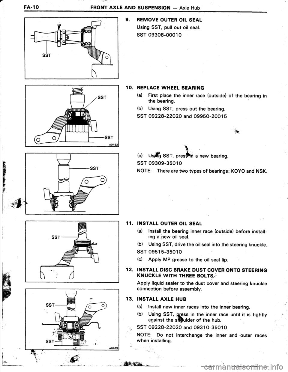
9. REMOVE OUTER OIL SEAL
Using SST, pull out oil seal.
ssT 09308-0001 0
1O. REPLACE WHEEL BEARING
h) First place the inner race (outside) of the bearing in
the bearing
(b) Using SST, press out the bearing.
SST 09228-22O2O and 09950-20015
(c) U$ilfi SST, prestffi a new bearing.
ssT 09309-3501 0
NOTE: There are two types of bearings; KOYO and NSK.
INSTALL OUTER OIL SEAL
h) Install the bearing inner race (outside) before install-
ing a pew oil seal.
(b) Using SST, drive the oil seal into the steering knuckle.
ssT 09515-35010
(c) Apply MP grease to the oit seal lip.
INSTALL DISC BRAKE DUST COVER ONTO STEERING
KNUCKLE WITH THREE BOLTS,
Apply liquid sealer to the dust cover and steering knuckle
connection before assembly.
INSTALL AXLE HUB
(a) Install new inner races into the inner bearing.
(b) Using SST, ggss in the inner race until it is tightty
against the sftlulder of the hub.
SST 09228-22O2O and O9310-35010
NOTE: Do not interchange the inner and outer races
when installing.
'.tfi
\
H
r
FE
11.
12.
13.
i
fr_, .,,iW;ffiqa-*L- L __
Page 492 of 885
'l
FA..12FRONT AXLE AND SUSPENSION - Axle Hub
(b) lnsert the bolts from the front side and align the
matchmarks of the camber adjust cam.
(c) Torque the bolts.
Torque: 1,450 kg-cm (105 ft-lb, 142 N'ml
5. INSTALL BRAKE CALIPER TO STEERING KNUCKLE
Torque the bolts.
Torque: 970 kg-cm (70 ft-lb, 95 N.ml
#
6. CONNECT TIE ROD END TO STEERING KNUCKLE
Torque the nut and secure it with a new cotter pin.
Torque: 6O0 kg:cm (43 ft-lb, 59 N.m)
'\i. i
tr,bWVii
i
TOROUE BEAfriG LOCK NUT AND INSTALL LOCK
NUT CAP AND;COTTER?IN
(a) Torqrle the lock nut wtrile depiUs.s.lng the brake pedal.
Torque: 1,900 kg-cm (137 ft-lb, f86 N.m)
(b) Install the lock nut cap affittsing plieib,.install a new
7.
cott*. pin.
8.
+
CHECK FRONT WHEEL ALIGNMENT f$6e page FA-3)'-*+***n,. it'., . .i .:)".4..,,'i".: "
Il.I
f,'l.
Page 498 of 885

I
FA-l8FRONT AXLE AND SUSPENSION - Front Drive Shaft
Length
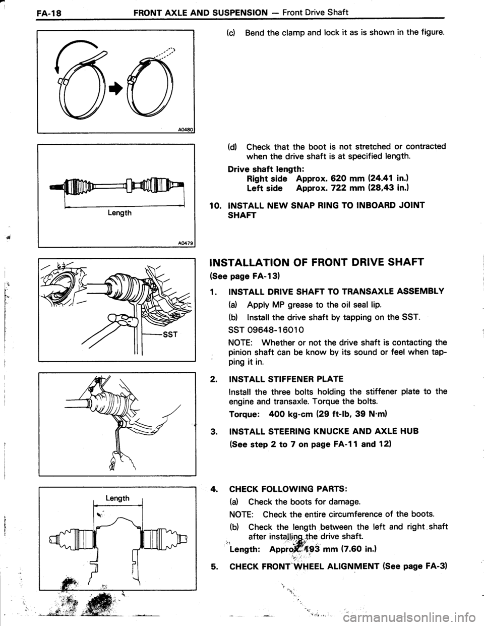
(c) Bend the clamp and lock it as is shown in the figure.
(d) Check that the boot is not stretched or contracted
when the drive shaft is at specified length.
Drive shaft length:
Right side Approx. 620 mm 124.41 in.l
Left side Approx. 722 mm (28,43 in.)
10. INSTALL NEW SNAP RING TO INBOARD JOINT
SHAFT
INSTALLATION OF FRONT DRIVE SHAFT
(See page FA-l3)
1. INSTALL DRIVE SHAFT TO TRANSAXLE ASSEMBLY
(a) Apply MP grease to the oil seal lip.
(b) lnstall the drive shaft by tapping on the SST.
ssT 09648-16010
NOTE: Whether or not the drive shaft is contacting the
pinion shaft can be know by its sound or feel when tap-
ping it in.
INSTALL STIFFENER PLATE
lnstall the three bolts holding the stiffener plate to the
engine and transaxle. Torque the bolts.
Torque: 400 kg-cm (29 ft-lb, 39 N'm)
INSTALL STEERING KNUCKE AND AXLE HUB
(See step 2 to 7 on page FA-l1 and 12)
4. CHECK FOLLOWING PARTS:
(d Check the boots for damage.
NOTE: Check the entire circumference of the boots.
(b) Check the length between the left and right shaft
after installinq,.the drive shaft.i": ' -|*itLength: Approjff{93 mm (7.60 in.)
5. CHECK FRONT"WHEEL ALIGNMENT (See page FA-31
2.
3.
"1.
Page 504 of 885

'l
FA.24FRONT AXLE AND SUSPENSION - Front Suspension
\7
3. INSPECT BALL JOINT FOR ROTATION CONDITION
(d Remove the balljoint. (See page FA-29)
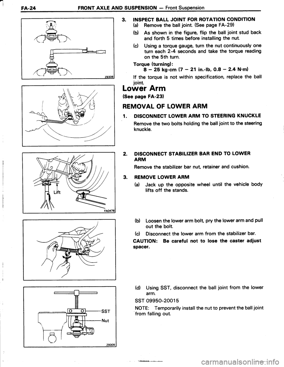
(b) As shown in the figure, flip the ball joint stud back
and forth 5 times before installing the nut
(d Using a torque gauge, turn the nut continuously one
turn each 2-4 seconds and take the torque reading
on the 5th turn.
Torque {turning}:
I - 25 kg-cm 17 - 21 in.-lb, 0.8 - 2'4 N'ml
lf the torque is not within specification, replace the ball
ioint.
Lower Arm
(See page FA-23)
REMOVAL OF LOWER ARM
1. DISCONNECT LOWER ARM TO STEERING KNUCKLE
Remove the two bolts holding the balljoint to the steering
knuckle.
2. DISCONNECT STABILIZER BAR END TO LOWER
ARM
Remove the stabilizer bar nut, retainer and cushion.
3. REMOVE LOWER ARM
(a) Jack up the opposite wheel until the vehicle body
lifts off the stands.
(b) Loosen the lower arm bolt, pry the lower arm and pull
out the bolt.
(d Disconnect the lower arm from the stabilizer bar.
CAUTTON: Be careful not to lose the caster adiust
spacer.
(d) Using SST, disconnect the ball joint from the lower
arm.
ssT 09950-2001 5
NOTE: Temporarily install the nut to prevent the balljoint
from falling out.
Page 508 of 885
a
FA.28FRONT AXLE AND SUSPENSION - Front Suspension
3. DISCONNECT BOTH STABILIZER BAR ENDS
TO LOWER ARM
4. REMOVE STABILIZER BAR
CAUTION: Be careful not to lose the spacer.
INSTALLATION OF STABILIZER BAR
1. INSTALL STABILIZER BAR END TO LOWER ARM
(d lnstall the spacer, retainer, rubber and collar as
shown in the figure.
(b) Finger tighten a new stabilizer bar nut.
2. INSTALL BRACKET TOGETHER WITH STABILIZER
BAR
Pry the bar forward and install the brackets.
Torque the bolts.
Torque: rt4o kg-cm (32 ft-lb,43 N.ml
3. TOROUE NUT HOLDING STABILIZER BAR TO LOWER
ARM
Torque: 1,O75 kg-cm (78 ft-lb, 105 N.ml
NOTE: Bounce the vehicle to stabilize the suspension
before torquing the stabilizer bar nut.
4. INSTALL ENGINE UNDER COVER
5. CHECK FRONT WHEEL ALIGNMENT (See page FA-3)
Page 514 of 885
-
RA-6 REAR AXLE AND SUSPENSION - Rear Axle Hub and Carrier (FWD)
3. DISCONNECT BRAKE TUBE FROM WHEEL CYLINDER
Using SST, disconnect the brake tube.
ssT 09751 -3601 1
4. REMOVE AXLE SHAFT
Remove the bolts holding the axle shaft to the carrier, and
remove the axle shaft and rear brake assembly.
5. REMOVE AXLE CARRIER
(d Remove the bolt and nut holding the axle carrier to
the strut rod.
(b) Remove the bolt and nut holding the axle carrier to
the No.1 suspension arm.
(d Remove the bolt and nut holding the axle carrier to
the No.2 suspension arm.
Page 515 of 885
REAR AXLE AND SUSPENSION - Rear Axle Hub and Carrier (FWD) RA-7
RAO233
(d) Remove the bolts and nuts holding the axle'carrier to
the shock absorber, and remove the axle carrier.
REPLACEMENT OF WHEEL BEARINGS
1. REMOVE INNER BEARING AND OIL SEAL
(a) Using a screwdriver, pry out the oil seal.
(b) Remove the inner bearing from the disc.
2, REMOVE BEARING OUTER RACES
Using SST, press out the bearing races.
SST 09608-1 601 0 and 09608-2001 1
3. INSTALL BEARING OUTER RACES
Using SST, carefully press in new bearing races.
SST 09608-16010 and 09608-2001 1
4. FILL INSIDE OF AXLE HUB AND CAP WITH MP
GREASE
L: