Page 1 of 20
STEERING SYSTEM
I---
SECTION ST
CONTENTS
STEERING SYSTEM . . . ... ..
STEERING COLUMN . . . .... ..
POWER STEERING SYSTEM -Checking - . ..
POWER STEERING GEAR AND LINKAGE
POWER STEERING
OIL PUMP . .. ... ..
SERVICE DATA AND SPECIFICATIONS (S D S ) . . . . . . . .
SPECIAL SERVICE TOOLS . .. .. ..
Refer to section MA for:
CHECKING WHEEL ALIGNMENT
Toe-in
Front wheel turning angle
BASIC MECHANICAL SYSTEM
Checking drive belts
. ST- 2
ST- 4
.. ST- 6
. . ST- 8
ST-14
. .. .. ST-17
. . . ST-20
Page 6 of 20

POWER STEERING SYSTEM -Checking
Fluid Level Check
Check the fluid level when the fluid IS cold.
Refer to MA section
Power Steering Pump
Belt Tension
Refer to MA section
Fluid Leakage Check
1 Run engine at idle speed or 1,000 rpm
Make sure temperature of fluid
in tank rises to
60 to 80°C (140 to 176°F).
2 Turn steering wheel to right-to-left several
times
3 Hold steering wheel at each "lock" position for
five seconds
and carefully check for fluid
leakage
CAUTION :
0 Do not hold steering wheel at "lock" position
for more than 15 seconds at a time.
0 If fluid leaks at connectors, replace O-ring (if
equipped) Do not overtighten connector as
this can damage O-ring and connector.
- Bleeding Hydraulic System -
1. Raise front end of vehicle until wheels clear
ground
2 While adding fluid, quickly turn steering wheel
fully to right and
left and lightly touch steering
stoppers.
Repeat steering wheel operation until fluid
level no
longer decreases
Repeat step 2 above
3. Start engine.
Hydraulic System Check
Before starting, check belt tension, driving pulley
and tire pressure. (Refer to MA section )
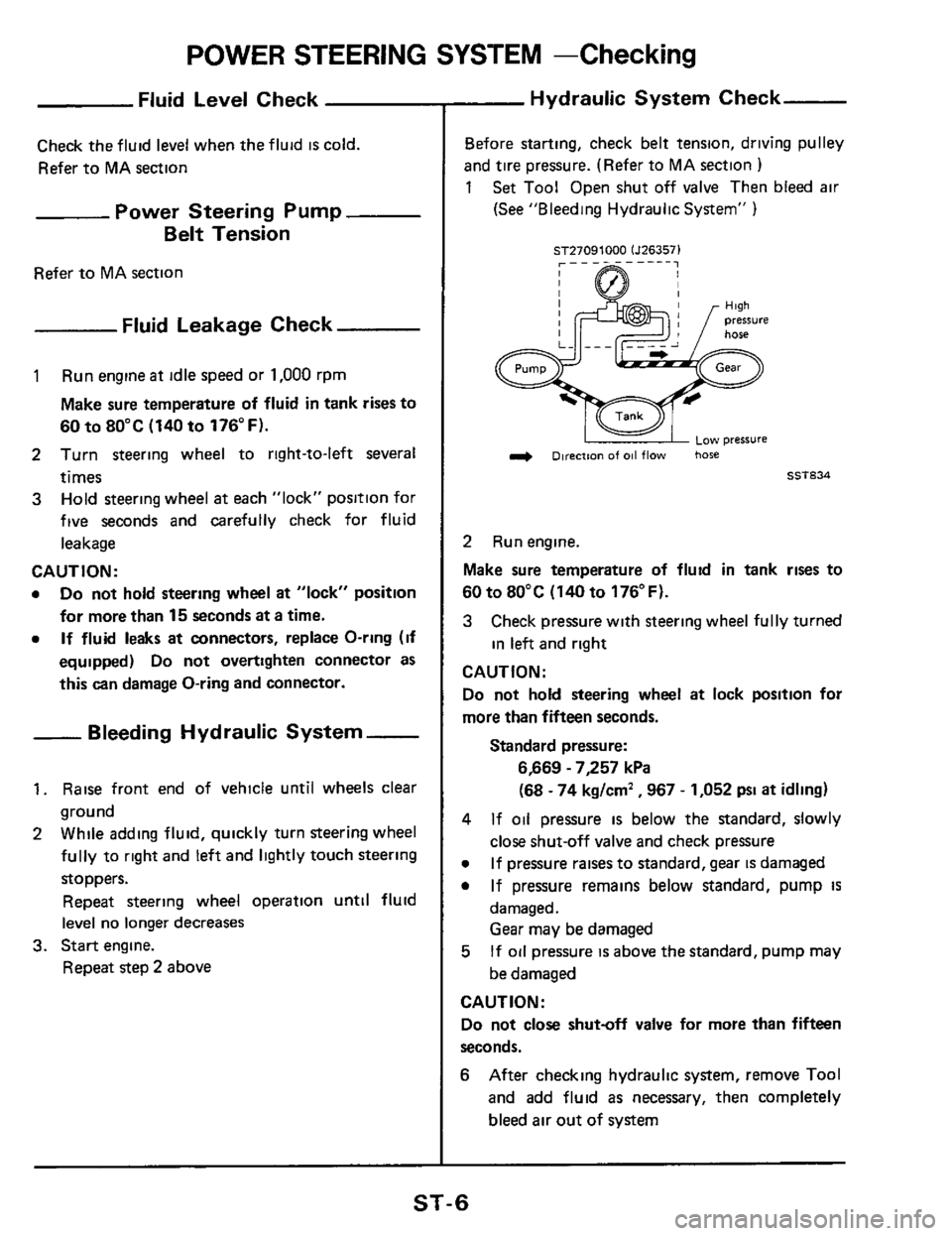
1 Set Tool Open shut off valve Then bled air
(See "Bleeding Hydraulic System" )
ST27091000 lJ263571
L 1 ow pressure
& Direction of 011 flow hose
ET834
2 Run engine.
Make sure temperature of fluid in tank rises to
60 to 80°C
(140 to 176°F).
3 Check pressure with steering wheel fully turned
in left and right
CAUTION:
Do not hold steering wheel at lock position for
more than fifteen seconds.
Standard pressure:
6,669 - 7,257 kPa
(68
- 74 kglcm' ,967 - 1,052 psi at idling)
4
0
0
If oil pressure is below the standard, slowly
close shut-off valve and check pressure
If pressure raises to standard, gear is damaged
If pressure remains below standard, pump
IS
damaged.
Gear may be damaged
If oil pressure is above the standard, pump may
be damaged 5
CAUTION:
Do not close shutoff valve for more than fifteen
seconds.
6 After checking hydraulic system, remove Tool
and add fluid as necessary, then completely
bleed
air out of system
ST-6
Page 14 of 20
![NISSAN 300ZX 1984 Z31 Steering System Workshop Manual POWER STEERING OIL PUMP
Connector Ispool cover1 Flexible hose
69-78
38.52 mi70-8051 1 A Washe2 Connector bolt
7 . I 0 9- 12 (09.12.65 -871 13 9.5 3,28 - 381
s,,rr,nn ",no.... I
36-51] --I ..I NISSAN 300ZX 1984 Z31 Steering System Workshop Manual POWER STEERING OIL PUMP
Connector Ispool cover1 Flexible hose
69-78
38.52 mi70-8051 1 A Washe2 Connector bolt
7 . I 0 9- 12 (09.12.65 -871 13 9.5 3,28 - 381
s,,rr,nn ",no.... I
36-51] --I ..I](/manual-img/5/578/w960_578-13.png)
POWER STEERING OIL PUMP
Connector Ispool cover1 Flexible hose
69-78
38.52 mi7'0-80'51 1 A Washe2 Connector bolt
7 . I 0 9- 12 (09.12.65 -871 13 9.5 3,28 - 381
s,,rr,nn ",no.... I
36-51] --I ..I.. r,r_
re switch (Non-turbocharged model)
Htgh-pressure ride
hydraultc
line pressure
1,961
- 2,942 kPa
(20.30 kg/cm' ,
Decreasing to aPProx
Turn ON
981 -2,942 kPa
(10 - 30 kg/cm' ,
142-427~511 1
42 I3 2 -43.23- 31)
L Pulley shaft (When assembling pulley shaft. be careful
not to damage oil seal lip1 seal
am
(41 31 -42 13.2 - 4.3, 23 - 311 (41 N m (kg-m. ft-lb)
fl Lubricatzon points (with automatic transmission fluid "Dexron Type") @ ~onotreu~
- Pre-disassembly Inspection
The power steering oil pump should be disassem-
bled only
d any of the following conditions are
ObSWVed.
Oil leak at the following points
SST126A
Deformed or damaged pulley
SST220A
Oil Pump Installation
mounting bracket
steering pump
(41 N m (kgm, ft-lbl
SST221A
m16-21 (1.6-21,
12.15)
After installing oil pump, adjust belt tension.
Refer to MA section.
ST-1 4
Page 17 of 20

SERVICE DATA AND SPECIFICATIONS (S.D.S.)
Turn of steering wheel (Lock to lock1
General Specifications
28
Steering gear type I [Power PR24S rteerlngl
I Collapsible
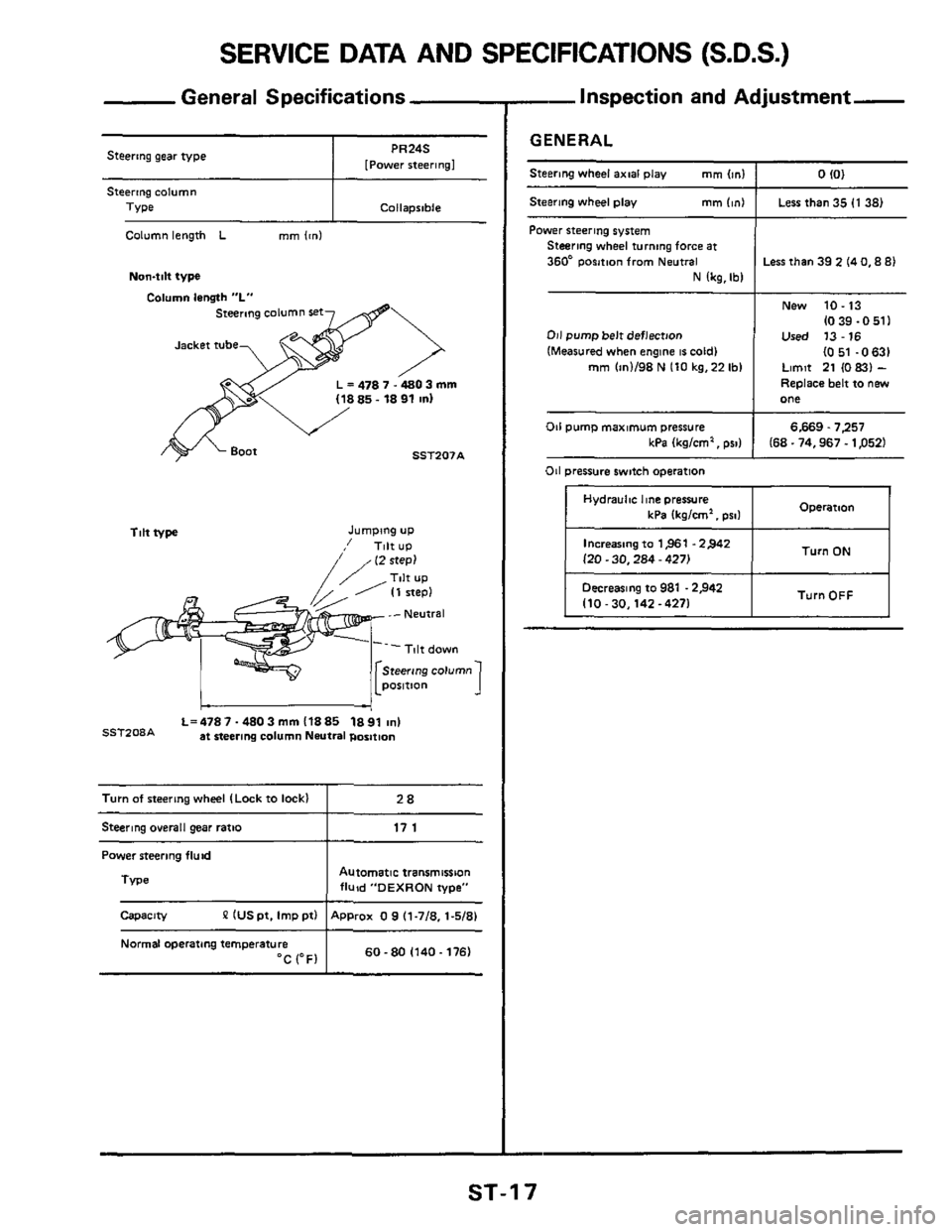
Column length L mm lcnl
Non4ilt type
Column lensth "L"
steermg column set
L = 478 7.4803 mm
SST207A
Tilt type Jumping UP
,' Tilt UP
L=4787-4803mml1885 1891 ~nl SSTZ08A at steering column Neutral position
Steering o~erall gear ratio I 17 1
Power steering fluid
Automatic transmission fluid "DEXRON type"
P IUS pt. Imp ptl ApProx 0 9 (1-718. 1-5/81
TVpe 1
Capacity
Normal operating temperature 60-80 (140.1761 "C (OF1
-Inspection and Adjustment-
GENERAL
Steering wheel axial play mm Im1 I 0 IO1
Steering wheel play mm (in1 I Less than 35 (1 38)
Power steering system Steering wheel turning force at
360* Position from Neutral
N lkg,Ibl
011 pump belt deflection
(Measured when engine 16 cold1 mm (in1198 N 110 kg.22 Ibl
Less than 39 2 14 0,8 81
New 10.13
(0 39.0 511 Used 13-16
I051 -0631 Limit 21 (0 831 -
Replace belt to new one
6.669.7257 kPa Ikglcm', PSI) I 168.74,967.1 p521
011 pump maximum pressure
011 pressure switch operation
Hydraulnc he pressure Operation kPa 1kglcm'. pro1 I
Increasing to 1,961 .2>42
l20.30,284 - 4271 Turn ON I
I TurnOFF I Decreasing to 981 .2,942 110-30.142-4271 I
ST-1 7