1984 NISSAN 300ZX torque
[x] Cancel search: torquePage 8 of 15
DIFFERENTIAL CARRIER (Type R200)
Note If values sigrufying H and D' are
not given, regard them as zero and
compute After assembly, check to
see that tooth contact
is correct If
not, readjust
For the tooth contact pattern, see
page PD-9
Note Phon height adjustment can
be made
in a ut of 1/1m mm
(4/10,000 m) by seleahg dm
0 05 mm (0 0020 in) or 0.07 mm
(0 0028 in) shm in above chart
4 Fit determined pinion height ad-
justing washer
in drive pinion, and
press
fit rear bearing inner race in it
using Base ST30901000
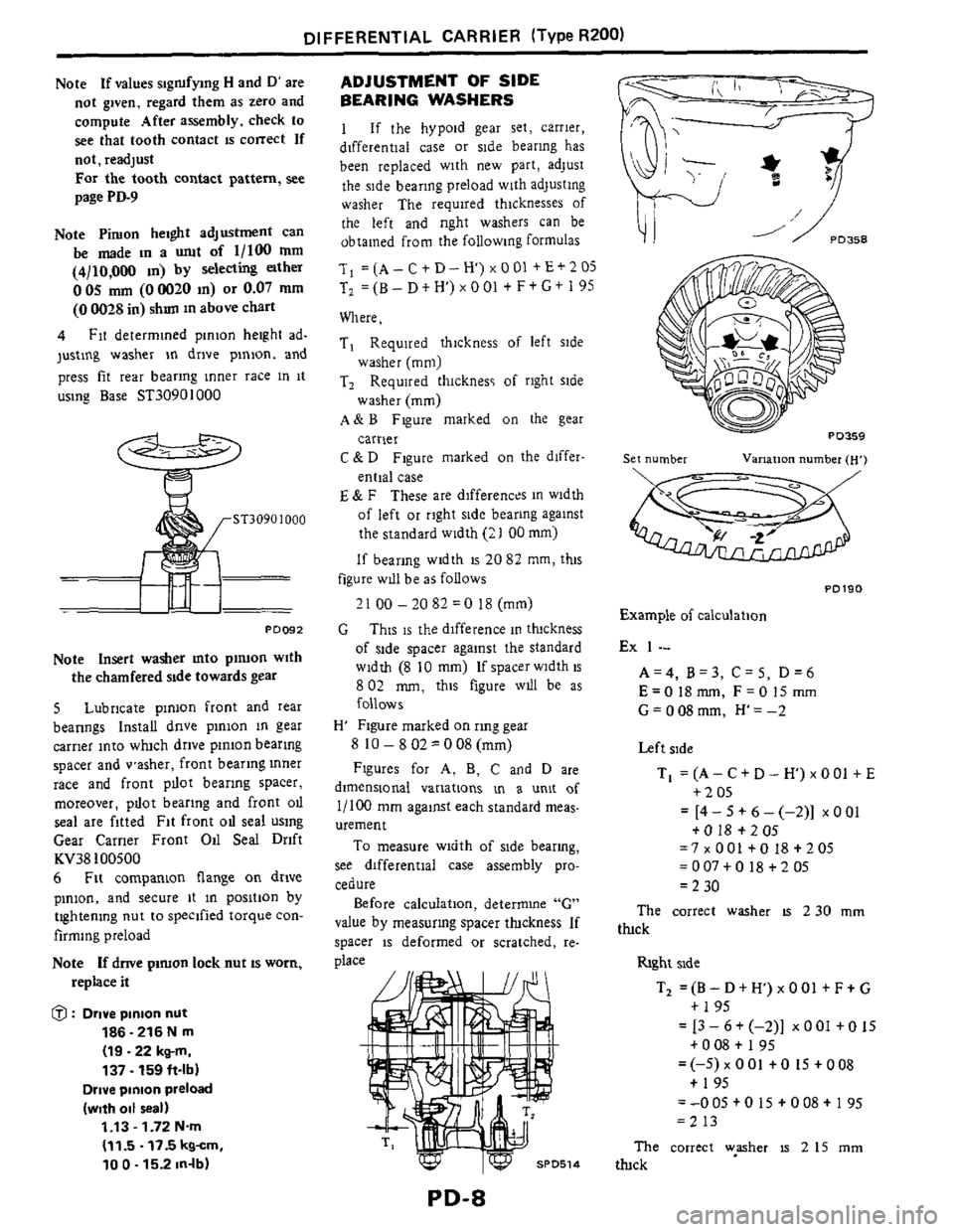
ST3090 1000
PO092
Note Insert washer mto pinion with
the chamfered side towards gear
5 Lubricate pinion front and rear
beanngs Install dnve pinion in gear
carrier into which drive pinion bearing
spacer and vasher, front bearing inner
race and front pllot bearing spacer,
moreover, pllot bearing and front
oll
seal are fitted Fit front OII seal using
Gear Carrier Front Oil Seal Drift
KV38
100500
6 Fit companion flange on drive
pinion, and secure it in position by
tightening
nut to specified torque con-
firming preload
Note If dnve pimon lock nut IS worn,
replace it
@ : Drive pinion nut
186 - 216 N rn
(19.22 kgm,
137.159 ft-lb)
Drive pinion preload
(with oil real)
1.13 - 1.72 N.m
(11.5.17.5 kgcm,
10 0 - 15.2 in-lb)
ADJUSTMENT OF SIDE
BEARING WASHERS
1 If the hypoid gear set, carrier,
differential case
or side bearing has
been replaced with new
part, adjust
the side bearing preload with adjusting
washer The required thicknesses of
the left and nght washers can be
obtained from the following formulas
T, =(A-C+D-H)xOOl +E+205
T2 =(B- D t H') x 0 01 t F+ G+ I 95
Where,
Ti Required thickness
of left side
washer (mm)
T2 Required thicknes of right side
washer
(mm)
A& B Figure marked on the gear
carrier
C & D Figure marked on the differ-
ential case
E & F These are differences in width
of left or right side bearing against
the standard width
(21 00 mm)
If bearing width is 20 82 mm, this
21 00 -2082 =O 18 (mm)
This is the difference in thickness
of side spacer against the standard
width (8
10 mm) If spacer width is
8 02 mm, this figure wdl be as
follows
H Figure marked on rmg gear
8
10 - 8 02 = 0 08 (mm)
Figures for A, B, C and D are
dimensional variations m a unit of
l/loO mm against each standard meas-
urement
To measure width of side bearing,
see differential case assembly pro-
cedure
Before calculation, deterrmne "G"
value by measurmg spacer thxkness If
spacer is deformed or scratched, re-
place
figure wlll he as follows
G
PD-8
Sei number Varlanon number (H)
PO190
Example of calculation
Ex
1 --
A=4, B=3, C=5, D=6
E=O18mm, F=OlSmm
G=O08mm, H'=-2
Left side
Ti =(A- Ct D- H)x00l +E
t205
+ 0 18 + 2 OS
- - [4-5+6-(-2)j ~001
=7 x 001 +O 18 + 2 05
= 007 t 0 18 +2 05
= 2 30
The correct washer IS 2 30 mm
thck
hght side
T, = (B - D t H) x 0 01 t F + G
t 195
+ 0 08 + I 95
+ 195
- -13-6+(-2)] xOOltO15
=(-5) x 001 +O IS t 008
=-005 +O 15 + 008+ 195
=213
The correct wpsher
IS 2 15 mm
Uuck
Page 9 of 15
DIFFERENTIAL CARRIER (Type R200)
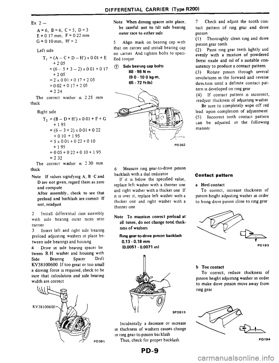
Ex 2 .--
A=6, B=6, C=5, D=3
E=O17mm, F-022mm
G=OIOmm, H'=2
Left side
Ti =(A - C t D - H') x 001 +E
=(6- 5 t 3 - 2) x 001 t 0 I7
=2 x 001 +O 17 t 2 05
= 0 02 t 0 I7 + 2 05
= 2 24
The correct washer is 2 25 mm
+ 2 05
+ 2 05
thck
fight side
T, = (B- Dt H') x 001 f F+ G
= (6 - 3 t 2) x 001 f 0 22
= 5 x 0 01 + 0 22 + 0 IO
=005+022tO IO+ 195
= 2 32
t 195
+010+195
t 195
The correct washer is 2 30 mm
thick
Note
If values signifying A, B C and
Dare not gwen, regard them as zero
and compute After assembly, check to
see that
preload and backlash are correct
If
not, readjusl
2 Install differential case assembly
with side bearing outer races into
carrier
3 Insert left and right side bearing
preload adjusting washers
in place be.
tween side bearings and hocsing
4 Drive in side bearing spacer be
tween
R H washer and housmg with
Side Bearing Spacer Drift
KV38100600
If too great or too small
a dnving force
is required, check to be
sure that calculation and side bearing
width are correct
Note When driving spacer into place,
be careful not
to tilt side bearing
outer race
to either side
5 Align mark on bearing cap with
that on carrier and install bearing cap
on Larrier And tighten bolts to speci-
fied torque
@ Side bearing cap bolts
88-98Nm
65 - 72 ft-lb)
(9 0.10 0 kg-m.
PD362
6 Measure ring gear-to-drive pinion
backlash with a dial indicator
If it IS below the specified value,
replace left washer with a thinner one
and right washer with
a thicker one If
it
is over it, replace left washer with a
ttucker one and right washer with a
thinner one
Note To maintain correct preload at
all tunes, do not change total thick-
ness
of washers
Ring gear-todrive pinion backlash
0.13.0.18 mm
(0.0051 .0.0071 in)
SPD513
Incidentally a decrease or increase
in thickness
of washers causes change
in ring gear-to-pinion ba( klash
Thus, check for proprr backldsh
PD-9
7 Check and adjust the tooth con.
tact pattern
of ring gear and drive
pinion
(I) Thoroughly clean ring and drive
pinion gear teeth
(2) Paint ring gear teeth lightly and
evenly with a mixture of powdered
ferric oxide and oil of a suitable con-
sistency to produce a contact pattern
(3) Rotate pinion through several
revolutions in the forward and reverse
direLtion until a definite contact pat-
tern is developed
on ring gear
(4) If contact pattern is incorrect,
readjust thickness
of adjusting washer
Be sure to completely wipe off red
lead upon completion
of adjustment
(5) Incorrect teeth contact pattern
'an be adjusted in the following
manner
Contact pattern
a Heel contact
To correct, increase thickness of
pinion height adjusting washer in order
to bring drive pinion close to ring gear
PO193
b Toecontact
To correct, reduce thickness of
pinion height adjusting washer in order
to make drive pinion move away from
ring gear
PD194
Page 10 of 15
DIFFERENTIAL CARRIER (Type R200)
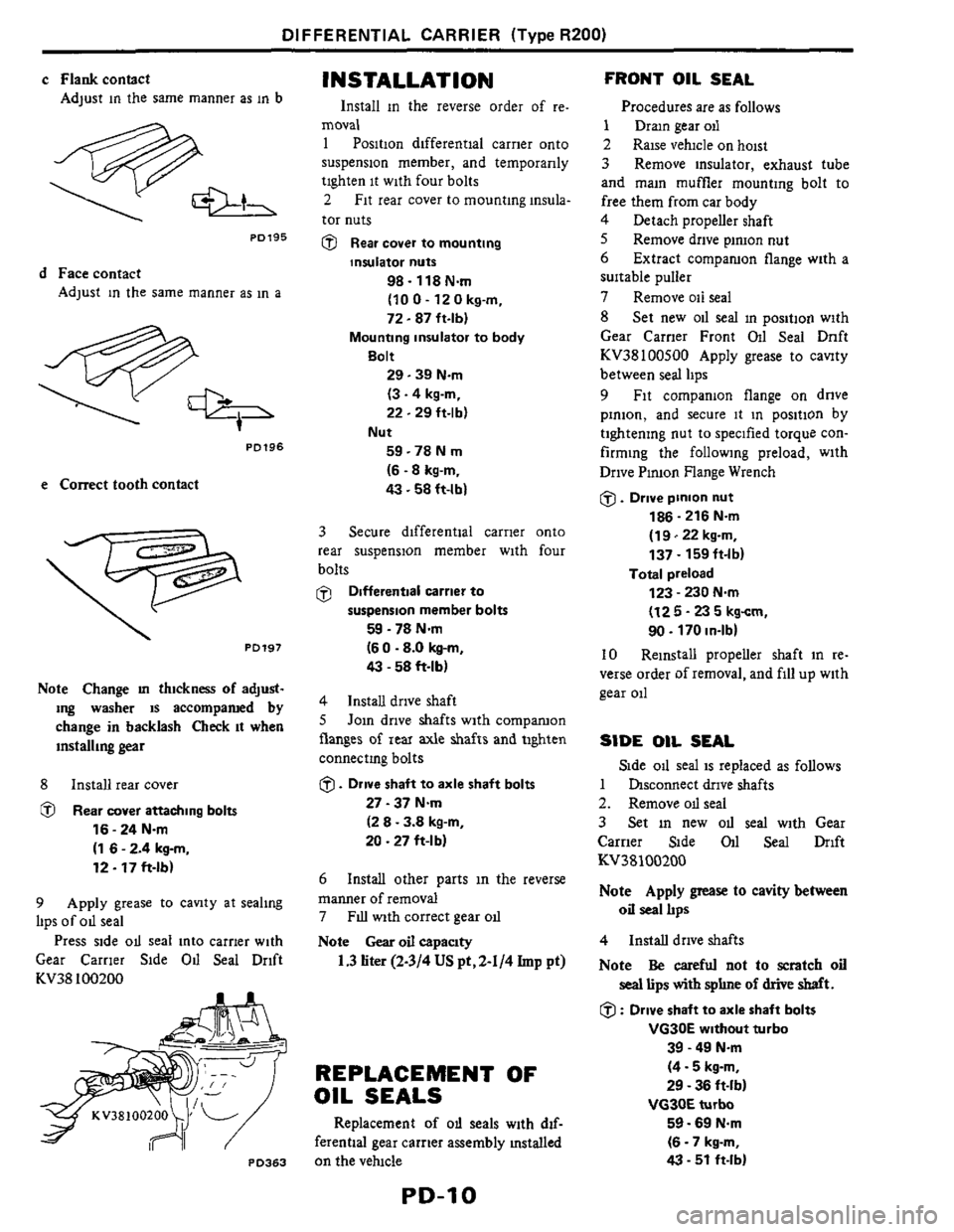
c Flankcontact
Adjust in the same manner as in b
PO195
d Face contact
Adjust in the same manner as in a
PD196
e Correct tooth contact
. PD197
Note Change m thickness of adjust-
ing washer
is accompamd by
change in backlash Check it when
installing
gear
8 Install rear cover
@ Rear cover attaching bolts
16 - 24 Nm
(1 6 - 2.4 kg-m,
12.17 ft-lb)
9 Apply grease to cavity at sealing
lips of od seal
Press side od seal into carrier with
Gear Carrier Side
Od Seal Drift
KV38 100200
PO363
INSTALLATION
Install in the reverse order of re.
moval
1 Position differential carrier onto
suspension member, and temporarily
tighten
it with four bolts
2 Fit rear cover to mounting insula-
tor nuts
@ Rear cover to mounting
insulator nuts
98.118 Nm
(10 0 - 12 0 kg-m,
72.87 ft-lbl
Mounting insulator to body
Bolt
29.39 Nm
(3.4 kg-m,
22.29 ft-lbl
59 -78 N m
(6.8 kg-m,
43.58 ft-lb)
Nut
3 Secure differential carrier onto
rear suspension member with four
bolts
@ Differentlal carrier to
59 - 78 Nm
(6 0 .8.0 kg-m,
43 - 58 ft-lbl
suspension member bolts
4 Install drive shaft
8 Join drive shafts with comparuon
flanges
of rear axle shafts and tighten
connectmg bolts
0. Drive shaft to axle shaft bolts
27 - 37 Nm
(2 8 - 3.8 kg-m,
20 .27 ft-l b)
6
manner of removal
7
Note Gear oil capaclty
Install other parts in the reverse
FIU with correct gear od
1.3liter(2-3/4USpt,2-1/4Imp pt)
REPLACEMENT OF
OIL SEALS
Replacement of od seals with dif-
ferential gear carrier assembly mstalled
on the velucle
FRONT OIL SEAL
Procedures are as follows
1 Dram gear oil
2 Raise vehicle on hoist
3 Remove insulator, exhaust tube
and main muffler mounting bolt to
free them from car body
4 Detach propeller shaft
8 Remove drive piruon nut
6
suitable puller
7 Remove oil seal
8 Set new oil seal in position with
Gear Carner Front Oil Seal Dnft
KV38100800 Apply grease to canty
between seal lips
9 Fit companion flange on dnve
pinion, and secure it in position by
tightening nut to specified torque con-
firming the following preload, with
Drive Pinion Flange Wrench
0. Drive pinion nut
186 - 216 N.m
(1 9122 kg-m,
137
- 159ft-lb)
123 - 230 Nm
(12 5 - 23 5 kgcm,
90. 170 in-lbl
Extract comparuon flange with a
Total preload
10 Reinstall propeller shaft in re-
verse order of removal, and fill up with
gear oil
SIDE OIL SEAL
1 hsconnect drive shafts
2. Remove od seal
3 Set in new OII seal with Gear
Carrier Side
011 Seal Drift
KV38100200
Note Apply grease to cavity between
oil seal IIps
Side od seal is replaced as follows
4 Install drive shafts
Note
Be careful not to scratch oil
seal lips with sphne of drive shaft.
0 : Drive shaft to axle shaft bolts
39 - 49 N.m
(4.5 kg-m,
29 - 36 ft-lb)
VG3OE turbo
59.69 Nm
(6 - 7 kg-m,
43 - 51 ft-lb)
VG30E without turbo
Page 11 of 15
SERVICE DATA AND SPECIFICATIONS (S.D.S.)
Applied model
Propeller shaft model
Propeller Shaft
GENERAL SPECIFICATIONS Unit mm On1
VG30E turbo VG30E wthout turbo VG30E turbo VG30E without turbo
MIT AIT M/T AIT MIT Am MIT A/T
ZS71A
2 seatei
Type of journal bearing
I 2+2 seater
Shell type lnon-dlrarrembly type)
Shaft length (Spider to rpiderl 665 126 181 685 126 97)
Number Of Joints I 2
650 (25 591 715 I28 151 865 134 061 885 (34 84) 850 133 461 915 136 02)
Couplmg method with traksion I Sleeve type ~
~~
Ring gear pitch
diameter
Gear
ratio
Number of teeth [Ring gear1Drwe pmonl
011 capacity lapprox 1
mm In)
Q IUS PZ, Imp gtl
Dlrtance between yokes I 71 12 80) ~
200 (7 871
3 700 3 545
37/10 3911
1
1 3 12-3/4, 2-1/41
Shaft outer diameter I 75 12 951
SERVICE DATA Unit mm (cnl
Model 2S71A
Propeller shaft runout llmlt 0 6 IO 0241
Journal axial Play 0 101
Differeni
GENERAL SPECIFICATIONS
wthout turbo
F~nal dwe model I R200
TIGHTENING TORQUE ~~~
~ ~
U"lt Nm kg-m ft-lb
Shaft to Companion 39-44 40-45 29 33
flange bolts
11 Carrier
SERVICE DATA
Final drive model WOO
Dr~ve ptnion beartog preload
adjusting method Adiumng spacer and washer
1 13.1 72
(115-175,100-1521
Drwe pmon preload
IWlth
front 011 seal1
N m lkgim, In-lbl
Drive pinion preload IWithout front 011 real) 1 0- 1 3 (10- 13,s 7- 11 31 N m Ikgim. in-lbl -
Total preload 1 23 - 2 30
I12
5 - 23 5. 10 9- 2041 N m Ikgcm, dbl -
Side bearing adJustmg method Shim
Backlash
0 13.0 18 10 0051 - 0 00711 Drive pinIan to ring gear rnm Iinl
Side gear to pinion mate gear
(Clearance between ride gear to differential carel mm Id Less than 0 15 (0 00591 ~
~
Ring gear runout Imit mm Iinl Less than 0 08 IO 0031 1
PD-11
Page 12 of 15
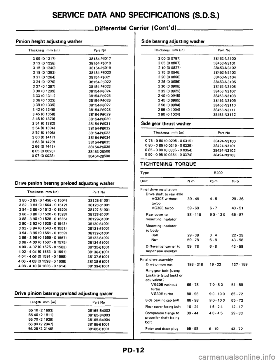
SERVICE DATA AND SPECIFICATIONS (S.D.S.)
Differential c
Pinion height adjusting washer
Thickness mm linl Part No
3 09 IO 12171 38154.P6017
3 12
10 1228) 38154P6018
3 15
(0 1240) 38154.P6019
3 18
IO 12521 38154P6020
3 21
IO 12641 38154.P6021
3 24 10 1276) 381 54-P6022
3 27
(0 12871 38154.P6023
3 30
IO 12991 38154-P6024
3331013111 38154-P6025
3 36
IO 1323) 38154-Pti026
3 39 IO 13351 38154.P6027
3 42 10 13461
381 54-P6028
3 45
IO 1358) 38154.P6029
3
48 (0 13701 38154-P6030
3 51 10 13821
381 54 P6031
3
54 IO 13941 38154-P6032
3 57
IO 14061 38154P6033
3
60 (0 1417) 38154.P6034
3 63
IO 14291 38154.P6035
3 66 (0 1441) 381 54-P6036
0 05 10 00201 38453-28500 0 07 (0 00281 38454-28600
Drive pinion bearing preload adjusting washer
Thlcknerr mm (In1 Part No
3 80 -3 82 10 1496 -0 15041 3812561001
3 82.3 84 10 1504- 0 15121 38126-61001
3 84.3
86 IO 1512 -0 15201 38127-61001
3 86.3 88 (0 1520-0 1528) 381 286 100 1
3 88 - 3 90 10 1528-0 15351 381 2961001
390-392101535-01543) 38130-61001
3 92.3 94
(0 1543 -0 15511 38131-61001
3
94 - 3 96 10 1551 .O 15591 3813261001
3 96.3 98
IO 1559-0 15671 3813361001
3 98
- 4 00 IO 1567 - 0 15751 381 34-61001
4
00 - 4 02 IO 1575-0 1583) 3813561001
4
02 - 4 04 10 1583 - 0 15911 3813661001
404-4
06 IO 1591 -0 1598) 3813761001
4
06 - 408 IO 1598-0 16061 38138-61001
408-410101606-01614) 38139-61001
Drive pinion bearing preload adjusting spacer
Length mm Id Part No
55 10 (2 16931 55 40 I2 181 11
55 70 I2 1929)
56 00 I2 2047) 56 25 I2 21461
3816564002
38165-64003
3816584004
381 65-61001
3816661001
rrier (Cont'd)
Side bearing adjusting washer
Thickness mm l>nl Part No
2 00 IO 07871 38453-N3100
38453-N3101 2 05 IO 08071 2 10 (0 08271 38453.N3102
2 15 IO 08461 38453-N3103
2 20 10 08661 38453-N3104 2 25 IO 08861 38453.N3105
2 30 IO 09061 38453.N3106
2 35 IO 09251
38453 N3107
2 40 10 09451 38453-N3108
2 45 IO 09651 38453.N3109
2 50 10 09841 38453.N3110
2 55 10 10041 38453.N3111
38453-N3112 2 60 IO 10241
Side gear thrust washer ~ ~~
Thickness mm lint Part No
0 75.0 80 IO 0295.0
0315) 38424.N3100
080-085100315-003351 38424-N3101
0 85.0 90 IO 0335.0 0354) 38424-N3102 0 90.0 95 IO 0354 - 0 03741 38424.N3103
TIGHTENING TORQUE
Type R200
Unlt Nm kg-m ft-lb
Final drive installation
Drive shaft to rear axle
VG30E without 39.49 4-5 29.36
turbo
VG30E turbo 59-69 6-7 43
- 51
Rear cover to 88-118 90-120 65-87
mounting lniulator
Mounting insulator
to body
Bolt 29-39 3 4 22 - 29
Nut 59-78
6-8 43.58
Dlfferentjal carrier to 59 78
6. 8 43.58 suspension member
Final drive assembly
Drive ptnm nut 186-216 19-22 137 - 159
Ring gear bolt [using
Locktite lrtud lock1
or
equivalent1
VG30E without 69 - 78 7 0.8 0 51 .58 turbo
VG30E turbo 88-98 90-100 65-72
Side bearing cap bolt 88 - 98 9 0.10 0 65 - 72
Rear cover fixing bolt 16. 24 16-24 12-17
Companm flange to 39.44 40-45 29-33 propeller shaft fixing
bait
Filler and drat" plug 59 - 98 6 - 10 43 - 72
PD-12
Page 13 of 15
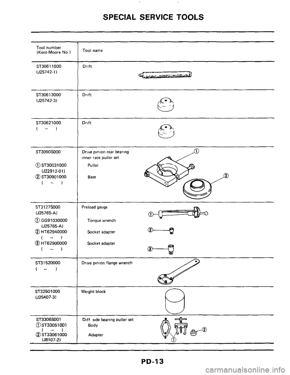
SPECIAL SERVICE TOOLS
Tool number
(Kent-Moore No 1
ST30611000
(J25742-1)
ST30613000
lJ25742-3)
ST30621000
(-)
ST3090SOOO
@ ST30031000
(J22912-011
@ ST30901 000
(-1
ST3127S000
(J25765-A)
@ GG91030000
(J25765-A)
@ HT62940000
(-1
@ HT62900000
(-1 ~ ~~
ST31
520000
(- 1
ST32501000
(J25407.3)
ST3306SJ01
@ST33051
001 1-1
@~T33061000 (58107-21
Tool name
Drift ~~ ~
Drift
Drift
P Drive pinion
rear bearing
inner race puller set
Puller
Base
Preload gauge
Torque wrench
Socket adapter -3
Socket adapter
Drive pinion flange wrench
Weight block
Diff side bearing puller set
Body
Adapter
PD-13