Page 1 of 34
MANUAL TRANSMISSION
I
CONTENTS
REMOVAL AND INSTALLATION ...... ...... .... MT-2
ON-VEHICLE SERVICE
. . .. .. _. MT- 3
MAJOR OVERHAUL - FS5W71C. ... ...... ........ Mi- 4
DISASSEMBLY - FS5W71C ....... .. MT- 7
REPAIR FOR COMPONENT PARTS-FS5W71C ..... MT- a
ASSEMBLY - FS5W71C ...... , . . MT-18
5-SPEED TRANSMISSION [Model BW T-5 (FS5R90AIl
... MT-20
Rear extension
.. ... ..... ...... MT-23
Case cover
. . ......... ......... MT-23
Transmission case
. . ... .... MT-24
Gearstkshafts
.... .. .. .. ... MT-27
Replacement of
oil seals .... ..... MT-28
Replacement
of bearings . .I. ....... . MT-29
SPECIAL SERVICE TOOLS .... MT-33
SERVICE DATA AND SPECIFICATIONS (S D S ) .. MT-30
Page 2 of 34
REMOVAL AND INSTALLATION
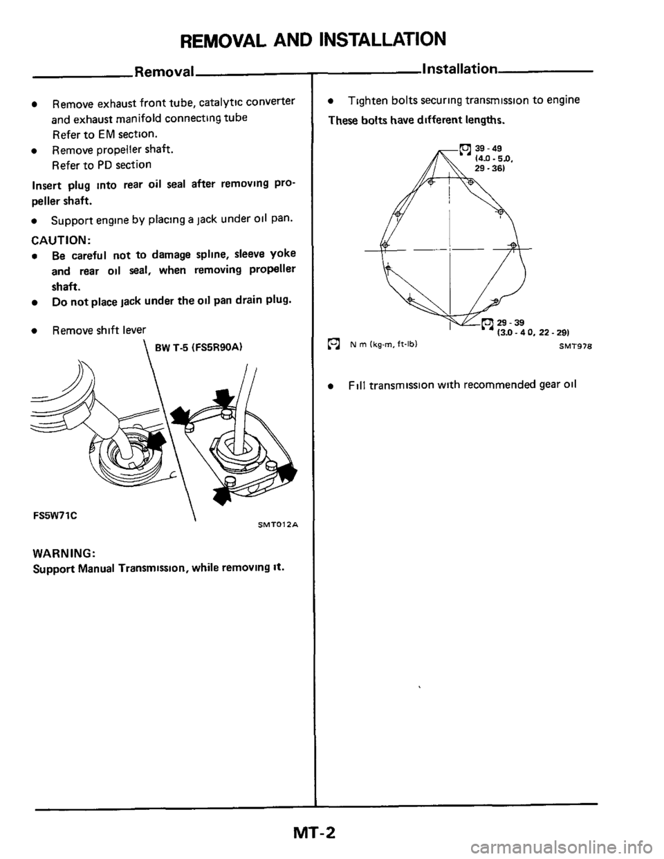
Remove exhaust front tube, catalytic converter
and exhaust manifold connecting tube
Refer to
EM section.
a Remove propeller shaft.
Refer to
PD section
Insert plug into rear oil seal after removing pro-
peller shaft.
a Support engine by placing a jack under oil pan.
CAUTION:
a Be careful not to damage spline, sleeve yoke
and rear oil seal, when removing propeller
shaft.
Do not place lack under the oil pan drain plug.
a Remove shift lever
BW T-5 (FS5R90A)
SMTOlZA FS5W71C
WARNING:
Support Manual Transmission, while removing It.
Installation
a
These bolts have different lengths.
Tighten bolts securing transmission to engine
22.291
SMT978
Fill transmission with recommended gear oil
MT-2
Page 7 of 34
DlSASSEMBLY-IFS5W71C
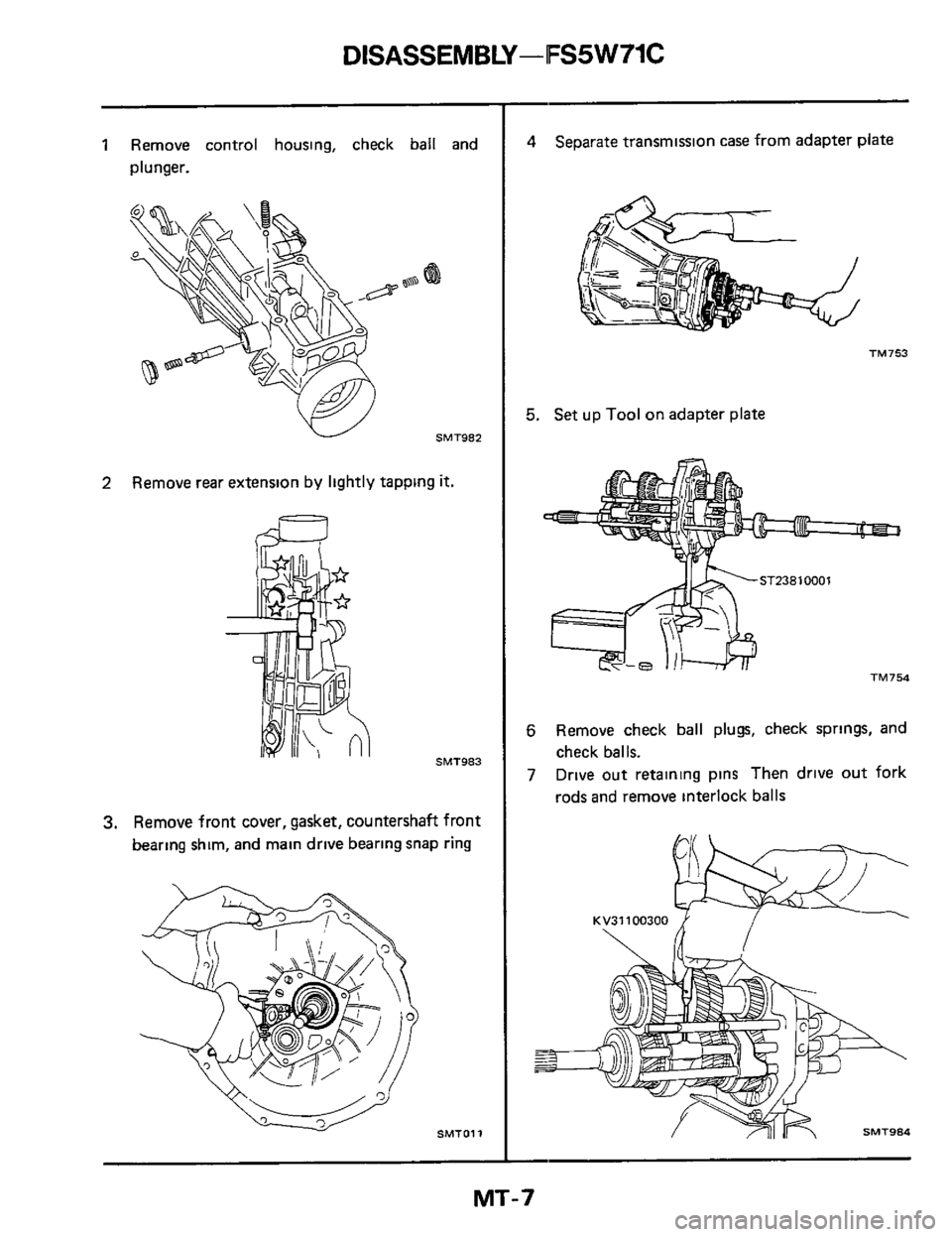
1 Remove control housing, check ball and
plunger.
W SMT982
2 Remove rear extension by lightly tapping it.
60
SMT983
3. Remove front cover, gasket, countershaft front
bearing shim, and main drive bearing snap ring
SMTOll
4 Separate transmission case from adapter plate
TM753
5. Set up Tool on adapter plate
TM754
6 Remove check ball plugs, check springs, and
7 Drive out retaining pins Then drive out fork
check balls.
rods and remove interlock balls
MT-7
Page 18 of 34
ASSEMBLY -FS5 W71C
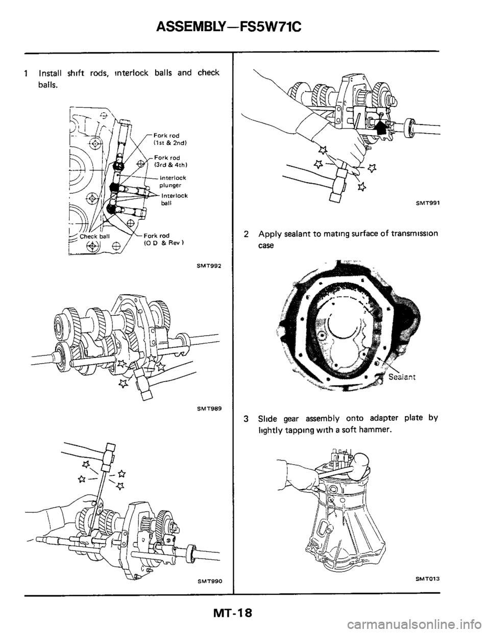
1 Install shift rods, interlock balls and check
balls.
SMT992
SMT989
SMT990
U SMT991
2 Apply sealant to mating surface of transmission
case
3 Slide gear assembly onto adapter plate by
lightly tapping with a soft hammer.
SMT013
MT-18
Page 20 of 34
![NISSAN 300ZX 1984 Z31 Manual Transmission Workshop Manual 5-SPEED TRANSMISSION [Model: BW T-5 (FS5R90A)l
5-SPEED TRANSMISSION [Model : BW T-5 (FS5R90A)]
Case. shift cover, extension housing
Tightening torque [N m 1kg-m.ff-lbll
2 Neutral witch 20 - 29 1](/manual-img/5/575/w960_575-19.png "NISSAN 300ZX 1984 Z31 Manual Transmission Workshop Manual 5-SPEED TRANSMISSION [Model: BW T-5 (FS5R90A)l
5-SPEED TRANSMISSION [Model : BW T-5 (FS5R90A)]
Case. shift cover, extension housing
Tightening torque [N m 1kg-m.ff-lbll
2 Neutral witch 20 - 29 1")
5-SPEED TRANSMISSION [Model: BW T-5 (FS5R90A)l
5-SPEED TRANSMISSION [Model : BW T-5 (FS5R90A)]
Case. shift cover, extension housing
Tightening torque [N m 1kg-m.ff-lbll
2 Neutral witch 20 - 29 12 0.3 0, 14 - 221
4 Hex head bolt 8.1 - 14 7 10 83 - 1 5,6.0.10 81 5 Hex head shoulder bolt 8 1 - 14 7 IO 83.1 5.6 0 -
20 Control housing rrew 15 - 27 11 5 - 2 8.11 - 201
31 Hex head flanged bolt 27 - 62 12.8.6 3,20 .461
36 Pivot pin 21 -33 12 1 -34, 15-25)
37 Bad-up lamp
witch 17 - 24 11.7 .2.4.12.171
Drain plug 20 .34 (2.0.3 5, 14 - 251 SMT846
1 Casecwer
2 Neutralswltch
3 Wmgcbp 4 Hexheadbolt
5 Hex head shoulder bolt
6h 7 0-nng
8 Welshplug
9 Shfter shaft 10 3-4 Mtfork 11 swt fork msert
12 Selector plate 13 Control seiector ann
14 Interlock plate I5 I-Zshrft fork
16 Boot retamer
10 81
17 Boot 18 Boot retamer
19 Control Iever/housng assembly 20 Control houmg screw
21 Dampersleeve
22 Offset lever 23 Spmg-pm
24 Detentspmg
25 Ball
26 Extennon housmg Not sewiced 27 Detent & guide plate ! separately
28 Bushmg
29 Cup plug 30 01Iseal
31 Hex head flanged bolt
32 Breath
Mi-20
33 Case 34 Magnet 35 cllp 36 Plvatpm
37 Back-up lamp swtch
38 Welsh plug
39 Plpeplug 40 5th and reverse relay lever
42 5th and ~everse rhrft rad Not sernced
separately
Not se~ced
separately
41 Retammgmg
43 Roller cam and pm
44 Reverse duft fork
4$ Roller cam and pm
46 5th gear duft fork 47 Insert
48 Spring-pin 49 sprmg
!
Page 21 of 34
5SPEED TRANSMISSION [Model: BW T-5 (FS5R90A)I
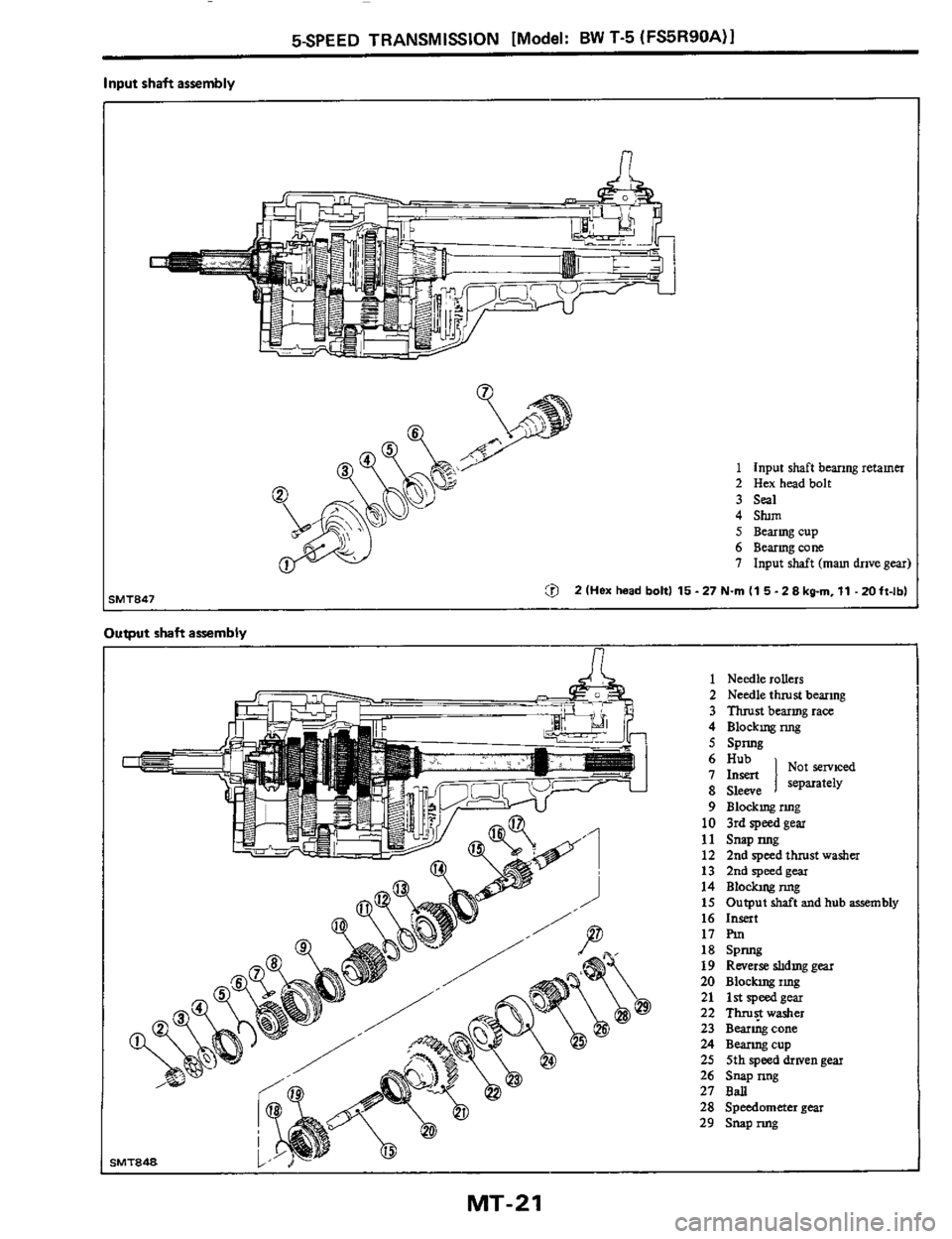
Input shaft assembly
n
1 Input shaft bearmg retamer 2 Hex headbolt
3
Seal
4 Stum 5 Bearmgcup
6 Bearmgcone
7 Input shaft
(mam drive gear)
ZlHex head bolt1 15-27N.rnl15-Z8kgrn,11 -20ft-lbl
Output shaft assembly
n
iMT848
1 Needle rollers
2 Needle thrust bearmg
3 Thrustbearmgrace
4 Blockngnng
5 SPnng
9 Blo&ngnng
10 3rdspeedgea1
12 2nd speed thrust washer
13 Zndspeedgear
14 Blockngnng
15 Output
shaft and hub assembly
16 Insert
17
F’m
18 SPW
19 Reverse shdmg gear
20 Block~ngimg
21 lstspeedgear
22 Thm$washer
23 Bearmgcone
24 Beanngcup
25 5th speed &wen gear
26 S~pmg
27 BaJ
28 Speedometer
gear
29 S~pnng
11 SMP IUlg
MT-21
Page 22 of 34
5SPEED TRANSMISSION [Model: BW T-5 (FS5R90A)l -1
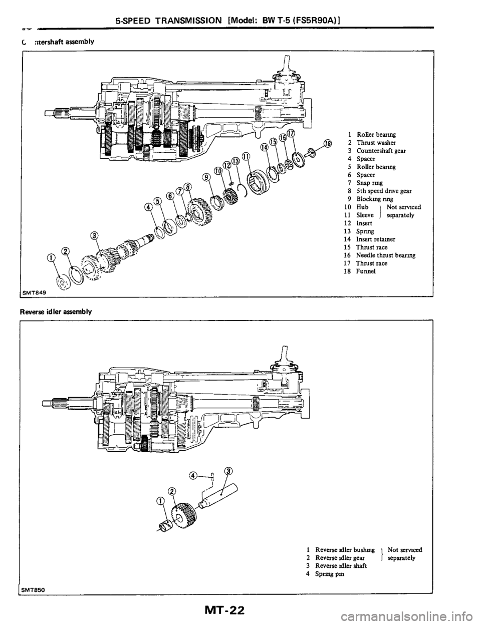
C aterrhaft assembly
1 Rollerbearmg
2 Thrustwasha
3 Countershaft gear
4 Spacer
5 Rollerbeanng
6 Spacer I snapnng
8 5th speed drlve gear
9 Blockrngrmg
10 Hub Notsmced
11 Sleeve 1 separately 12 lnmt
14 Insert retamer
16 Needle thrust bearmg
18 Funnel
13 SP~
IS Thrust race
17 Thrustrace
Reverse idler assembly
n
1 Reverse idler bushmg Not ~e~ced
2 Rwase idler gear
3 Rwersetdler shaft 1 separately
4 Spnngpm
UT850
MT-22
Page 23 of 34
5SPEED TRANSMISSION [Model: BW T-5 (FS5R90A)l
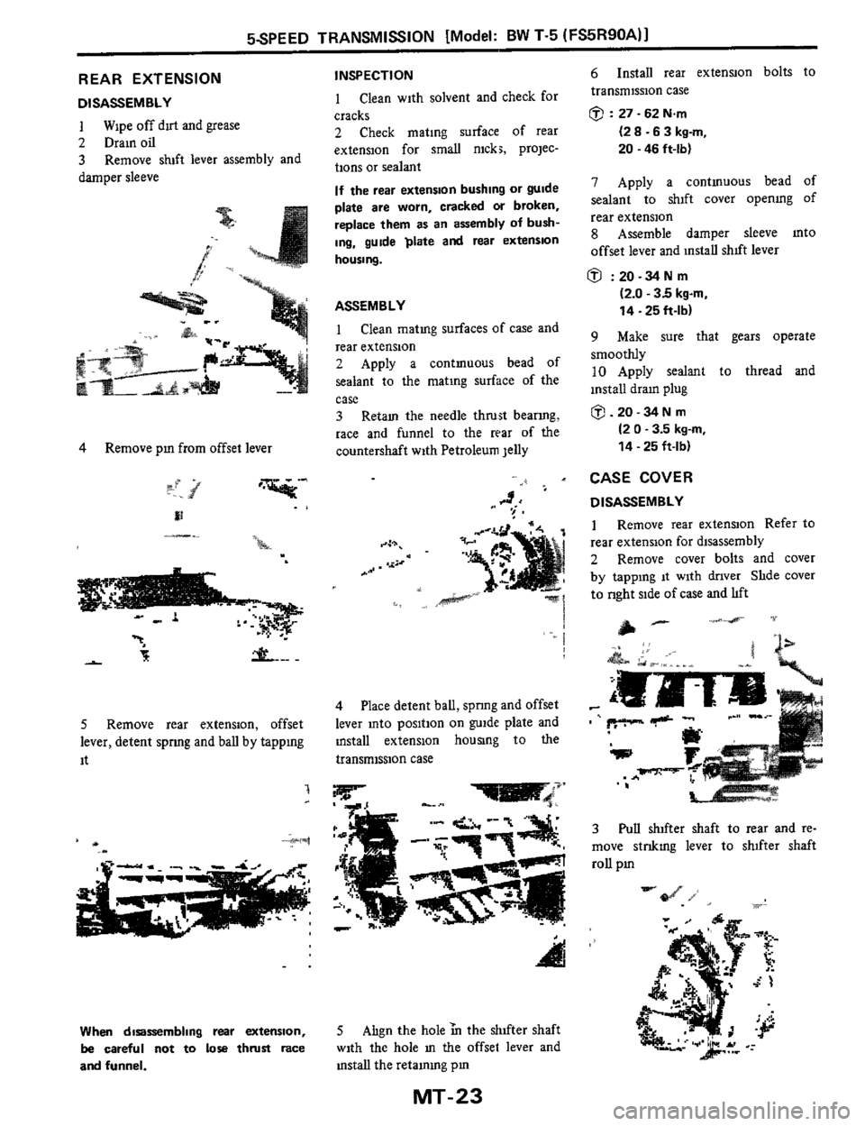
REAR EXTENSION
DISASSEMBLY
1
2 Drain oil
3
damper sleeve
Wipe off drt and grease
Remove sluft lever assembly and
4 Remove pm from offset lever
-.. - ._
'.* .I El
-.. n
5 Remove rear extension, offset
lever, detent
spnng and ball by tappmg
it
7
When disassembling rear extension,
be careful not to lose thrust race
and funnel.
INSPECTION
1 Clean with solvent and check for
cracks
2 Check mating surface of rear
extension for small nicks, prolec-
tions or sealant
If the rear extension bushing or guide
plate are worn, cracked or broken,
replace them as an assembly of bush-
ing, guide plate and rear extension
housing.
ASSEMBLY
1 Clean matmg surfaces of case and
rear extension
2 Apply a contmuous bead of
sealant to the matmg surface of the
case
3 Retam the needle thrust bearmg,
race and funnel
to the rear of the
countershaft with Petroleum Jelly
4 Place detent ball, spnng and offset
lever mto position on guide plate and
install extension houslng to the
transmission case
5 Ahgn the hole ?n the shifter shaft
with the hole
m the offset lever and
mstall the retammg pm
MT-23
6 Install rear extenQon bolts to
transmission case
0 : 27 - 62 Nm
(2 8 -6 3 kg-m,
20 - 46 ft-lb)
7 Apply a contmuous bead of
sealant to shlft cover opening of
rear extension
8 Assemble damper sleeve mto
offset lever and install shlft lever
@ :20-34Nm
(2.0 - 3.5 kgm,
14 .25 ft-lb)
9 Make sure that gears operate
smoothly
10 Apply sealant to thread and
install dram plug
0.20 - 34 N m
(2 0 - 3.5 kg-m,
14
- 25 ft-lb)
CASE COVER
DISASSEMBLY
1 Remove rear extension Refer to
rear extension for disassembly
2 Remove cover bolts and cover
by tapping it with dnver Shde cover
to nght side of case and hft
3 Pull shifter shaft to rear and re-
move stnkmg lever to shlfter shaft
roll pm