Page 17 of 24
ADJUSTABLE SHOCK ABSORBER
Harness Description
Sub-harness
Rear shock absorber
SFA590
Electrical Circuit
SCHEMATIC
I I l,* I"" I
SOFT NORMAL 0 V
SOFT 7 5 V FIRM NORMAL 0 V
I 111-4 IOV I
SFAS82
FA-I 7
Page 18 of 24
Page 19 of 24

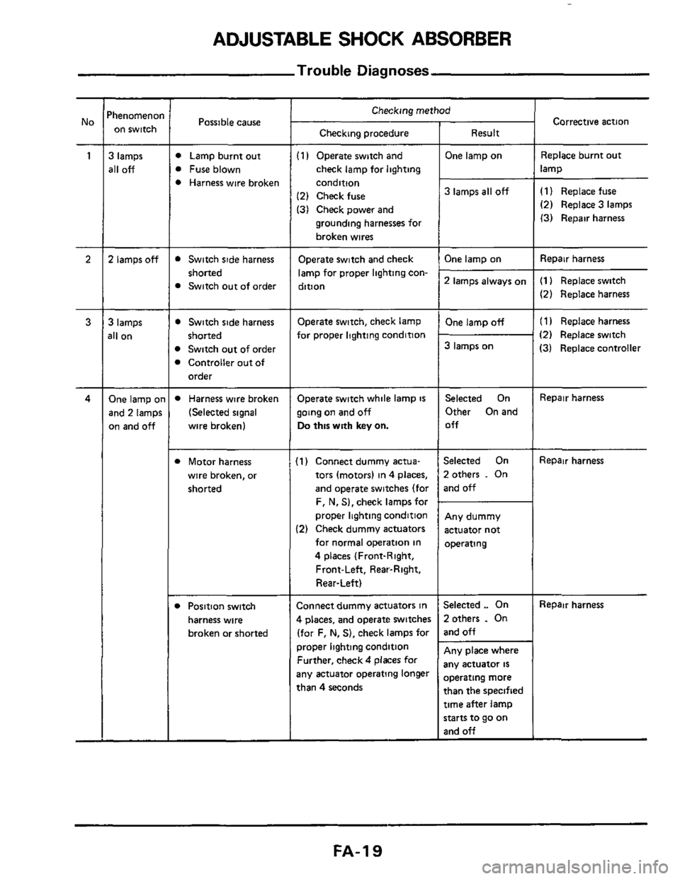
ADJUSTABLE SHOCK ABSORBER
Trouble Diagnoses
Possible cause
D Lamp burnt out
B Fuse blown
B Harness wire broken
Checking procedure
(1 I Operate switch and
check lamp for lighting
condition
(2) Check fuse
(31 Check power and
grounding harnesses for
broken wires ~~~~~~
Switch
side harness
shorted
Switch out of order
D Switch side harness
B Switch out of order
B Controller out of
shorted
order
Operate switch and check
lamp for proper lighting con-
dition
Operate switch, check lamp
for proper lighting condition
D Harness wire broken
(Selected signal
wire broken)
Operate switch while lamp is
going on and off
Do this with key on.
Corrective action
I Checking method 'henomenoi
on switch
3 lamps
all off
2 lamps off
Result
One lamp on
Replace burnt out
lamp
3 lamps all off (1) Replace fuse
(2) Replace 3 lamps
(3) Repair harness ~~
Repair
harness One lamp on
2 lamps always on (1) Replace switch
(2) Replace harness
(1 I Replace harness
(2) Replace switch
(31 Replace controller
3 lamps
311 on
One lamp off
3 lamps on
One lamp 01
and 2 lamps
on and
off
Selected On
Other On and
Off Repair harness
B Motor harness
wire broken, or
shorted
(1) Connect dummy actua-
tors (motors) in 4 places,
and operate switches (for
F, N, S),check lampsfor
proper lighting condition
(2) Check dummy actuators
for normal operation in
4 places (Front-Right,
Front-Left, Rear-Right,
Rear-Left)
Selected On
2otherr
. On
and off
Repair harness
Any dummy
actuator not
operating ~ ~~
Connect
dummy actuators in
4 places, and operate switches
(for F,
N. S), check lamps for
proper lighting condition
Further, check
4 places for
any actuator operating longer
than
4 seconds
Selected ._ On
2 others . On
and off
Repair harness D Position switch
harness wire
broken or shorted
Any place where
any actuator
is
Dperating more
than the specified
time after lamp
starts to go on
and off
FA-I 9
Page 20 of 24

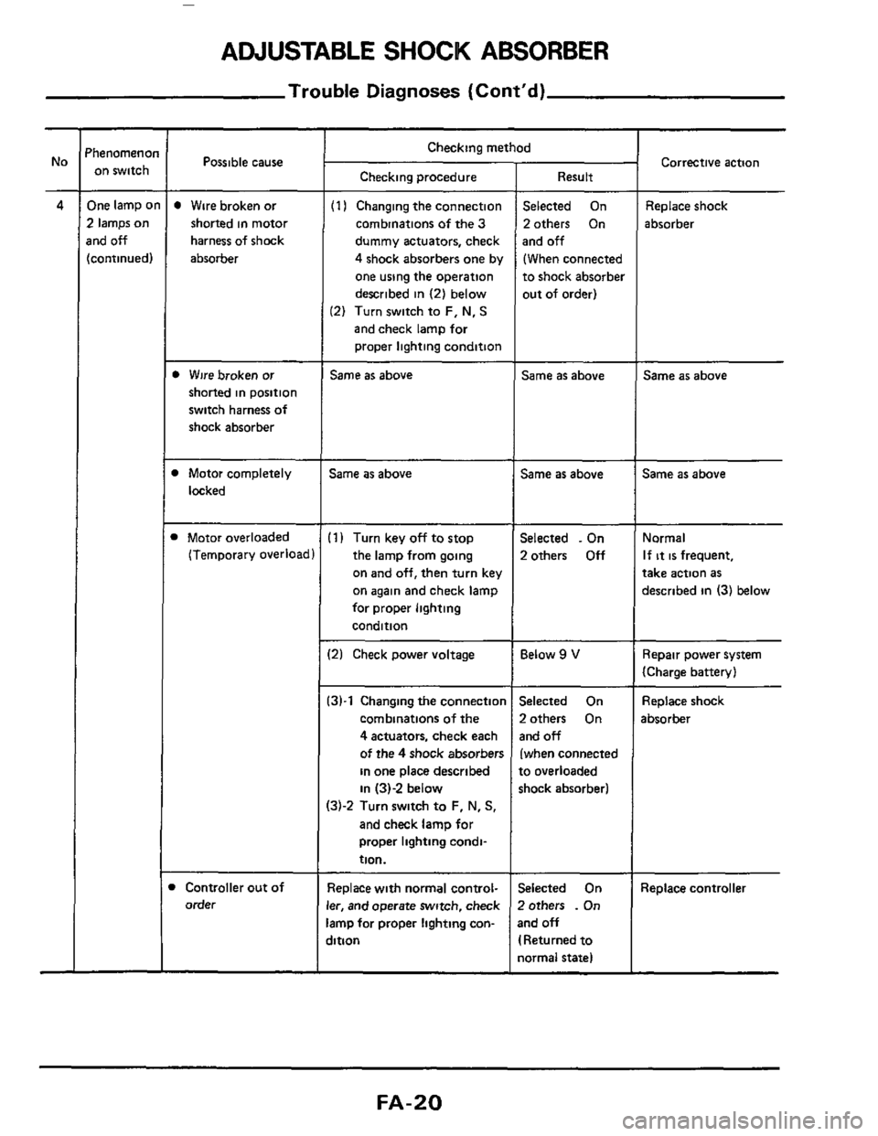
ADJUSTABLE SHOCK ABSORBER
Trouble Diagnoses (Cont'd)
'henomenoi on switch
One lamp o
2 lamps on
rnd off
[continued)
Possible cause ~
Wire
broken or
shorted in motor
harness of shock
absorber
b Wire broken or
shorted in position
switch harness of
shock absorber
1 Motor completely
locked
1 Motor overloaded
(Temporary overload
Controller out of
order
Checking method
Checking procedure
(1 I Changing the connection
combinations
of the 3
dummy actuators, check
4 shock absorbers one by
one using the operation
described
in (2) below
(2) Turn switch to F, N, S
and check lamp for
proper lighting condition
Same as above
Same as above
(1) Turn key off to stop
the lamp from going
on
and off, then turn key
on again and check lamp
for proper lighting
condition
12) Check power voltage
:3)-1 Changing the connectior
combinations of the
4 actuators, check each
of the
4 shock absorbers
in one place described
in 131-2 below
13j-2 Turn switch to F, N, S,
and check lamp for
proper lighting condi-
tion.
Replace with normal control-
er, and operate switch, check
amp for proper lighting con-
jition
Result
Selected On
2others On
and
off
(When connected
to shock absorber
out of order)
Same as above
Same as above
Selected . On
2others
Off
Below 9 V
Selected On
2others On
and off
(when connected
to overloaded
shock absorber1
jelected On
Zothers
. On
3nd off
I Returned to
iormal state)
Corrective action
Replace shock
absorber
Same as above
Same as above
Normal
If it is frequent,
take action as
described in (3) below
Repair power system
(Charge battery)
Replace shock
absorber
Replace controller
FA-20
Page 21 of 24
ADJUSTABLE SHOCK ABSORBER
Trouble Diagnoses (Cont'd)
'henomenon on switch
3 lamps on
and
off
Possible cause
Switch malfunction
Switch contact
out of order
Harness disconnected
Cherking method
Checking procedure
Turn key off to stop the lamp
from going on and off, then
turn key on again and check
lamp for proper lighting con-
dition
(1) Operate switch, check
lamp for proper lighting
condition
(2) Turn switch to original
position, and check lamp
for occurrence of on and
off condition
Turn key off to stop the lamp
from going on and off,
then turn key on again and
check lamp for propc-
lighting condition
Result
Selected On
2others
. Off
Selected - On
2 others .. Off
3lamps .On
and off
3 lamps On
and off
Corrective action
Replace switch
ReDlace switch
ReDair harness
FA-21
Page 22 of 24

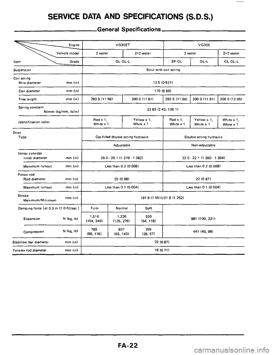
SERVICE DATA AND SPECIFICATIONS (S. D.S.)
General Specifications
VG30ET
Vehicle model 2 seater 2+2 seater
GL GL-L
VG30E
2 seater 2+2 seater
SF GL GL-L GL GL-L
13 5 (05311 ~ ~~
~~
Coil diameter mm (in1 170 (6 691
Free length mm (~nl
strut
TYDe I Gasfilled double acting hydraulic
293 5 (11 56) 3000lll811 293 5 (1 1 561 300 0 (1 1 81 1 306 0 (12 051
Double acting hydraultc
Red x 1, White x 1 ldentlflcat8an color
I Adptable I Non-adlustable
Yellow x 1, fled x 1. Yellow x 1, Whm x 1, White x 1 White x 1 White x 1 White x 1
lnnter cvlmder Inner diameter
Stroke mm Iinl
Damping force [at 0 3 m (1 0 ft)/rec 1
Maxtmum/Minimum ~~
~
mm Iin) 350-35 1 (1 378- 13821
191 8 17 5511131 8 I1 2521
Ftrm Normal Soft ~~ ~
~
32 0 - 32 1 (1 260 - 1 2641
(kg'lb' Expansion
Less than 0 2 (0 008) Less than 0 2 (00081 I Maximum runout mm (in1 1
981 1100, 221) 1.510 1,226 530
(154,3401 (125,2761 (54. 1191
Piston rod
Rod diameter
785
(80. 1761 N Ikg, Ib) Compression
mm (ml 25 (0 981 I 22 10 87)
441 (45.991 637 255
(65. 1431 (26. 571
Maxmum runout mm (in1 I Less than 0 1 10 0041 I Less than 0 1 10 0041
Stabilizer bar diameter mm (In) I 22 (0 871
Tension rod diametei mm (in) I 181071)
FA-22
Page 23 of 24

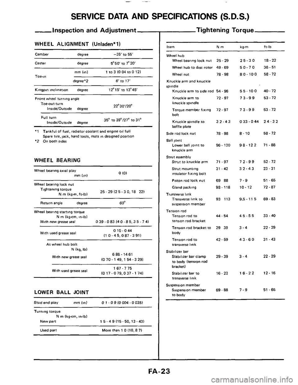
SERVICE DATA AND SPECIFICATIONS (S.D.S.)
-Inspection and Adjustment
WHEEL ALIGNMENT (Unladen'l)
Camber degree -35' to 55'
Carter degree 5'50 to 7'20
mm lml 1103 1004100 121 TOe-ltl degree'2 6 to 17'
Kingpin inclinatmn degree 12'15'10 13'45'
Front wheel turning angle
22'30'120" Toe-aut-turn
Inside/Outslde degree
35' to 39"/27' to 31' Full turn InridelOutslde degree
'1
'2 On both sides
Tankful of fuel, radiator coolant and engine 011 full
Spare
tire. jack, hand t001s. mats in desngned position
WHEEL BEARING
0 I01 Wheel bearing axial play
mm (in1
Wheel bearing lock nut
25 - 29 12 5.3 0,18 221 Tightening torque
N m Ikg-m.ft-lbl
Return angle degree 60'
Wheel bearing stanmg torque
N m (kgcm. in-lbl
With new grease seal 0 39.0 83 14 0 -8 5,3 5.7 41
010-044 I1 0 -45,087 - 3 911 Wlth used grease seal
At wheel hub bolt
N (kg, Ib)
686- 1461
10 70.149,l 54 -3 291 Wtth new grease seal
1 67 - 7 75
10 17.0 79,037.1 741 With wed grease seal
LOWER BALL JOINT
Stud end play mm 1ml 0 1 - 0 9 10004 -0 0351
Turnlng torque
New pan
N m Ikgcm. m-lb)
1 5 - 4 9 (15- 50,13 -431
Used part Morethan 1 OllO.87l
- Tightening Torque
-
Ire," Nm kg-m ft-lb
Wheel hub
Wheel bearing lock nut 25 - 29
Wheel hub to dtw rotor 49 - 69
Wheel nut 78 - 98
Knucklearm and knuckle
spindle
Knuckle arm to ride rod 54.98
Knuckle arm to 72 - 97
knuckle spindle
Toique member fixing
bolt
Knuckle spindle to
baffle plate
Side rod lock
nut
Ball joint
72 - 97
3 2.4 3
78 - 98
Lower ball pint to
knuckle arm
Strut to knuckle arm 71 - 97
Strut mounting 31 -42
insulator fixing bolt
Piston rod
lock nut 69 88
96. 120
Strut assembly
Gland packing 98-118
Tr.mrverre link Transverse link to 93 113
wspeniion member
Tension rod Tension rod to
tenmn rod bracket
Tenson rad bracket
to 29 39
body
Tension rod
to
transverse link
Stabilizer bar clamp 29. 39
to body (tension rod bracket)
Stablllzer bar to 16-22
transverse link
Surpenrlon member
Suspension member
69 - 88
to body
44 - 54
42 - 59
Stabilizer bar
25-30
50-70
80-100
55-100
73-99
73-99
0 33.044
8-10
98-122
72-99
32-43
7-9
10-12
9.5-11 5
45-55
3-4
43-60
3-4
16-22
7-9
18-22
36
- 51
58
- 72
40.72 53
- 72
53 - 72
24-32
58.72
71 -88
52.72
23-31
51 -65
72.87
69.83
33 - 40
22.29
31 -43
22 - 29
12-16
51 -65
Page 24 of 24
SPECIAL SERVICE TOOLS
ST35490000 (526083)
Tool name Tool number
(Kent-Moore
No )
Gland packing wrench
ST35652000 Clamp
(-)
HT72520000 Ball joint remover
(525730-A)
FA-24
Page:
< prev 1-8 9-16 17-24