Page 84 of 116
TIME CONTROL SYSTEM
Trouble-shooting (Cont'd)
Intermittent time of wiper cannot be adjusted
Check intermittent wiper volume circuit
Check harness between T C U
and intermittent wiper volume
Replace
wiper switch
~~~_____ ~~ ~
1
2 Measure resistance between @J and @
Turn ignition switch to "OFF"
while turning intermittent wiper volume.
Check from harness side
Ignition switch OFF
0-1 kS2
Intermittent wiper knob
0 Rat S posmon
1 kR at L postiton Approx
Ohmmeter SEL710D
combination
Check washer switch circuit
I NG f
Replace T C U Check harness between
T C U and washer switch
1
2
3
Turn ignition switch to "OFF".
Turn washer switch to "ON"
Check continuity between @ and @
Check from harness side
lgnitjon rwrtch OFF
WASH
I
Ohmmeter SEL711D
EL-84
Page 99 of 116

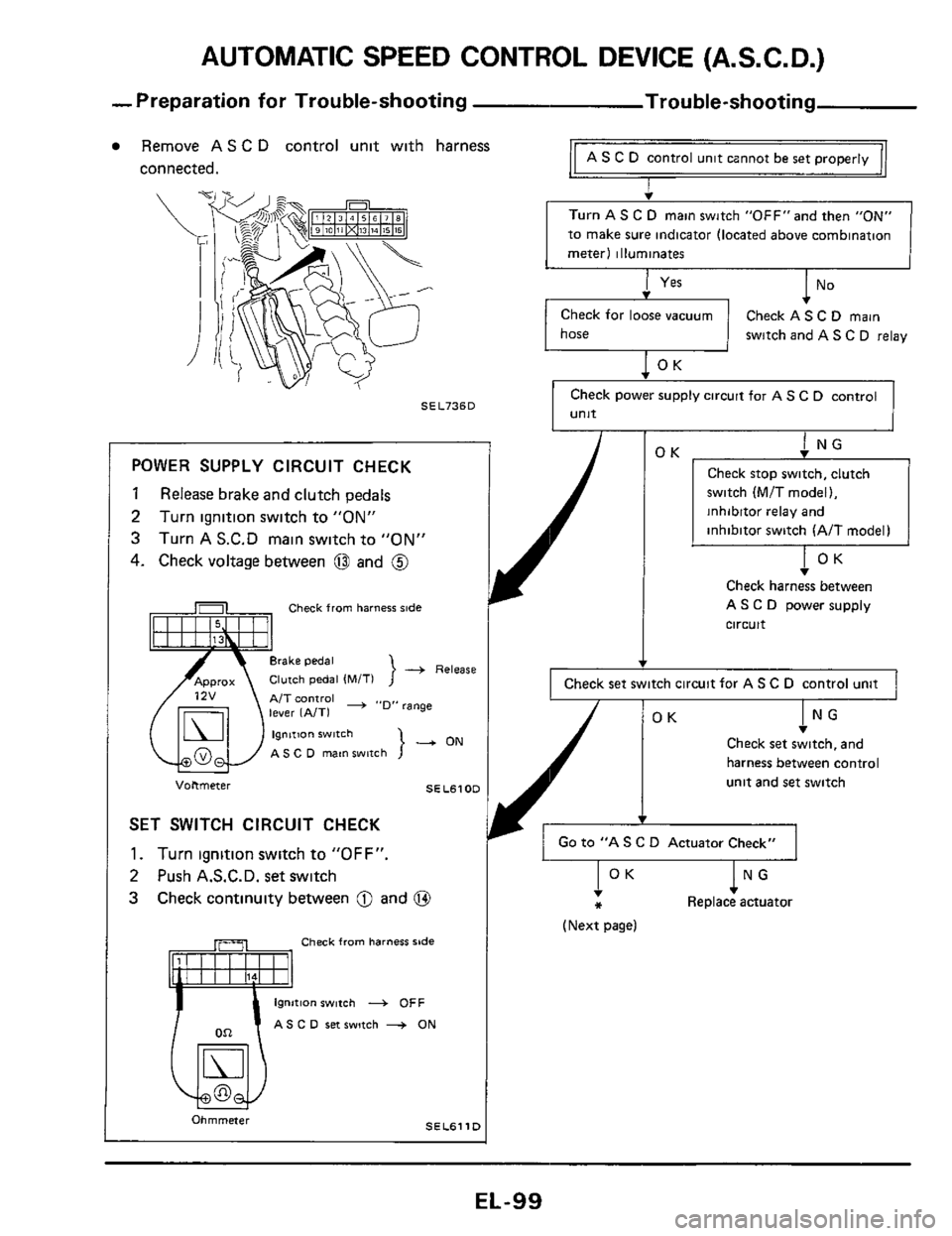
AUTOMATIC SPEED CONTROL DEVICE (A.S.C.D.)
-Preparation for Trouble-shooting Trouble-shooting
Remove AS C D control unit with harness AS C D control unit cznnot be set properly connected. I
Turn AS C D main switch "0FF"and then "ON"
to make sure indicator (located above combination
meter1 illuminates
Check for loose vacuum Check AS C D main
[-I switch and AS C D relay
Check power supply circuit for
A S C D control
unit SEL736D
Check stop switch. clutch
switch (MIT model).
inhibitor relay and
inhibitor switch (AIT model) POWER SUPPLY CIRCUIT CHECK
1 Release brake and clutch pedals
2 Turn ignition switch to "ON"
3 Turn A S.C.D main switch to "ON"
4. Check voltage between 0 and @ v Check harness between
AS C D power supply Check from harness side
-+ Release
A/T control -+ ..D" range
AS C D main wnch }-ON IOK Checksets:and
harness between control
unit and
set switch Voltmeter SELSlOD
SET SWITCH CIRCUIT CHECK
1. Turn ignition switch to "OFF". Go to "A S C D Actuator Check" -
2 Push A.S.C.D. set switch
3 Check continuity between 0 and @
Check from harness side
tion switch 4 OFF
C 0 ret switch + ON
SELBllD Ohmmeter
I
circuit
I Check set switch circuit for AS C D control unit 1
lNG Replace actuator !OK *
(Next page)
EL-99
Page 100 of 116
AUTOMATIC SPEED CONTROL DEVICE (A.S.C. D.)
Trouble-shooting (Cont'd)
Turn ignition switch to "OFF"
Disconnect speedometer cable from trans-
mission
Connect an ohmmeter between
@ and
Slowly turn speedometer cable pinion by
hand to make
sure ohmmeter pointer
deflects
Ohmmeter pointer deflects twice per
rotation
of pinion.
0.
Check from harness side
Ohmmeter SEL7630
i
Check speed sensor circuit
(Digital type combination meter) -
(Refer to "METER AND GAUGES
- Needle Type Combination Meter"
~~~l~~~ AS c D
control unit
Check harness between A S C D
control unit and speed sensor
signal output terminal
of
combination meter
Does speedometer operate properly?
Go to "Speed Sensor Signal Check"
for checking combination meter
(Refer to "METER AND GAUGES
- Digital Type Combination Meter" )
Replace
speed sensor Check harness between AS C D
control unit and speed sensor
signal output terminal of
combination meter
EL-I 00
Page 105 of 116
LOCATION OF ELECTRICAL UNITS
hock absorber
Direction sensor
Lock-up mntrol unit (For electronic controlled automatic tranmisionl
(Only for Canada digital L------ type combination meter I ~UIDU~ madell
Fuel pump relay r,
(Rear side inner
SEL75ZD
EL- 1 05
Page 106 of 116
LOCATION OF ELECTRICAL UNITS
LWarning chime Meter power unit (For digital
type combination
meter1
Hold relay (only for Canada
analog type
Clutch witch (For AS C D I
(For A 5 C D )
box
SEL753D
EL-I 06
Page 113 of 116
@ To @ (Non-turbocharger models) 0 Ambient temp sensor 0 Vacuum tank (Turbocharger models)
0 To @I (Turbocharger models) 0 PoglampRH @ Hoodswitch
0 To @il White) @ Vacuumpump 0 I'oglampLH @ Hoadlamp washer motor
0 @D Horn L H
/ @ Side marker lamp L H
0 To @I (Blue) (Turbocharger models)
@ To @ White) 0 ranmotor
@ Uphold relay (Turbocharger models)
@ Fuublchk @ Headlamp motor R H
0 Front shock absorber R H @ Radiator coolant level switch 0 Hcadlamp L H
Front combmation lamp L H
A/T relay I @ AS C D relay (Non-turbocharger AIT models) @ Water cock an valve Compressor relay 0 Headlamp R H Vacuum pump relay @ Side marker lamp R H
(Turbocharger models) @ Horn RH Horn relay @ Front combination lamp R H
6 Headlamp tmer @ To @ (Blue) I@ To @ (White)
@Q To @ (White) @ To 0 (Non-turbocharger models)
@ Inhibitor switch (Non-turbocharger models)
Page 114 of 116
0 To @I (White) 0 Diode (Voice warnmg system equipped
0 To @ (Blue) (GLL models) models except CLL models) 0 To @ Wile) 0 Speakcr R H (CLL models) 0 Jomt (POI 0, sensor warning lamp) 0 Glove box lamp switch @O Glove box lamp @ Hold relay (Canada models)
0 @9 To (Black) @9 . To 0 (White)
To @ (Blue) (GLL models)
Speak; L H (GLL models)
IUumlnation control switch
Instrument swtch
L H
Instrument swtch L H
Combination meter (Black)
Combination meter (While)
Combination meter (White)
Combination meter White)
Combination meter (White)
Combination meter (Blue)
Combmation meter (Black)
Chune Instiument switch
R H
Instrument switch R H
Needle type meter
Digital type meter
& Combmation gauge (CLL models)
@ Combmalion gauge (SF and CL models)
TO COMBINATION
METER (BRAKE WARNING LAMPI
TO ENGINE ROOM H (BRAKE FLUID LEVEL SWI
6 TO MAIN H IPARKING
BRAKE SW AND VOICE
WARNING UNIT1
[For voice warnmg system1