Page 17 of 116
CHARGING SYSTEM -Alternator-
Construction
A2T48195 (MITSUBISHI make) 
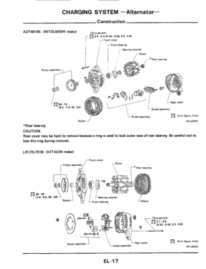
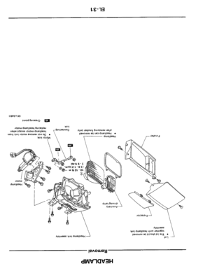
Through-bolt m39 541040-055.29 401
,- Front cover r I
- ~ear~ng retainer
- Diode assembly 16 0.7 5,43 54)
("1 N m lkg-rn. it-lbl
SEL625D
*Rear bearing
CAUTION. Rear cover may be hard to remove because
a ring is used to lock outer race of rear bearing Be careful not to
lose this ring during removal.
LR170-701B (HITACHI make)
(4 0 -6.0, 29.43) n 39 59
("1 N m Ikg-m, ft-lbl
Dlodt, assembly SEL626D
EL-I 7
Page 18 of 116
____ ____
CHARGING SYSTEM -Alternator-
Removal
Remove bolts from alternator
Remove bolts for front stabilizer
Manually
move stabilizer down and remove
alternator
SEL627D
Disassembly
CAUTION.
Rear cover may be hard to remove because a ring
IS used to lock outer race of rear bearing To facili-
tate removal of rear cover, heat just bearing box
section with
a 200-wan soldering iron
Do not use a heat gun, as it can damage diode
assembly.
SEL628D
Rotor Slip Ring Check
1. Continuity test
Ohmmeter
SEL629D
No continuity Replace rotor
2. Insulator test
Ohmmeter
IWI
SEL630D
Continuity exists. Replace rotor.
3. Check slip ring for wear.
Slip ring minimum outer diameter.
21.6 mm (0.850 in) [HITACHI makel
22.4
mm (0.882 in) [MITSUBISHI makel
EL-I 8
Page 19 of 116
CHARGING SYSTEM -Alternator-
Brush Check
1 Check smooth movement of brush
Not smooth Check brush holder and
clean
2 Check brush for wear
SEL631D
Replace brush if it is worn down to the
3. Check brush pig tail for damage
Damaged Replace
4 Check brush spring pressure
Measure brush spring pressure with brush pro-
jected approximately
2 mm (008 in) from
brush holder
Spring pressure.
limit line
1.471 - 3.531 N (150 - 360 9,
5.29 - 12.70 02) [HITACHI make]
10.93 - 15 17 02) [MITSUBISHI make]
3.040 - 4 217 N (310 - 430 9,
2 mm (0 08 in1
IP-
EE049
Not in the specified value Replace
- Stator Check
To test the stator or diode, you must separate
them
by unsoldering the connecting wires.
CAUTION.
Used only
as much heat as required to melt solder.
Diodes will
be damaged by excessive heat.
Long nose pliers used a$ a heal sink
-1, /
SEL054D
1 Continuity test
y_ Lead wire -
SEL070
No continuity Replace stator
2 Ground test
SE LO7 1
Continuity exists Replace stator
EL-19
Page 20 of 116
CHARGING SYSTEM -Alternator-
Ohmmeter probes
~ositive 0 Negative 8
Positive diode plate Diode terminals
Diode terminals Positive diode plate
Negative diode plate Diode terminals
Diode terminals Negative diode plate
Diodes check (Positive side)
Diodes check (Negative side)
Diode Check
Continuity
Yes
No
No
Yes
[ MlTSUBlSHl makel
Negatwe diode plate
piate
SEL767D Sub dlode
Subdiode
Attach ohmmeter's probe to each end of diode
to check for continuity.
SEL910A
Continuity is N.G. ... Replace diode assembly.
[HITACHI makel
SEL768D
Subdiode
Attach ohmmeter's probe to each end of diode
to check for continulty.
Continuity is N.G. . Replace diode assembly
EL-20
Page 21 of 116
CHARGING SYSTEM -Alternator-
Reasi
Carefully observe the following instructions
1 When soldering each stator coil lead wire to
diode assembly terminal, carry out the opera-
tion
as fast as possible
2 When soldering brush lead wire, observe the
following
Position brush so that its wear limit line
protrudes 2 mm (0 08 in) beyond end face
of brush holder
Solder points
SEL6320
3 Fit ring into groove in rear bearing so that it is
as close to the adjacent area as possible.
Quantity of prorrusion FIX ring at the position of minimum protrusion
mbly
4 Before installing front cover with pulley and
rotor with
rear cover, push brush up with
fingers and retain brush, by inserting brush
lift
into brush lift hole from outside
After installing, remove wire for brush
lift
EE540
EE541
5 After installing front and rear sides of alter-
nator, pull brush lift by pushing toward center
Do not pull brush lift by pushing toward outside
of cover as it will damage slip ring sliding surface.
EL-21
Page 22 of 116
CHARGING SYSTEM -Alternator-
Service Data and Specification
LR170-701B
Applied model
A2T48195
Nominal rating V-A
Ground wlarity
Minimum revolution undt no-load (when 14 volts IS
applied) rpm
Hot output current
Alrpm
Regulated output voltage
V
Minimum length of brush rnm (m)
Brush spring pressure
N 1% 02)
Slip ring outer diameter
mm Ion)
W8thout turbo With turbocharger
charaer models models
12-70
Negative
Less than 1.000
More than
2111,300
More than
5012,500
More than
7015,000
144-150
More than
55102171
1,471 - 3,531
1150-360.
5 29
- 12 701
More than
21
6 IO 850)
Less than 1,100
More than
21 11,300
More than
5012,500
141 147
More than
8 10311
3,040 4,217
I310
- 430,
1093- 15 17)
More than
22 4
10 8821
Page 23 of 116
COMBINATION SWITCH
Intermittem WIPER
wimrvolume
WASH
TURN
Horn terminal RESUME
OFF
INT s
L
4
LO
HI
ASCD
LIGHTING SWITCH WIPER SWITCH INTERMITTENT
WIPER VOLUME AS C D SWITCH
HORN SWITCH
TURN
SIGNAL
SWITCH
-
SEL64ZD
EL-23
Page 24 of 116
COMBINATION SWITCH
Replacement
Lighting switch, wiper & washer switch and
AS C D switch can be replaced without removing
combination switch base
Swtch base
Lighting switch
Washer swmh
A S C D sei switch SEL643D
To remove combination switch base, remove base
attaching screw and turn after pushing on
it
Attaching screw
Protrusion gu!dei
Hole
SEL644D
EL-24