Page 1 of 116

ELECTRICAL SYSTEM
I
SECTION EL
CONTENTS
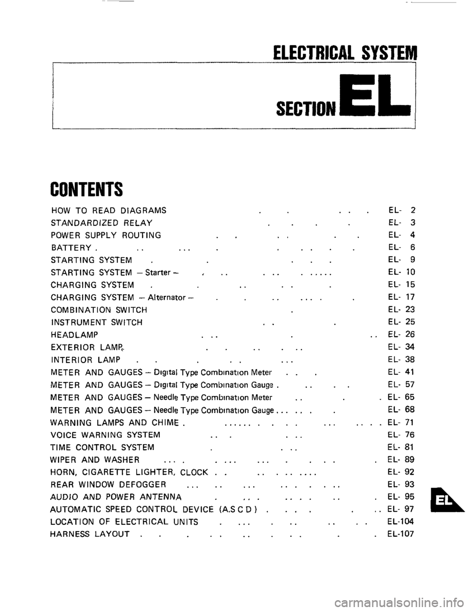
HOW TO READ DIAGRAMS
STANDARDIZED RELAY
POWER SUPPLY ROUTING
BATTERY.
.. ..
STARTING SYSTEM .
STARTING SYSTEM -Starter -
CHARGING SYSTEM .
CHARGING SYSTEM - Alternator
COMB IN AT1 ON SWITCH
INSTRUMENT SWITCH
HEADLAMP
EXTERIOR LAMP,
INTERIOR LAMP
.
..
..
..
..
..
... ......
..
.. ....
..
.. ...
EL- 2
EL- 3
EL- 4
EL- 6
EL- 9
EL-
10
EL- 15
EL- 17
EL- 23
EL- 25
EL- 26
EL- 34
EL- 38
METER AND GAUGES - Digital Type Combination Meter . . EL- 41
METER AND GAUGES - Digital Type Combination Gauge . .. .. EL- 57
METER AND GAUGES - Needle Type Combination Meter .. . EL- 65
METER AND GAUGES
- Needle Type Combination Gauge.. .... EL- 68
WARNING LAMPS AND CHIME. .......... ... .... EL- 71
VOICE WARNING SYSTEM
... ... EL- 76
TIME CONTROL SYSTEM ... EL- 81
WIPER AND WASHER .... .... ... ... . EL- 89
HORN, CIGARETTE LIGHTER, CLOCK . . ......... EL- 92
REAR WINDOW DEFOGGER
... .. ... ....... EL- 93
AUDIO AND POWER ANTENNA
,. . .... .. . EL- 95
AUTOMATIC SPEED CONTROL DEVICE (AS
C D ) . ... , . EL- 97
LOCATION OF ELECTRICAL UNITS
... .. .. .. EL-104
HARNESS LAYOUT
. . .. .. .. . EL-107
Page 25 of 116
INSTRUMENT SWITCH
p7J-q
INSTRUMENT
RETRACT
SWITCH
HAZARD
SWITCH
E:EGGER SWITCH
OFF
[WJ]
-'+ Dark N (For ASC D switch)
(Far illuminafion
control swifchl
HAZARD RETRACT SWITCH SWITCH
ASCD MAIN
SWITCH
I LLUMlNATlON
CONTROL SWITCH
BRIGHT DARK
El
INSTRUMENT SWITCH R.H.
m
REAR WIPER
&WASHER
SWITCH
RE4R
DEFOGGER
SWITCH REAR WIPER
&WASHER SWITCH
AUXILIARY DRIVING
LAMP SWITCH
For removal, refer to "INSTRUMENT" in BF section
EL-25
Page 38 of 116
III
I- I-
ILLUMINATION ILLUMINATION lllluminai~on CONTROL controt SWITCH switch1
n ILLUMINATION
COMBINATION
METER
INSTRUMENTSWITCH L H m r 0) ul 4 0
COMBINATION INSTRUMENT COMEINATION COMBINATION METER SWITCH R H GAUGE GAUGE
Page 39 of 116
FUSE BLOCK
I BATTERY I
TIME CONTROL UNIT [Refer to "TIME
CONTROL
SYSTEM
I I
LIR
@ SF models
IWhiIel DOOR STEP @ GLmodelr (Door harness R H I LAMP R H @ GLLmodelr
@ D8g1tal tv~e meter
@) Needle type meter
J~/~U
LIR U
I 1 II I
. BODY GROUND IL H ridel
Page 40 of 116
rn I-
0 &
TIME CONTROL UNIT (Refer to 'TIME CONTROLSYSTEM" h
@$
STEP
LAMP R H @=@L/R L/E
INTERIOR
@
:;: STEP LAMP L H
@) Digital type meter
@ Needle type meter
J
Ii DOOR HANDLE
SWITCH
IDoor harness L H )
L/R
G/R KEY HOLE
ILLUMINATION
Page 55 of 116
METER AND GAUGES - Digital Type Combination Meter
Speed Sensor Si!
METER OUTPUT CHECK
Combination meter emits speed sensor signal to
control
E C.C.S. control unit, A.S.C D. control
unit, voice warning
unit and AIT control unit.
Disconnect speedometer cable from speed sen-
sor and remove speed sensor with harness con-
nected 1
2 Remove cluster lid A.
3 Disconnect combination meter harness from
instrument harness
as shown, and connect an
ohmmeter between @ and 0
Ohmmeter
SEL748D
11 Check (Cont'd)
4
5
Turn ignition switch "OFF" + "ON".
Slowly turn speed sensor rotor shaft with a
suitable screwdriver to make sure ohmmeter
pointer deflects.
Ohmmeter pointer deflects twice for each rotatton
of rotor shaft
Ohmmeter -
SEL7490
If ohmmeter pointer does not deflect, go to
"Speed Sensor Output Check". (Refer to back
paw)
EL-55
Page 59 of 116
METER AND GAUGES -Digital Type Combination Gauge
Trouble-shooting
(+)
v
Check power supply circuit for combination
gauge
(-1
l°K 1 NG
Replace combination gauge Check harness
Voltmeter terminal I Ignition switch position
Approx Approx
@ I 03 I OV I 12v ! 12v
Continuity exists @ I gK:d I
Remove radio and A/C control assembly from
center console and remove combination gauge
with harness connected
Check from harness rtde
SEL681D
Display illumination will not darken when light
1 switch is "ON"
I Check light switch circuit for combination gauge I
1 Remove radio and A/C control assembly
and remove combination gauge with har-
ness connected.
Turn ignition switch to
"OFF"
Turn light switch to "ON"
Measure voltage across @ and @
2
3
4
Ignition switch - 0
ht switch - ON
SEL682D L
EL-59
Page 62 of 116
METER AND GAUGES -Digital Type Combination Gauge
Trouble-shooting (Cont'd)
v
IGo to "Direction Sensor Amplifier Output Check" I
1 NG v
Check for loose harness
connector to
amplifier
Check for loose harness
connector to combmatlon
Replace combinatlon gauge Replace amplifier
I
1 Remove radio and AIC control assembly
from center console Remove combi-
nation gauge with harness connected
2. Turn ignition switch to "ON"
3 Check to determine if voltage IS produced
across
0 and @
SELSBSD
ACCELERATION & MILEAGE METERS
deceleration
Does speedometer operate?
1 No
Check harness between
combination gauge and
speed sensor Replace speed sensor
lNG
Replace combination gauge
Mileage meter registers "0" or abnormal value
I
Does speedometer operate?
Replace speed sensor
Check fuel injection pulse circuit for combination
gauge
I NG v
Check harness between
Replace combination
gauge combination gauge and
E F I control unit
IOK
EL-62